


Telemetria de minha motocicleta
Componentes e suprimentos
 |
| × | 1 | |||
| × | 1 | ||||
| × | 1 | ||||
| × | 1 | ||||
 |
| × | 1 | |||
 |
| × | 2 | |||
| × | 1 | ||||
| × | 1 | ||||
 |
| × | 1 | |||
 |
| × | 1 | |||
 |
| × | 1 | |||
 |
| × | 1 | |||
 |
| × | 1 | |||
| × | 1 |
Aplicativos e serviços online
 |
| |||
 |
| |||
| ||||
 |
| |||
| ||||
|
Sobre este projeto
Cada vez que começo um novo projeto, tento criar algo explorando as tecnologias mais recentes relacionadas às minhas paixões. Para este projeto decidi combinar minha paixão pela motocicleta com meu hobby favorito (usar o Arduino).
A ideia
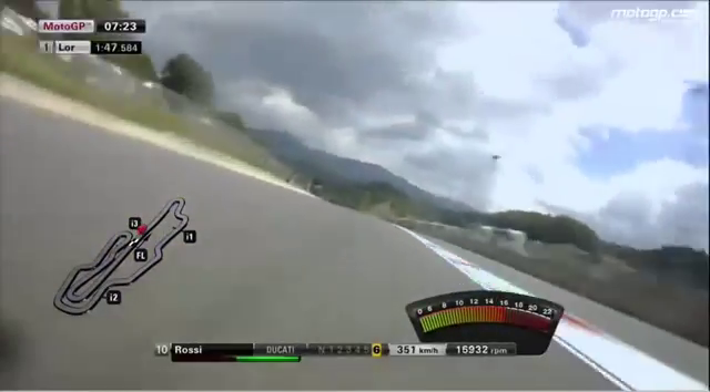
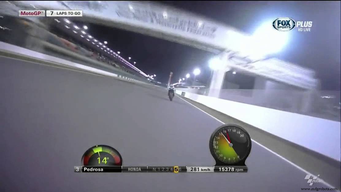
Sempre fui fascinado pelas imagens de telemetria que vejo na TV sobre o motogp. Vendo as imagens abaixo, imaginei como poderia construí-lo usando meu gadget favorito (Arduino) e meu conhecimento de programação.
Decidi então desenvolver um sistema de telemetria baseado em Arduino e Azure, que fosse fácil de replicar para que todos os entusiastas de motocicletas possam ter um em sua motocicleta.
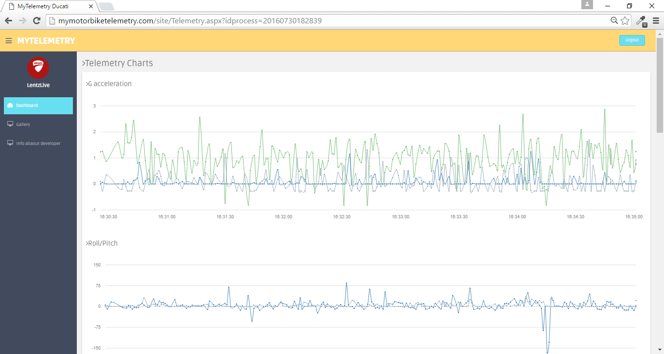
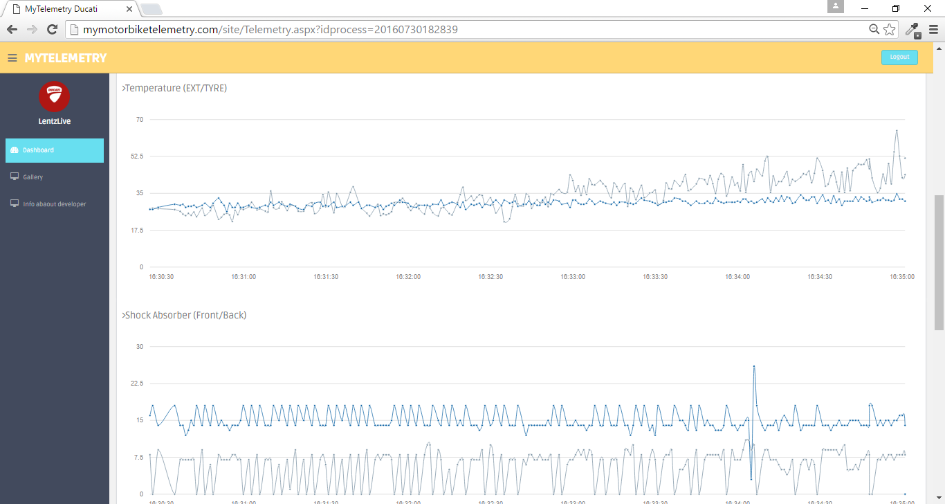
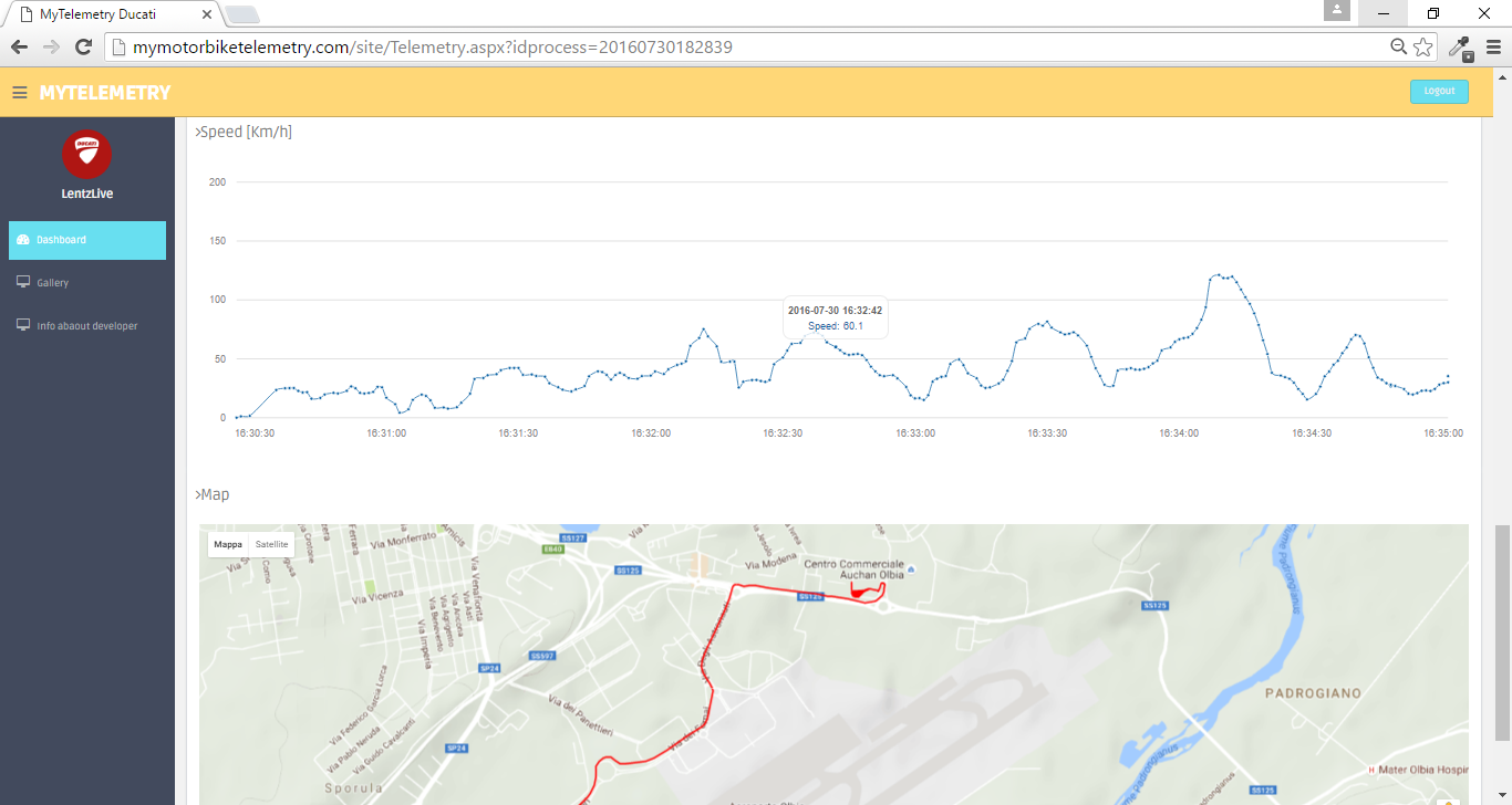
Como será mostrado a seguir, este sistema de telemetria será capaz de obter as seguintes informações sobre o seu estilo de dirigir:
- Velocidade [Km / h]
- Posição GPS (Latitude / Longitude)
- Informações de satélite (número de satélite, Hdop)
- Altituto [metros]
- Ângulo de inclinação
- Ângulo de Wheelie
- Aceleração G nos 3 eixos [m / s ^ 2]
- Temperatura externa [° C]
- Temperatura do pneu traseiro [° C]
- Amortecedor dianteiro [cm]
- Amortecedor traseiro [cm]
Para isso utilizei um Arduino Uno R3, alguns sensores, um UWP implantado em um Windows Phone e alguns serviços Azure.
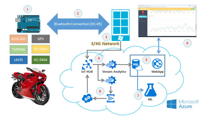
O fluxo de trabalho é descrito na seguinte imagem:
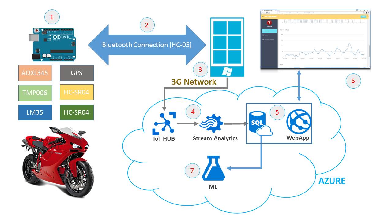
- Fase 1 - Todos os dados de telemetria são adquiridos da unidade de controle cerca de duas vezes por segundo (a unidade de controle é posicionada na motocicleta).
- Fase 2 - Cada vez que os dados são adquiridos, os dados são enviados por bluetooth do Arduino para o Windows Phone .
- Fase 3 - Os dados são exibidos no telefone (para obter mais detalhes, leia a seção "Software") e, em seguida, enviados pela rede 3G / 4G para o Azure IoT HUB .
- Fase 4 - No azure, há um Job do Stream Analytics que recebe os dados do IoT HUB e salva as informações em um banco de dados SQL Azure.
- Fase 5 - No azure foi implantado um WebApp que usam os dados do banco de dados SQL para mostrar os dados de telemetria em tempo real (leia a seção Aplicativo da Web)
- Fase 6 - O WebApp , usa um processo de autenticação e mostra todas as informações de telemetria em gráficos. (Todos os dados são recuperados do banco de dados sql azure usando Entity Framework)
- Fase 7 - Todos os dados salvos no banco de dados SQL azure são processados por um Machine Learning para obter informações sobre o seu "estilo de condução". O escopo compreenderá como modificar seu estilo de direção em função dos parâmetros de telemetria para melhorar seu desempenho ao dirigir.
Acho que ESTÁ BEM LEGAL !!! Vamos começar a descrever o projeto
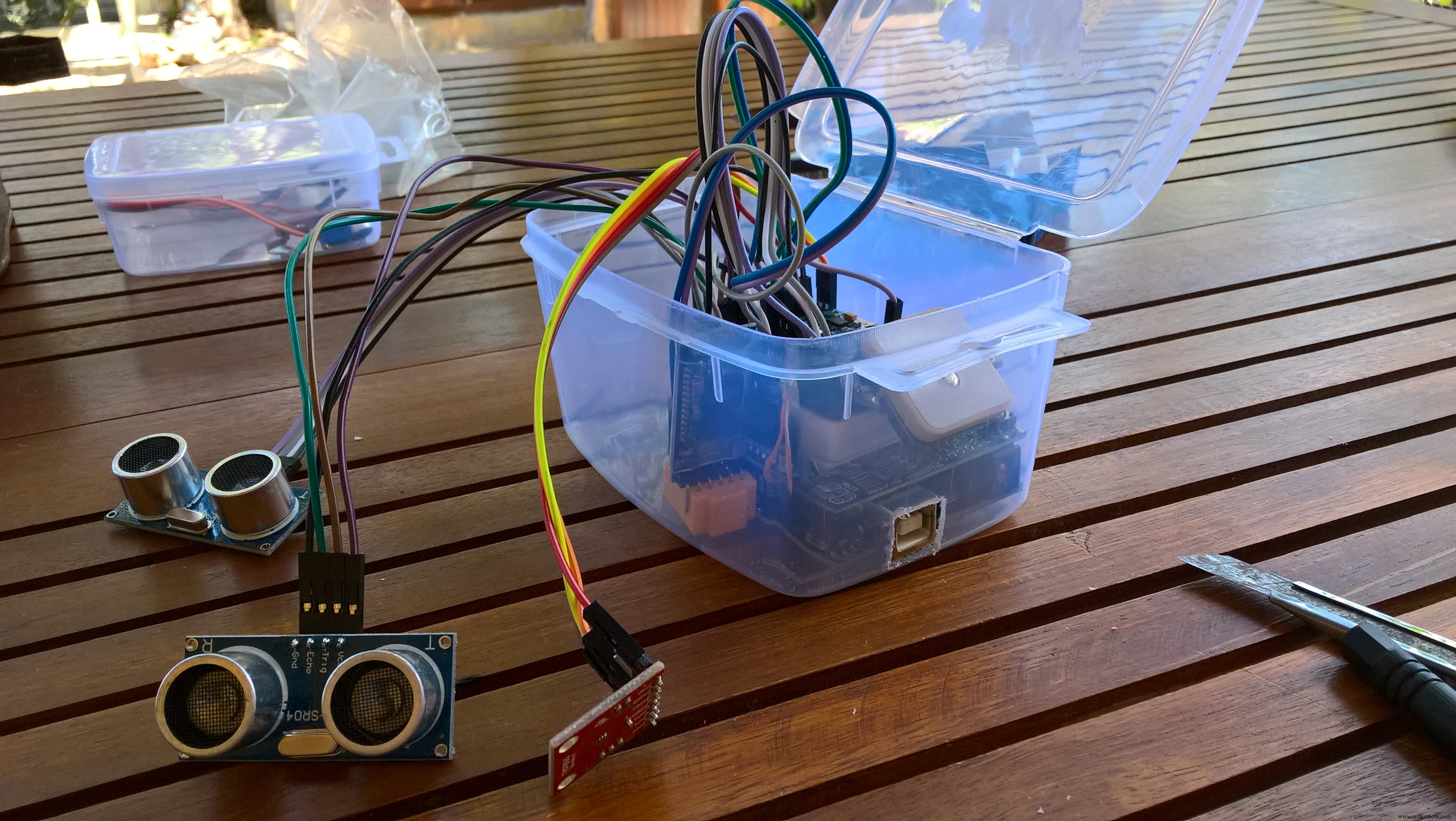
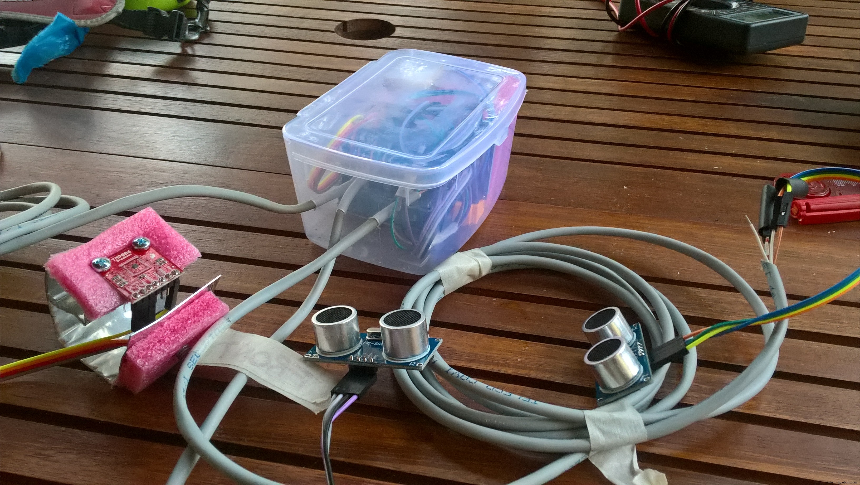
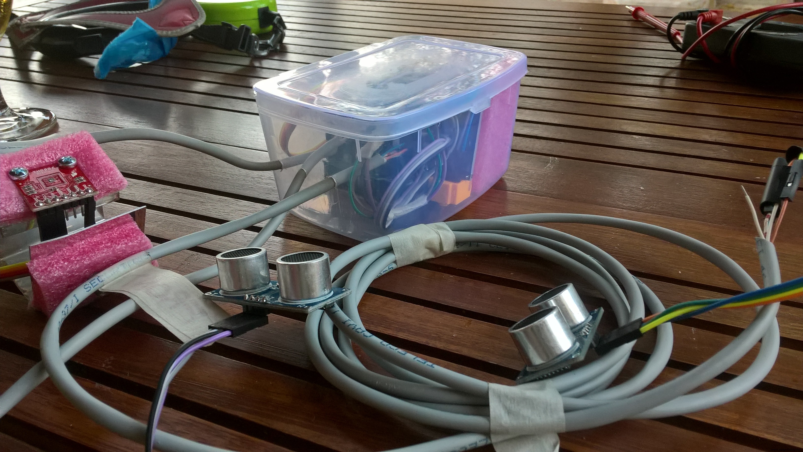
Configuração de hardware
Minha configuração de hardware é mostrada abaixo.
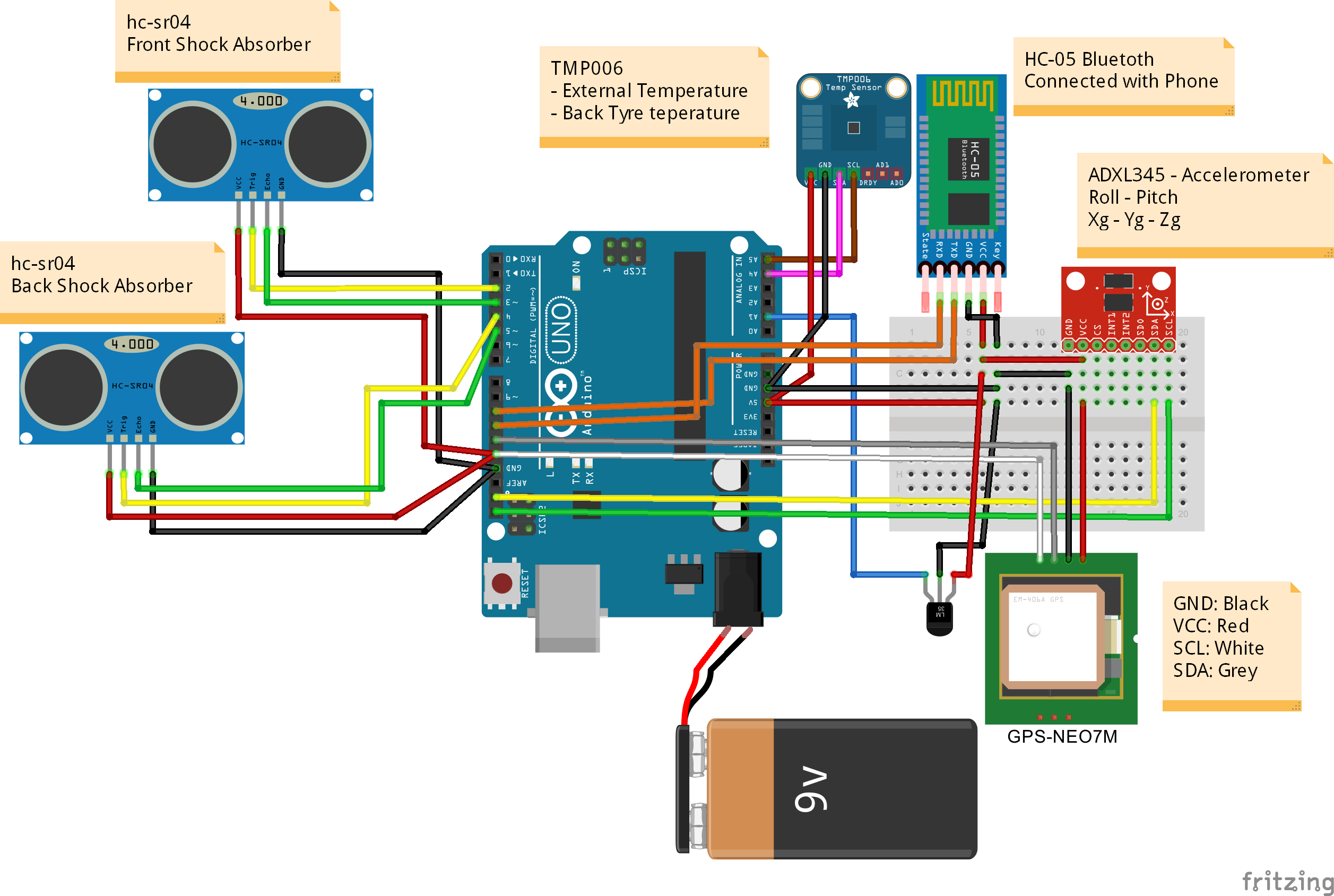
Minha configuração de hardware é composta de:
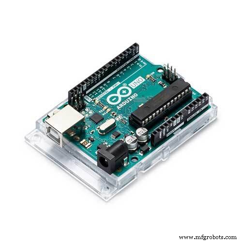
- 1 x Arduino Uno R3
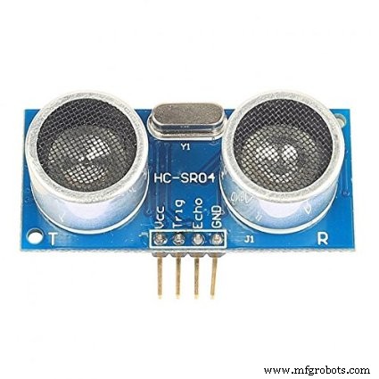
- 2 x módulo de alcance ultrassônico HC-SR04 , Usado para determinar a extensão do amortecedor (frente e verso)
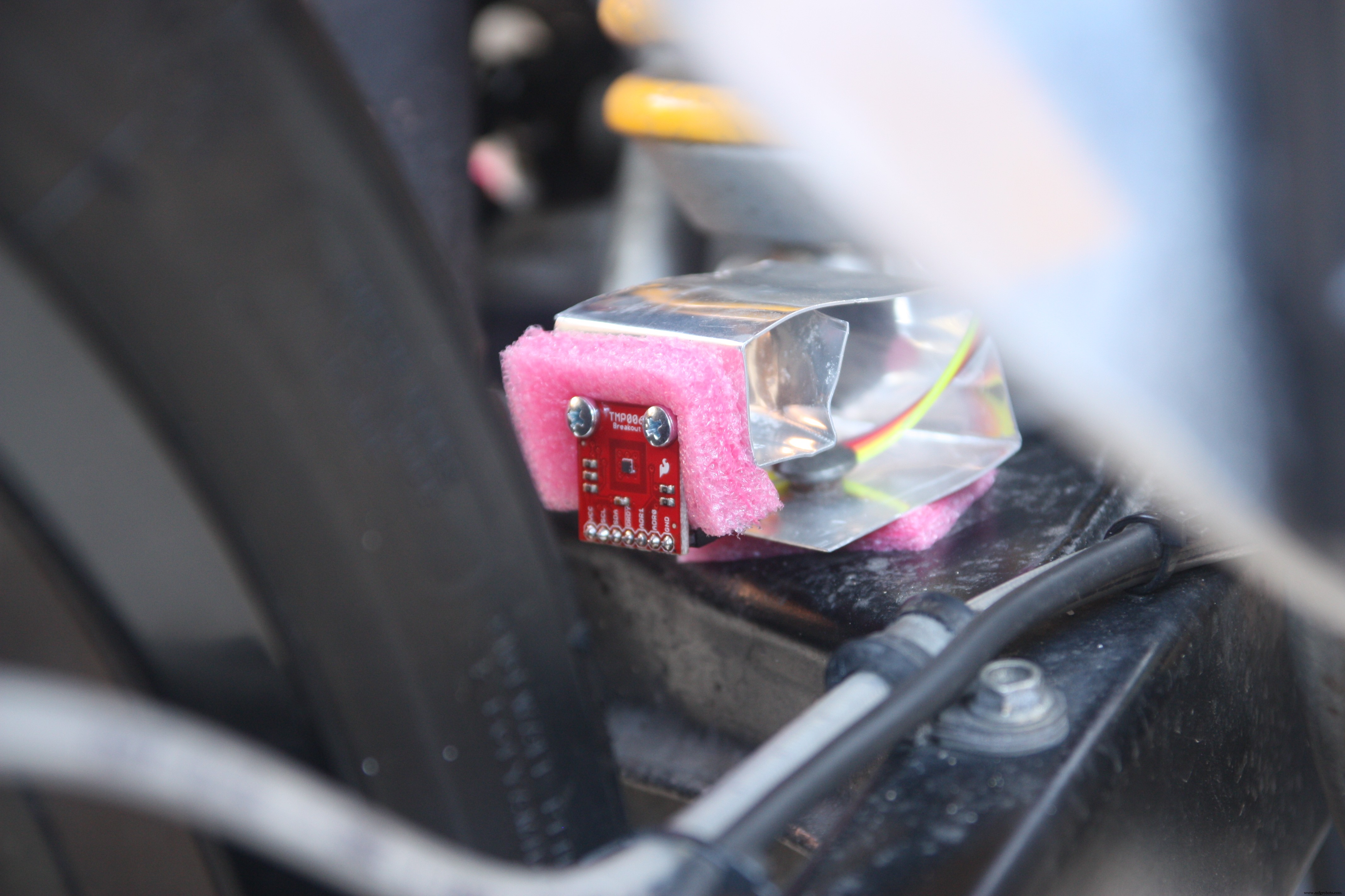
- 1 x sensor de temperatura sem contato termopilha infravermelho TMP006, usado para determinar a temperatura do pneu (também pode medir a temperatura externa - opcional)
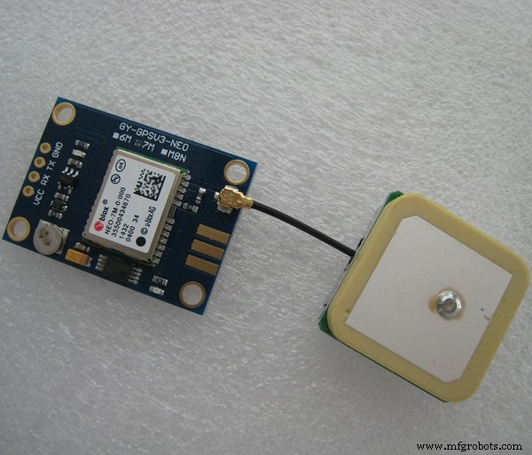
- 1 x GPS-NEO7M , usado para determinar a posição GPS, velocidade, altitude
- 1 x ADXL345 , Usado para avaliar a aceleração G em 3 eixos e calcular o ângulo de inclinação e o ângulo de Wheelie
- 1 x LM35DT a fim de determinar a temperatura externa
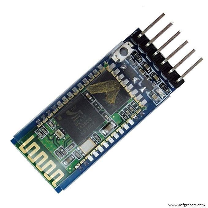
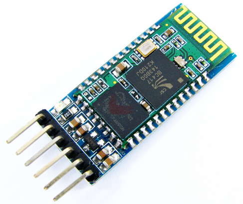
- 1 x HC-05 , módulo bluetooth, para se comunicar entre o arduino e o Windows Phone
- 1 x Fonte de alimentação (bateria genérica ou banco de energia para celular )
ETAPA 1 - Conectividade Bluetooth
Usei o SofwareSerial biblioteca para conectar o módulo bluetooth com o Arduino e habilitar a comunicação wireless com o Windows Phone.
A HC-05 O Módulo Bluetooth foi escolhido para este escopo, é um módulo bluetooth classe 2 com Perfil de Porta Serial, que pode ser configurado como Mestre ou Escravo.
A próxima etapa foi alterar o nome padrão do meu dispositivo Bluetooth, o nome padrão era HC-05 ... não era "atraente"
Como usar este dispositivo:
Em seu código Arduino:
- inclua o SoftwareSerial biblioteca
- definir a porta RX / TX
- inicialize a comunicação:
#include [...] SoftwareSerial BTSerial (10,11); // RX-TX [...] void setup () {BTSerial.begin (9600); [...]} Agora você está pronto para enviar via Bluetooth todas as strings que desejar usando a seguinte linha de comando:
... BTSerial.print ("Hello Hackster"); ... A comunicação entre o Windows Phone e o Arduino agora está pronta e foi muito fácil! ETAPA 2 - Comunicação GPS
O hardware usado para este osciloscópio foi um GPS-NEO7M módulo, é um módulo GPS de baixa potência que possui 56 canais e fornece atualizações de posição precisas a 10Hz.
A comunicação entre o Arduino e o Módulo GPS foi feita pelo SoftwareSerial Biblioteca e explorando uma biblioteca muito interessante chamada TinyGPS ++
Como se comunicar com este sensor:
- Defina a porta RX / TX
- inicialize o objeto TinyGPS
- inicialize a comunicação
Veja o código abaixo:
#include #include // Definir conexão serial com o GPSSoftwareSerial ss (12,13); // RX-TX // Definir um TinyGPS ObjectTinyGPSPlus gps; void setup () {// GPS Inizializess.begin (9600); [...]} void loop () {// Enquanto o GPS estiver disponível, leia as informações enquanto (ss .available ()> 0) {if (gps.encode (ss.read ())) {if (gps.location.isValid ()) {double lat =gps.location.lat (); double lon =gps.location .lng (); }}} [...]} ETAPA 3 - Acelerômetro
Para determinar os valores de aceleração nos 3 eixos e para calcular o ângulo de rotação e inclinação (ângulo Lean e Wheelie), usei um ADXL345
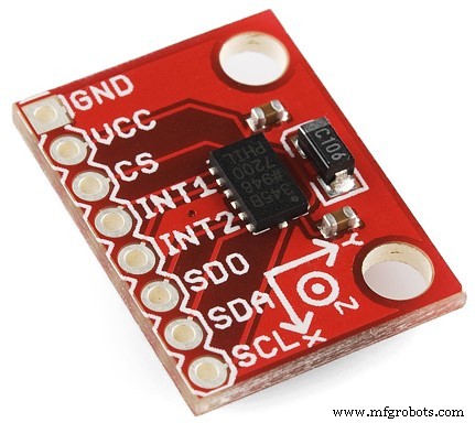
O ADXL345 é um acelerômetro de 3 eixos pequeno, fino e de potência ultrabaixa com medição de alta resolução (13 bits) de até ± 16 g. Os dados de saída digital são formatados como complemento de dois de 16 bits e podem ser acessados por meio de um SPI (3 ou 4 fios) ou I2C interface digital.
A comunicação entre o Arduino e o sensor ADXL345 acontece usando o ADXL345.h Biblioteca.
É muito importante entender que ao conectar este sensor poderá determinar a aceleração da gravidade nos 3 eixos mas os valores não são calibrados imediatamente. Você precisa criar um código para definir o OFFSET.
Decidi determinar o "ponto zero" no primeiro loop. Para fazer isso, a aceleração G no primeiro loop será os valores de referência que você terá que subtrair para as medições subsequentes.
// primeiro loop para if (i ==0) {refXg =Xg; refYg =Yg; refZg =Zg; i =1;} // subtraia o ponto zeroXg =Xg - refXg; Yg =Yg - refYg; Zg =Zg - refZg + 1; Então você tem que calcular o ângulo de inclinação e o ângulo de Wheelie com base nos componentes de aceleração g.
Abaixo, você pode ver as 2 equações matemáticas simples para fazer isso:
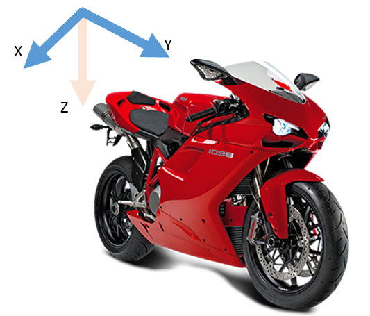
// Roll &Pitch Equationsroll =- (atan2 (-fYg, fZg) * 180.0) / M_PI; pitch =(atan2 (fXg, sqrt (fYg * fYg + fZg * fZg)) * 180.0) / M_PI; Neste projeto, você deve considerar:
- O eixo Z são os eixos de gravidade natural
- O eixo Y é a direção do movimento
- O eixo X é o movimento lateral
Como se comunicar com este sensor:
- inicialize o objeto ADXL345
- inicialize a comunicação
Agora que você está pronto para ler as informações de aceleração, veja o código abaixo:
#include #include #include // Definir conexão serial com o GPSSoftwareSerial ss (12,13); // RX-TX // Definir um ADXL345 ObjectADXL345 acc; void setup () {// ADXL345 Inizializeacc.begin (); [...]} void loop () {// Ler os componentes de aceleraçãodouble Xg, Yg, Zg; acc.read (&Xg, &Yg, &Zg);} ETAPA 4 - Temperatura do pneu
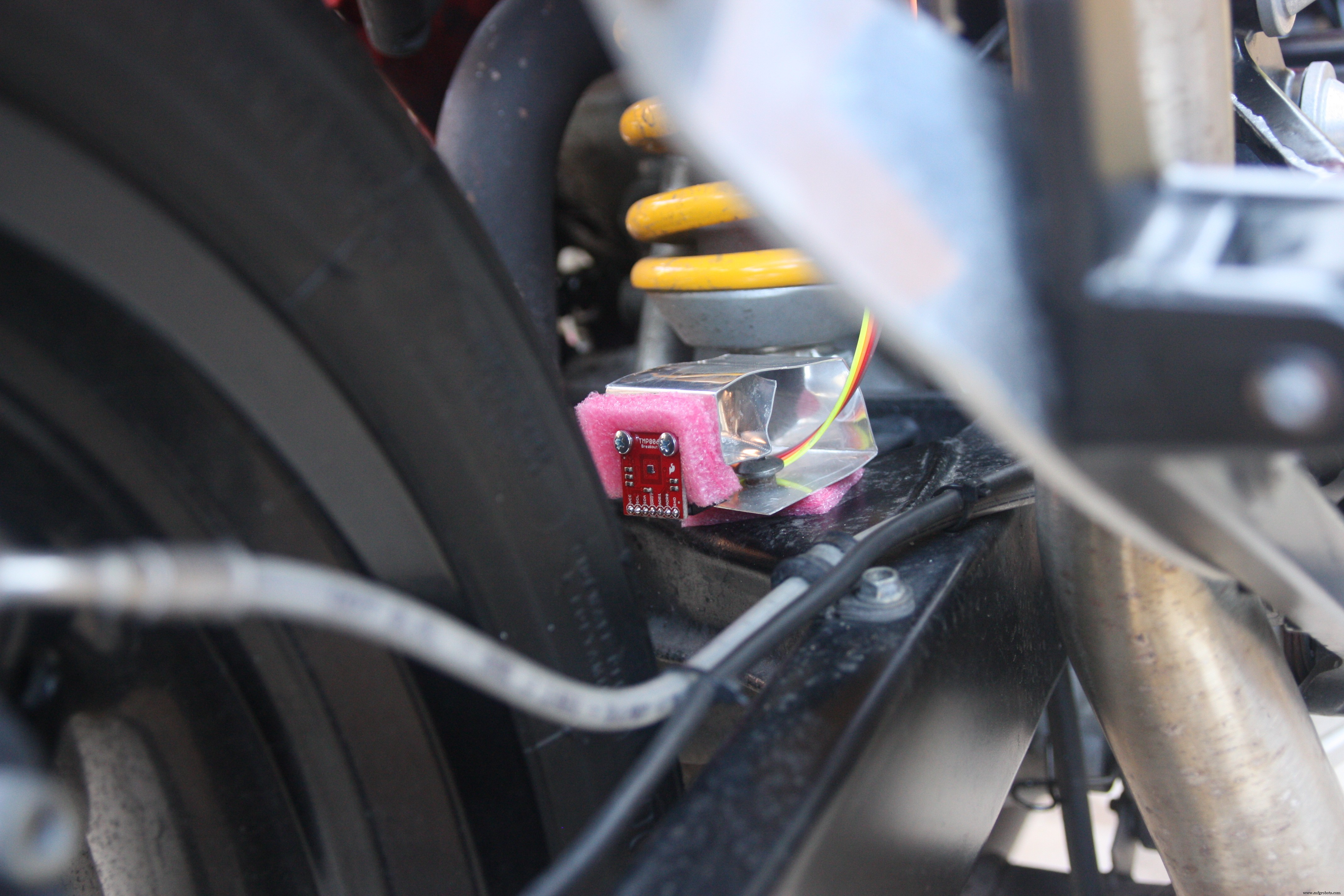
Para determinar a temperatura do pneu, precisei de um sensor que por motivos óbvios não toca no pneu. a única maneira é usar um sensor de temperatura infravermelho. Para isso decidi usar um TMP006 sensor
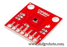
Os TMP006 são sensores de termopilha MEMs totalmente integrados que medem a temperatura de um objeto sem ter que estar em contato direto. A termopilha absorve energia infravermelha passiva de um objeto em comprimentos de onda entre 4 um para 16 um dentro do campo de visão definido pelo usuário final.
A mudança correspondente na voltagem através da termopilha é digitalizada e relatada com a medição do sensor térmico da matriz no chip por meio de um I2C
Agora a questão é:onde devo posicionar meu sensor? Olhando a ficha técnica você encontrará informações importantes sobre a distância recomendada entre o sensor e o objeto.
Você deve observar a regra de que a distância deve ser menor que a metade do raio do ângulo sólido do objeto.
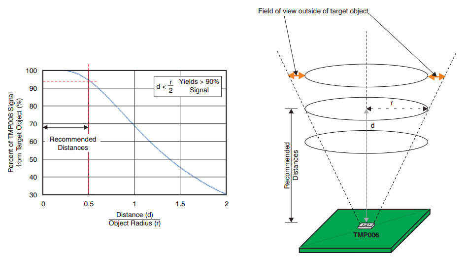
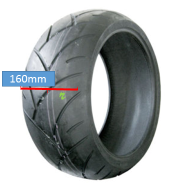
em outras palavras, a largura do meu pneu é 160 mm, a meia largura será o raio (R) do ângulo sólido, então o resultado final de R será 80 mm. Portanto, a distância recomendada será de 40 mm (ou menos), é igual a R / 2
A comunicação entre o Arduino e o TMP006 é feito usando o SerialSoftware biblioteca e Adafruit_TMP006.h biblioteca
#include #include "Adafruit_TMP006.h" / Variáveis para funções TMP006 ************************** ************** / Adafruit_TMP006 tmp006; void setup () {} void loop () {// Ler o objeto IR temperatura float objt =tmp006.readObjTempC (); // Ler a temperatura do sensor ( Temperatura externa) float diet =tmp006.readDieTempC ();} ETAPA 5 - Temperatura externa
O valor da temperatura externa foi determinado usando e LM35 sensor (pacote DT).
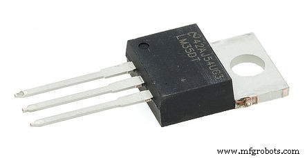
A série LM35 são dispositivos de temperatura de circuito integrado 1 de precisão com uma tensão de saída linearmente proporcional à temperatura centígrada.
Cada grau centígrado produz um aumento / diminuição da tensão de 10 mV
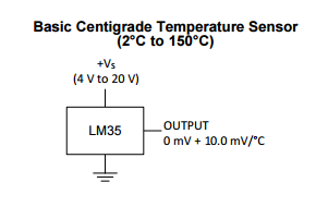
O valor do sensor foi determinado lendo a entrada analógica do Arduino (AI)
int TempExtPin =A1; // selecione o pino de entrada float celsius =0, farhenheit =0; // variáveis de temperaturafloat millivolts; sensor interno; [...] sensor =analogRead (TempExtPin); // Lê LM35 valuemillivolts =(sensor / 1023.0) * 5000; // saída em milivolts Voltagecelsius =milivolts / 10; ETAPA 6 - Posição ultrassônica
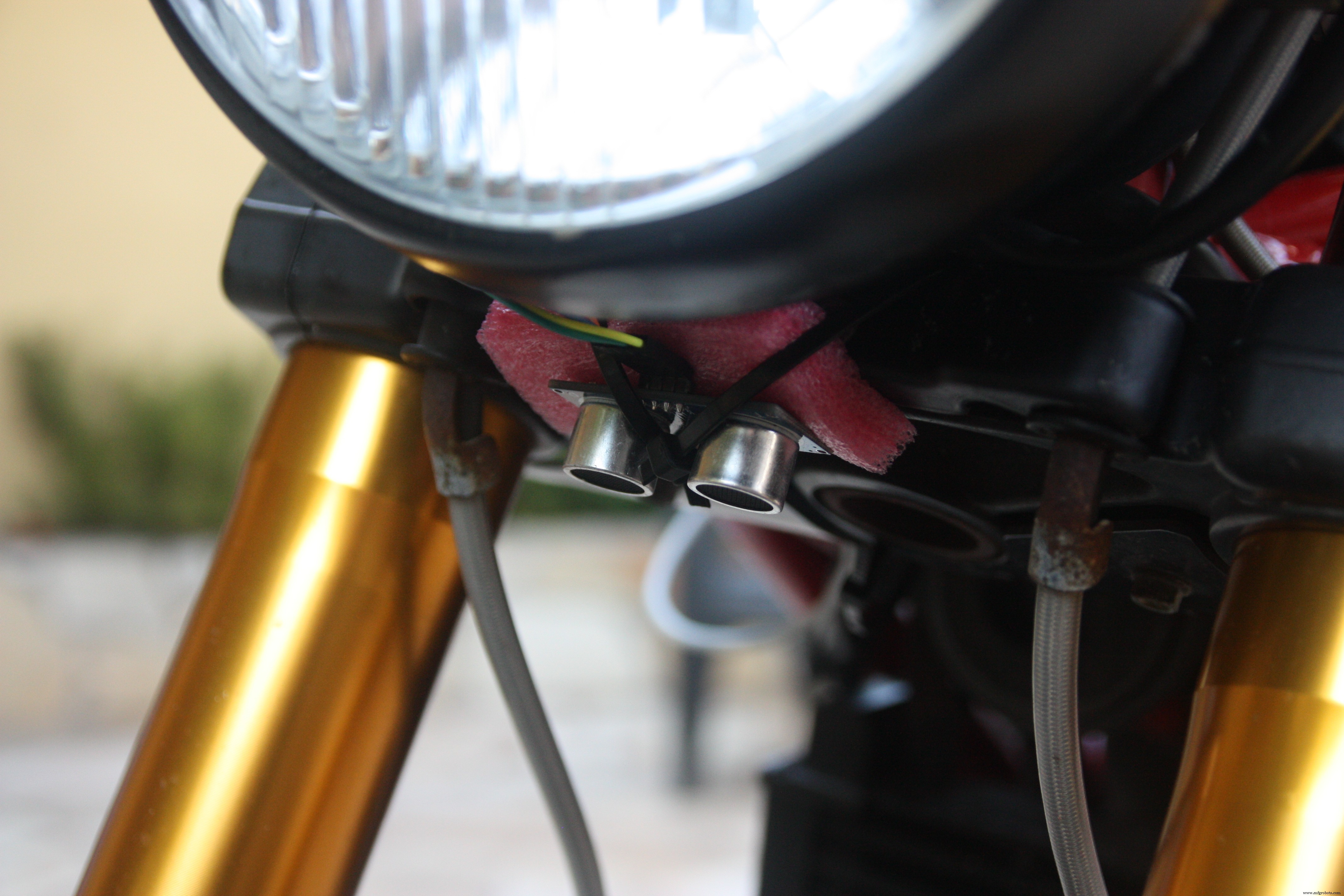
O objetivo do uso deste sensor é determinar a escursão das suspensões da motocicleta.

O HC-SR04 medir o tempo que as ondas sonoras levam para voltarem depois de encontrar um obstáculo. O feixe de ondas sonoras emitido tem formato cônico e o mesmo se aplica às ondas refletidas por um obstáculo.
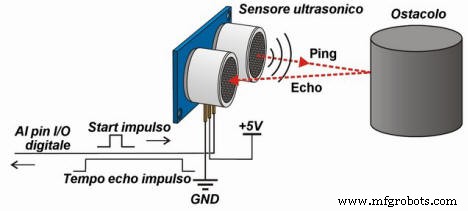
A velocidade das ondas sonoras no ar a 20 ° C é de cerca de 343,4 m / s, neste exemplo, para simplificar, consideraremos o valor aproximado de 340 m / s .
Considerando a lei cinemática S =V x t (onde S:espaço ou deslocamento do objeto, V:velocidade, t:tempo) podemos anunciar que, em nosso caso, a distância é S =0,034 x T .
Temos que dividir o tempo por 2 porque o tempo que convertemos é aquele usado para ir e voltar pelas ondas, a fórmula final onde t é o tempo retornado do sensor em cm / microssegundo é:
S =0,034 x t / 2
Abaixo você pode ver um exemplo que você pode tentar usar para determinar a distância do objeto.
digitalWrite (triggerPort, LOW); // Envia pulso de 10 microssegundos para triggerdigitalWrite (triggerPort, HIGH); delayMicroseconds (10); digitalWrite (triggerPort, LOW); longa duração =pulseIn (echoPort, HIGH); r longo =0,034 * duração / 2; O código acima descreve bem como o sensor funciona, mas você descobrirá que este código é muito lento e mal executado .
Para este projeto, decidi experimentar a nova biblioteca chamada NewPing.h para obter mais detalhes, visite este link e veja o código Arduino completo do projeto.
Use o NewPing.h biblioteca é muito fácil.
- Inclua a biblioteca
- definir o gatilho e porta de eco do HC-SR04
- inicializa o objeto
- chame a função ReadPositionPing.
#include / ************************************* ******* Definir variáveis para funções HC RS04 ************************************** ****** /// HC-RS04 portsint triggerPort =2; int echoPort =3; // NewPing configuração de pinos e distância máximaNewPing sonar (triggerPort, echoPort, 200); void setup () {} void loop () {/ *** READ POSITION *** / int Pos =ReadPositionPing ();} int ReadPositionPing () {unsigned int uS =sonar.ping (); return sonar.convert_cm (uS);}
O software UWP
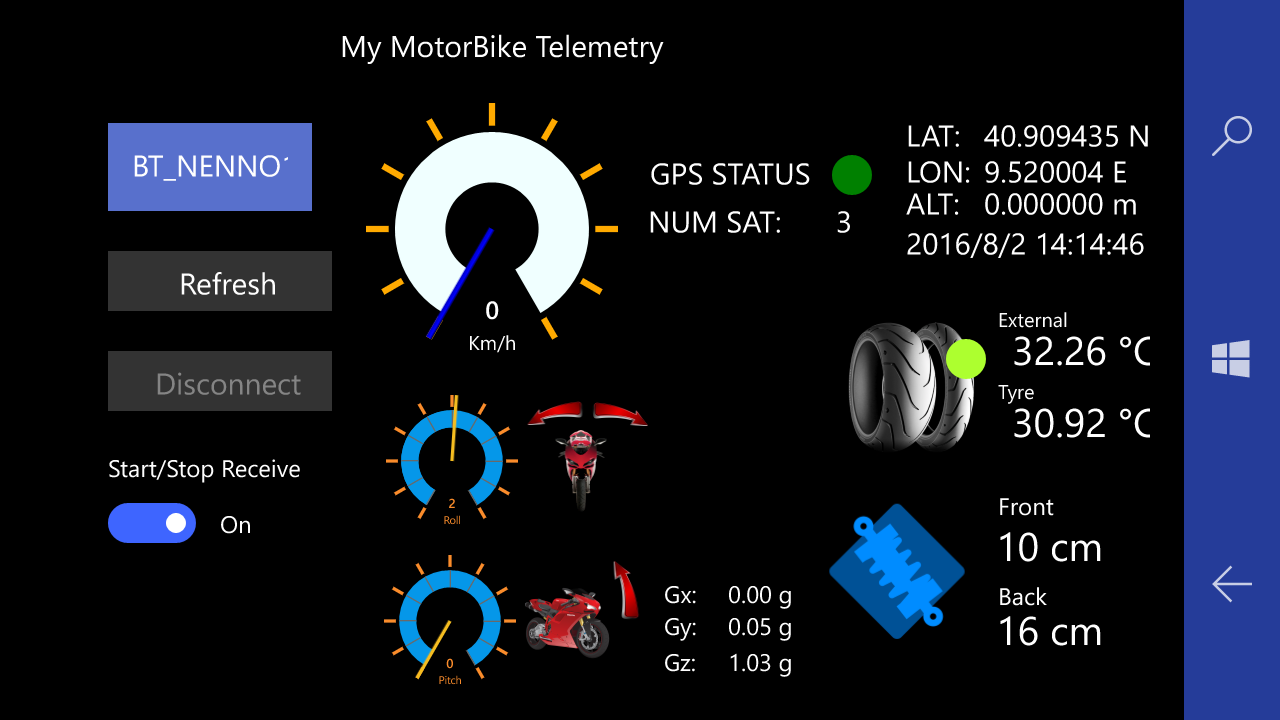
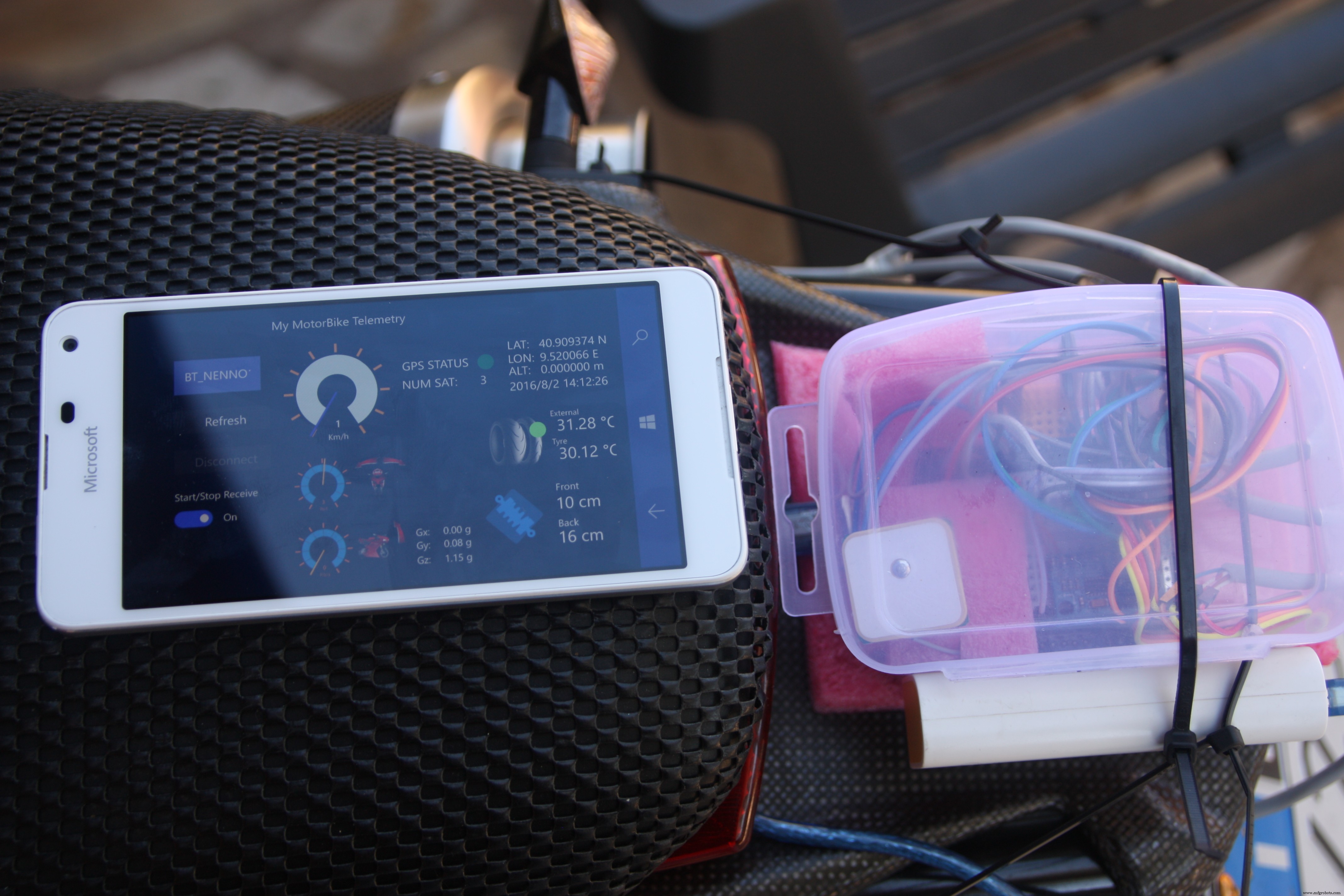
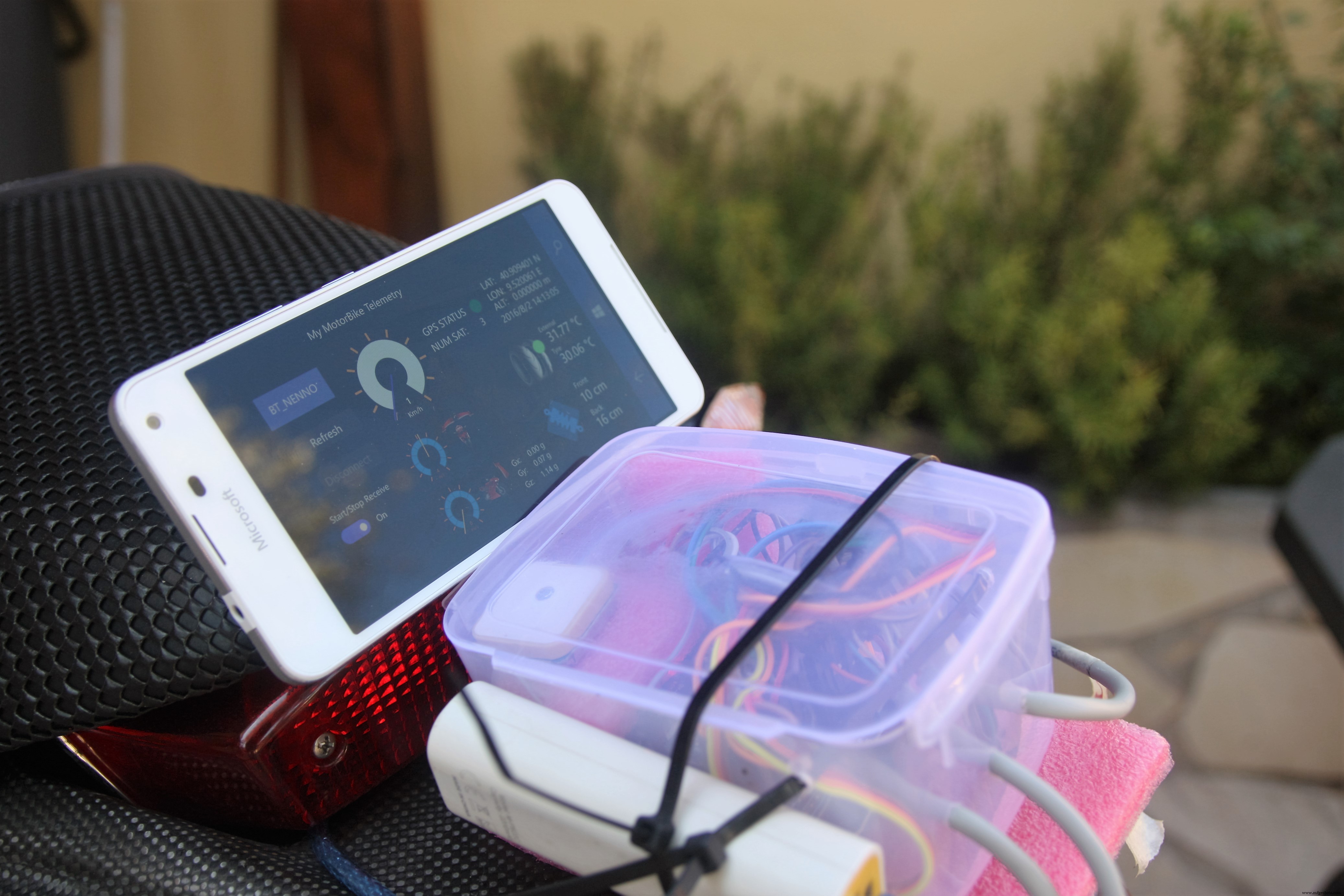
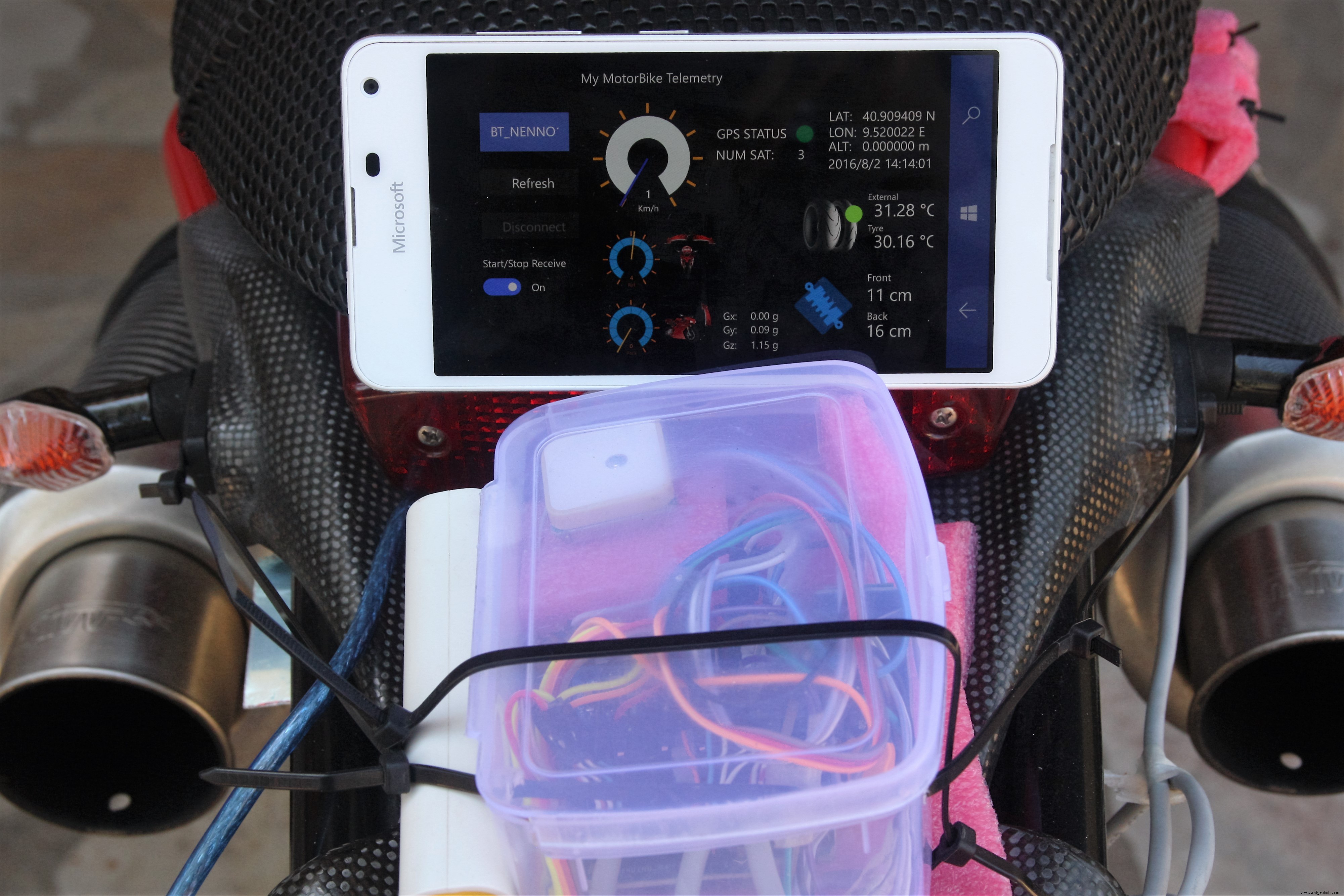
O software consiste em uma interface de usuário conectada à unidade de controle via bluetooth. A IU mostra todos os dados enviados do Arduino e enviados para IoTHub os valores do sensor.
A comunicação serial entre o Arduino e a UWP é interpretada pela leitura da string de entrada.
Cada string recebido é validado verificando que contém o START e END marcadores. Se a string de entrada estiver formatada corretamente, o aplicativo irá cuspir as informações e mostrá-las na interface do usuário do aplicativo.
Abaixo você pode ver um exemplo de uma string enviada do Arduino que contém os marcadores START / END, esta string será dividida pelo caractere "tubo" para determinar os valores de cada sensor:
$ START | 40,909409 | N | 9,520008 | E | 8 | 2 | 2016 | 15:46:42 | 0,09 | 0,000000 | 0 | 0 | -0,21 | 0,00 | 0,00 | -0,02 | 0,98 | - | 0,00 | 35,19 | 29,58 | 16 | 10 | $ END | abaixo da definição de Array após a divisão da string enviada:
- Posição 0 - Marcador START
- Posição 1 - Latitude
- Posição 2 - N (Nord)
- Posição 3 - Longitude
- Posição 4 - E (Leste)
- Posição 5 - mês
- Posição 6 - dia
- Posição 7 - ano
- Posição 8 - hh:MM.ss
- Posição 9 - velocidade (Km / h)
- Posição 10 - altitude (m)
- Posição 11 - satélites (número de satélites)
- Posição 12 - hdop (número de satélites em uso)
- Posição 13 - rolar
- Posição 14 - arremesso
- Posição 15 - Xg
- Posição 16 - Yg
- Posição 17 - Zg
- Posição 18 - Áudio ( Opcional - atualmente desabilitado )
- Posição 19 - Distância (m)
- Posição 20 - Temperatura (temperatura externa por LM35)
- Posição 21 - Temperatura do pneu (temperatura do pneu de TMP006)
- Posição 22 - Amortecedor dianteiro (cm)
- Posição 23 - Amortecedor traseiro (cm)
- Posição 24 - Marcador END
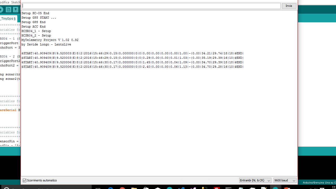
pelo "Serial Monitor" do Arduino IDE você pode ver como o Arduino Code funciona:
Para gerenciar todos os dados enviados da unidade central via Bluetooth, desenvolvi um aplicativo universal do Windows que é um bom exemplo do poder do UWP. Como você sabe, UWP é uma plataforma que permite executar o aplicativo em todas as famílias de dispositivos com Windows 10 integrado.
A interface do usuário é muito simples e intuitiva, no lado esquerdo você pode ver o recurso de conexão Bluetooth, no meio 3 medidores usados para mostrar a velocidade, ângulo de inclinação e ângulo de Wheelie. Todos os componentes G são mostrados e, à direita, informações sobre a posição GPS, temperaturas e excursões do amortecedor.
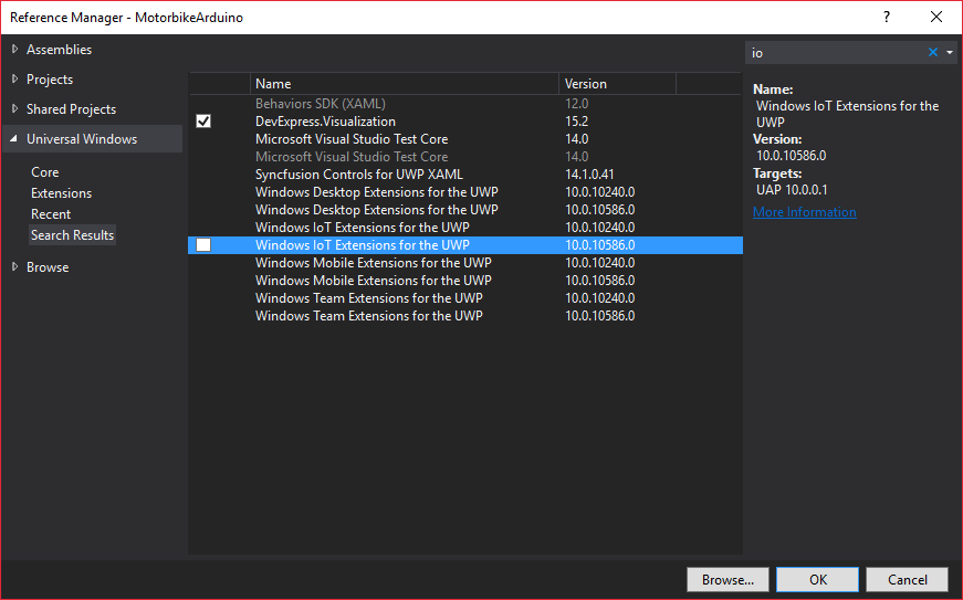
Como implantar o aplicativo no Windows 10 Mobile?
Com o Windows 10 SDK Preview Build 10166, a Microsoft apresentou a ferramenta Windows 10 Application Deployment (WinAppDeployCmd.exe).
O Windows 10 Application Deployment (WinAppDeployCmd) é um utilitário de linha de comando que pode ser utilizado para implantar um aplicativo Universal do Windows de um PC com Windows 10 para qualquer dispositivo móvel do Windows 10. Ele permite que os usuários implantem um arquivo .AppX em um dispositivo conectado por USB ou disponível na mesma sub-rede sem exigir acesso à solução Visual Studio completa.
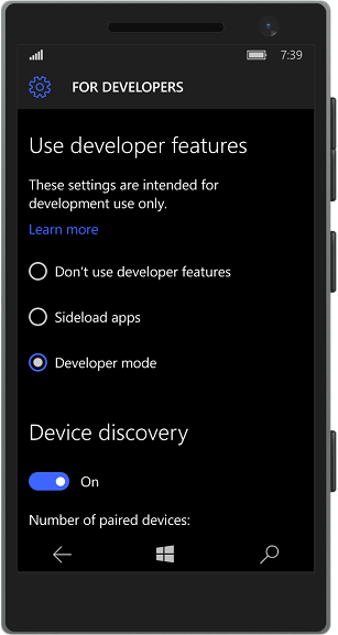
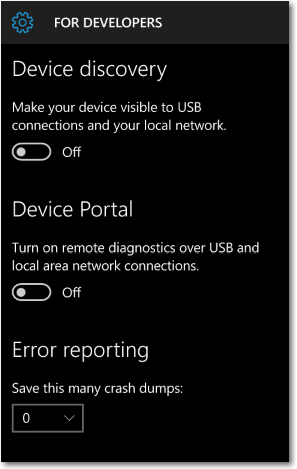
ETAPA 1:
Em primeiro lugar, mova seu dispositivo móvel no "Modo de desenvolvedor" (vá para ATUALIZAÇÃO E SEGURANÇA => PARA DESENVOLVEDOR )
depois disso, conecte seu dispositivo via USB e torne-o visível a conexão USB (um código PIN será retornado)
ETAPA 2:
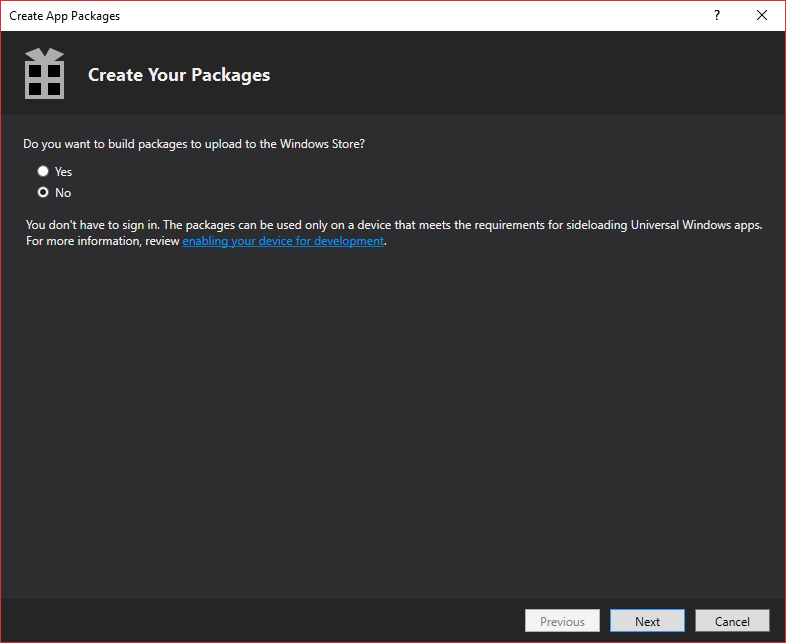
Clique com o botão direito em seu Projeto => Loja => Criar pacotes de aplicativos
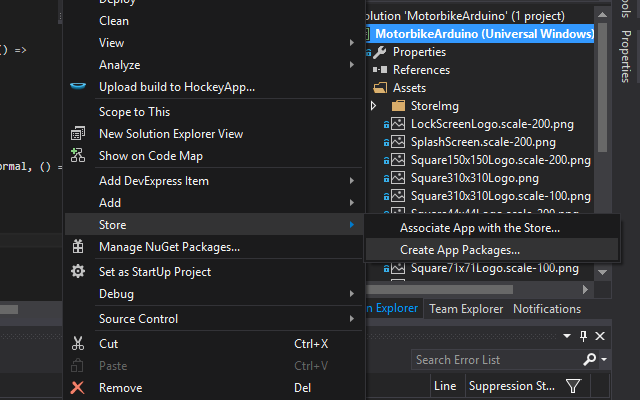
ETAPA 3:
No assistente Criar pacotes de aplicativos, selecione NÃO Se você deseja criar um pacote local e clique em PRÓXIMO . Depois disso, escolha as plataformas de processador a serem almejadas. Para nosso propósito, escolha a plataforma ARM e clique em CRIAR .
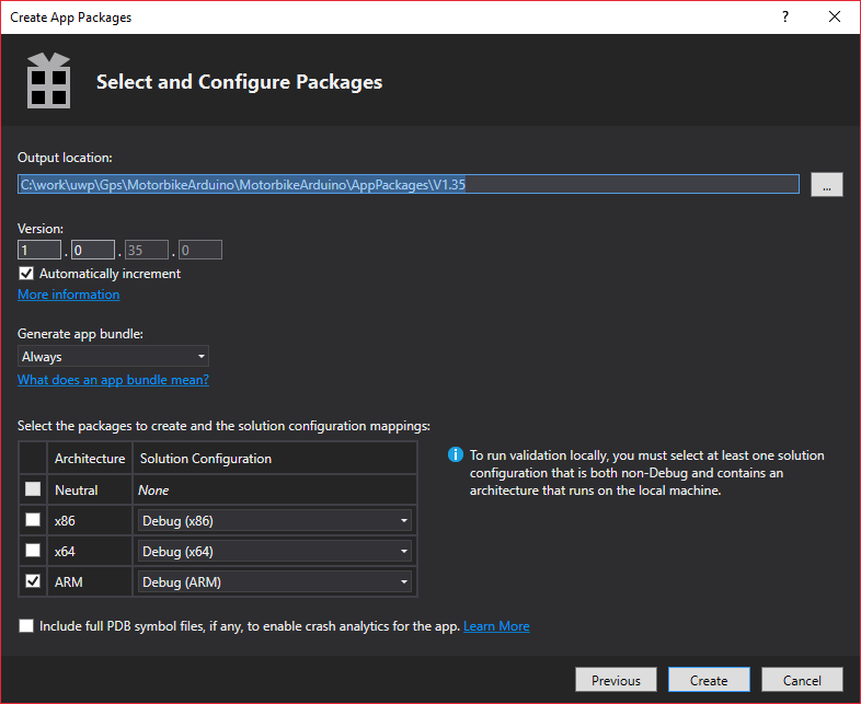
No final do processo de criação, o assistente fornece uma URL local onde o pacote foi criado.
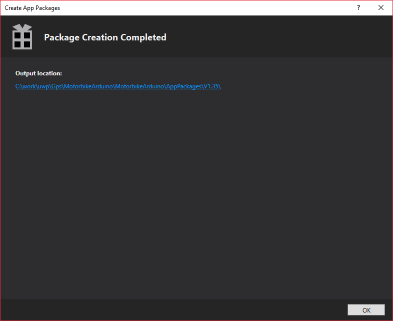
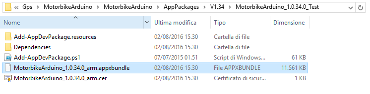
abrindo a url você encontrará o arquivo Appx disponível para ser implantado no dispositivo.
ETAPA 4:
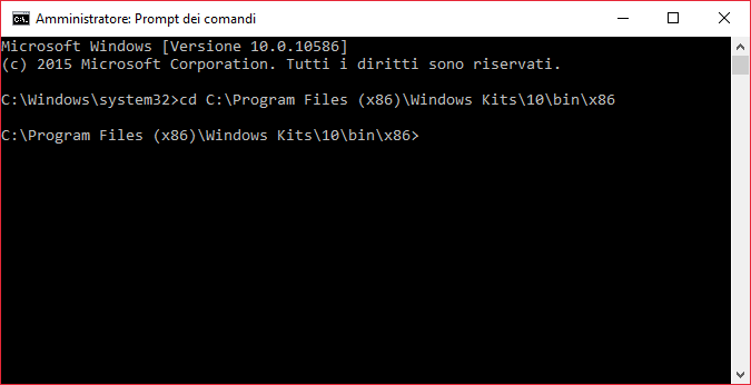
Abra um prompt de comando e mova o foco para C:\ Arquivos de programas (x86) \ Windows Kits \ 10 \ bin \ x86 \
e digite a seguinte linha de comando
WinAppDeployCmd install -file "C:\ work \ uwp \ Gps \ MotorbikeArduino \ MotorbikeArduino \ AppPackages \ V1.35 \ MotorbikeArduino_1.0.35.0_Debug_Test \ MotorbikeArduino_1.0.35.0_arm_Debug.appx / 127.0" código> AAA123
(onde AAA123 é o código PIN retornado do seu telefone conectado ao USB no modo de associação)
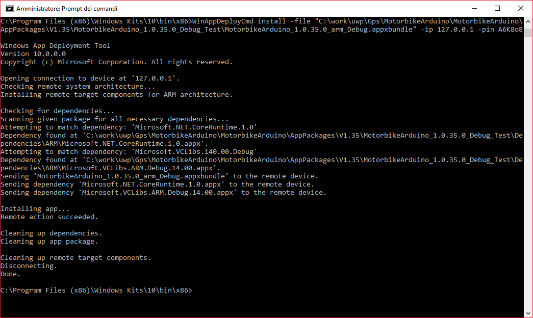
At the end of the process the application will be installed in your device and you will be able to "pin to start":

AZURE
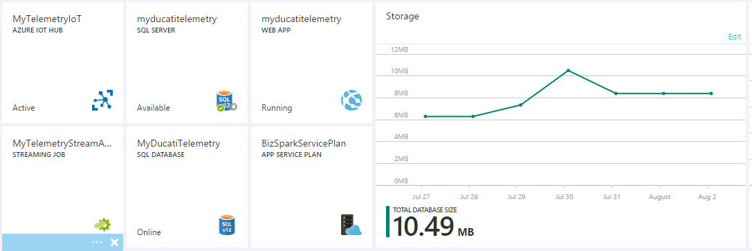
Now we are ready to describe how to configured the Azure services. For this project will be necessary to create:
- WebApp + SQL Azure
- IoTHUB
- Stream Analytics JOB
- A DeviceId that will be used to send data to IoTHUB .
OK GO! Do you have an AZURE account?
- If NO, please go to https://azure.microsoft.com/ and create one.
- If YES... GOOD! Go to https://portal.azure.com
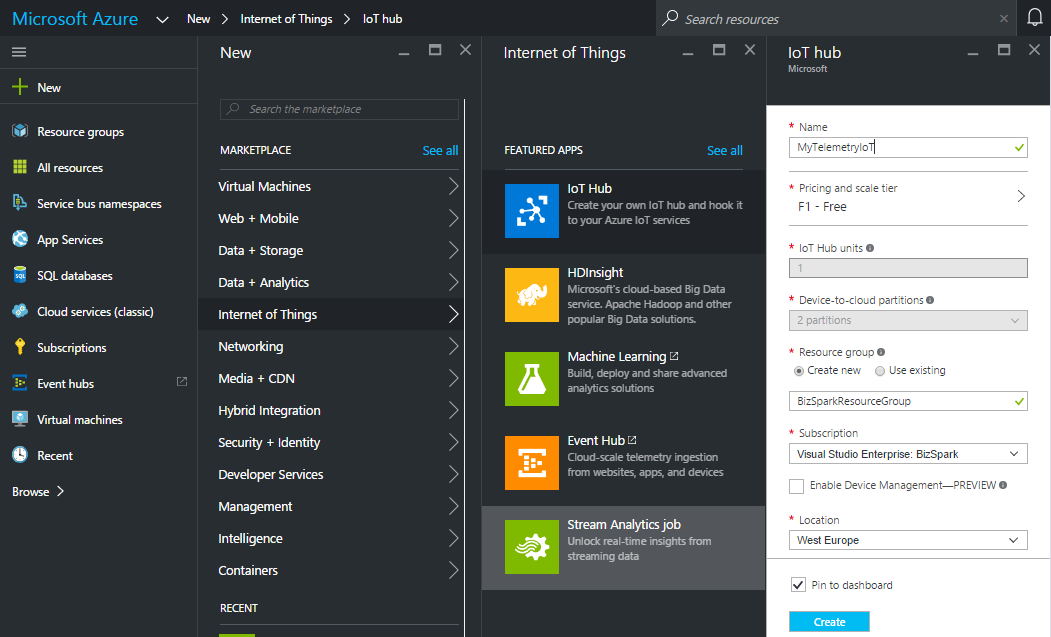
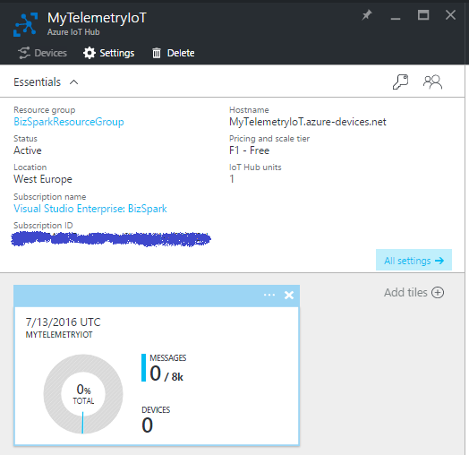
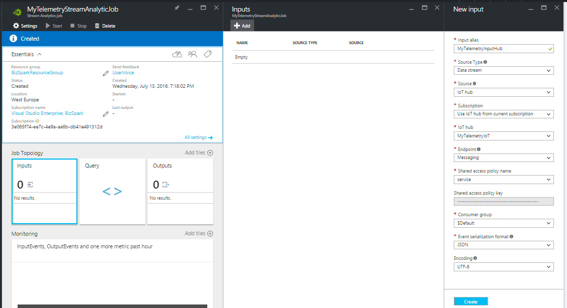
STEP 1 - Create and configure IoT Hub:
The IoTHUB is the access point of the telemetry values to the Cloud.
Create your IoTHub, Click on New => Internet of Think => IoT Hub and compile the Hub fields and click Create
Subsequently, in your Azure dashboard, you may see the IoT HUB deploying and after some seconds your IoT HUB will be ready.
Click on the new tile in your dashboard and go to All settings blade.
See your IotHub Hostname and make a note:
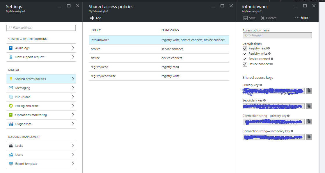
In the Shared access policies blade, click the iothubowner policy, and then copy and make note of the connection string in the iothubowner lâmina
Ok...your Iot hub has been created successfully, you are almost ready to use it!
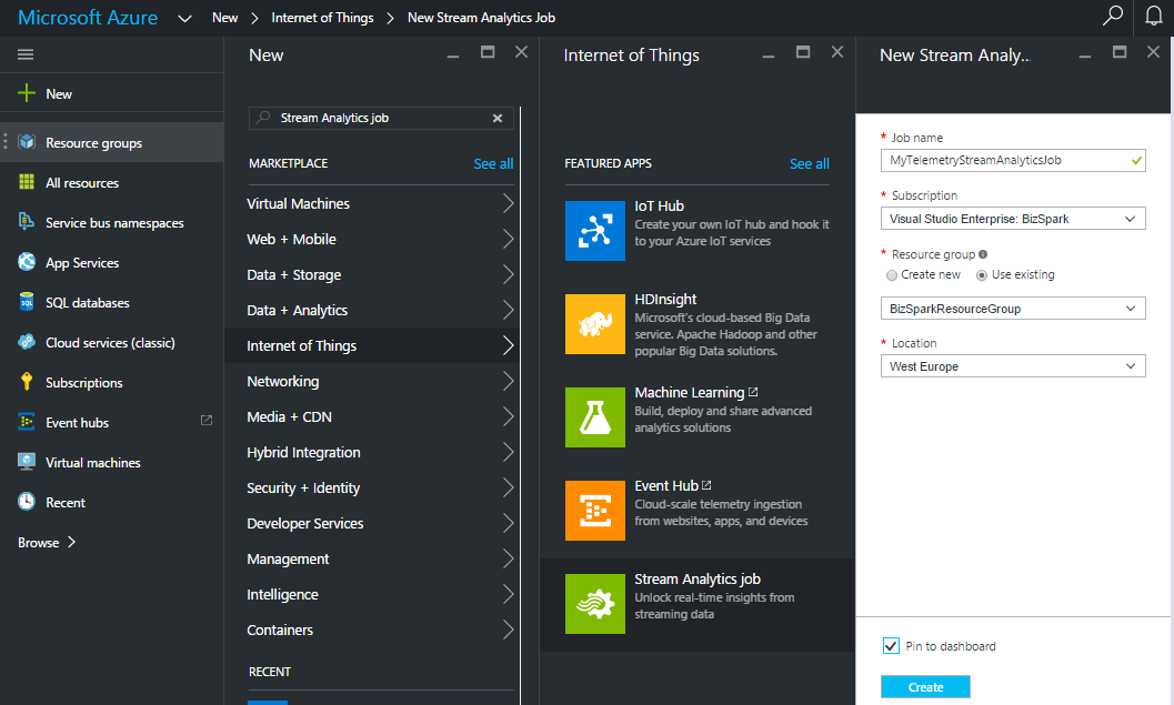
STEP 2 - Create and configure Stream Analytic
The stream Analytics has the purpose of read and write all data sent to the IoTHUB and save them into a database table.
Create a new Stream Analytics job:
Click on New => Internet of Think => Stream Analytics job
Compile all fields and click on Create button.
Now we are ready to configure Input/Output and the query of the streamAnalityncs JOB.
Set up Input - Select the Source . In our case the source will be the IoTHub
Setup the Output - Select the destination. In our case the output will be a table of the SQL Azure database (I'll show you how to create a sql db in the next step)
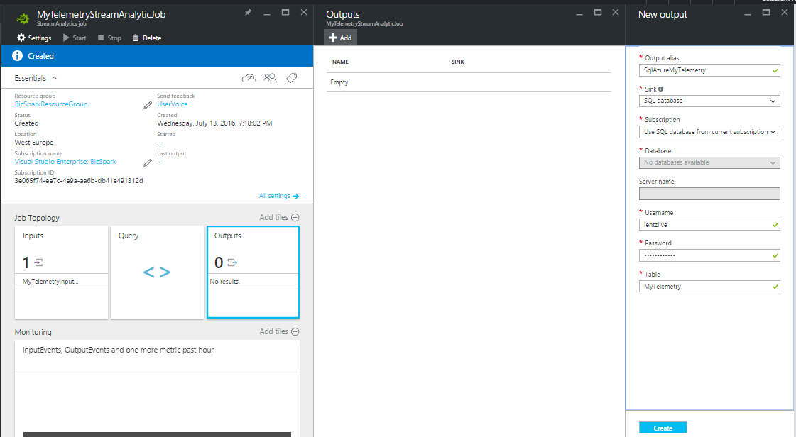
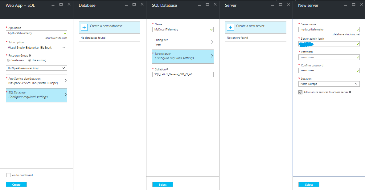
STEP 3 - Create WebApp + SQL Azure
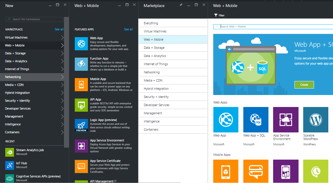
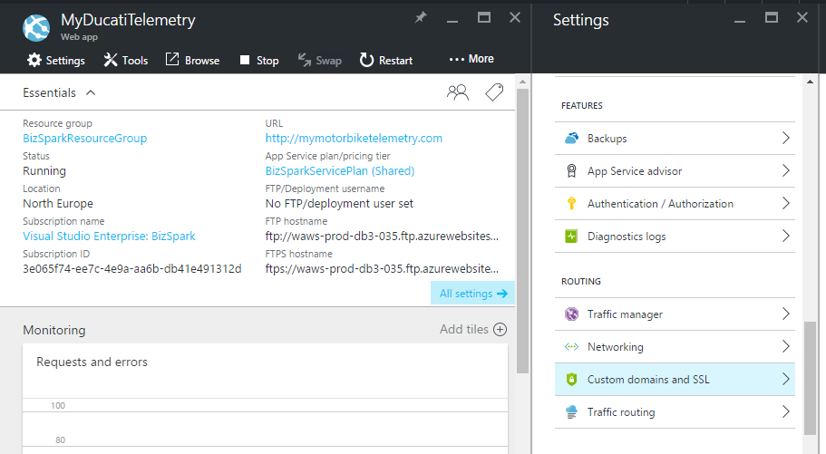
Go to dashboard and select WebApp+SQL (New => Networking => Web + Mobile => Web App + Sql )
Now configure your webapp compiling the following fields:
- App Name
- Choose a subcription
- Choose a Resources Group ( if you don't have one create your first Resources Group)
- Choose an App Service Plan and a pricing tier (for this example you can considerer to choose a F1 free plan)
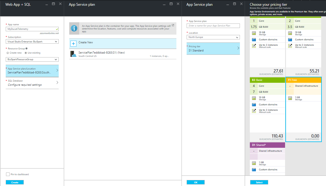
Configure your SQL, create a new one and choose the name , pricing tier , server name and add Admin Login credentials :
Now back to the STEP 2 , we are now ready to create the StreamAnalitycs Query. Click on StreamAnalyticJob tile and select "Query". Insert your query in the right panel.
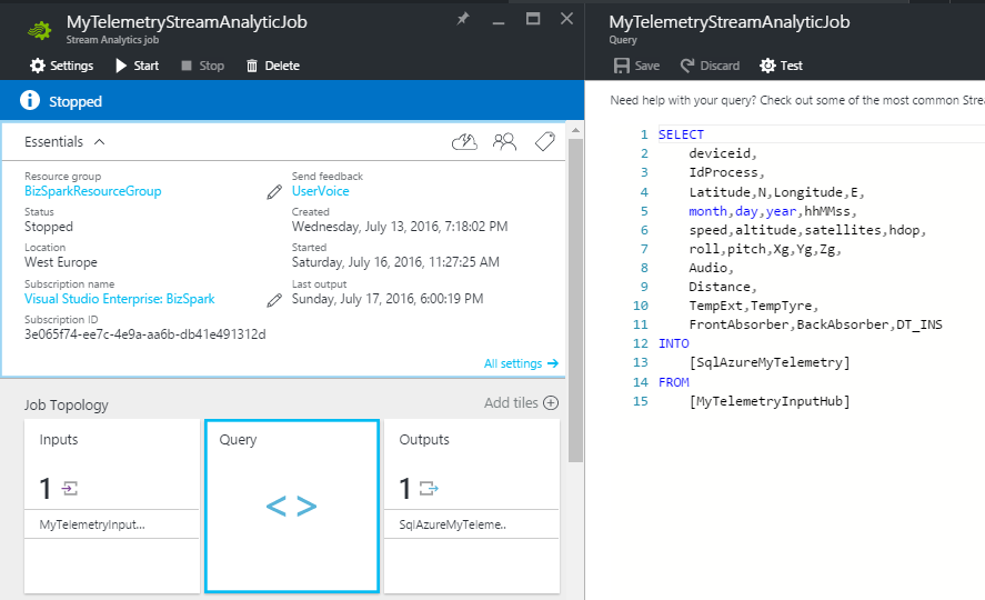
As you can see, the query describes the process workflow. Catch the data from "MyTelemetryInputHub" and save them into "SqlAzureMyTelemetry" ... easy&wonderful!!
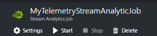
At the end, we have only to start the JOB clicking the START botão.
Create a DeviceId for HUB
This step is necessary in order to create a connection between my device and the IoTHUB. We need to create a new device identity and add into the ID registry of the IoT HUB.
For more information please visit the follow link
To generate a new one deviceId, you have to create a Console Application in Visual Studio.
In the NuGet Package Manager window, search and install the Microsoft.Azure.Devices pacote.
Add the below code In your Console application, replace your IoTHub Connection String and chose a deviceId alias (in my case the deviced is MyDucatiMonsterDevice )
class Program{//Install-Package Microsoft.Azure.Devicesstatic RegistryManager registryManager;// Connection String HUBstatic string connectionString ="xxxxxxxxxxxxxx";static void Main(string[] args){registryManager =RegistryManager.CreateFromConnectionString(connectionString);AddDeviceAsync().Wait();Console.ReadLine();}// creates a new device identity with ID myFirstDeviceprivate async static Task AddDeviceAsync(){ string deviceId ="myDucatiMonsterDevice";Device device;try{device =await registryManager.AddDeviceAsync(new Device(deviceId));}catch (DeviceAlreadyExistsException){device =await registryManager.GetDeviceAsync(deviceId);}Console.WriteLine("Generated device key:{0}", device.Authentication.SymmetricKey.PrimaryKey);}}
Run the console application (press F5) and generate your device key!
WEB application
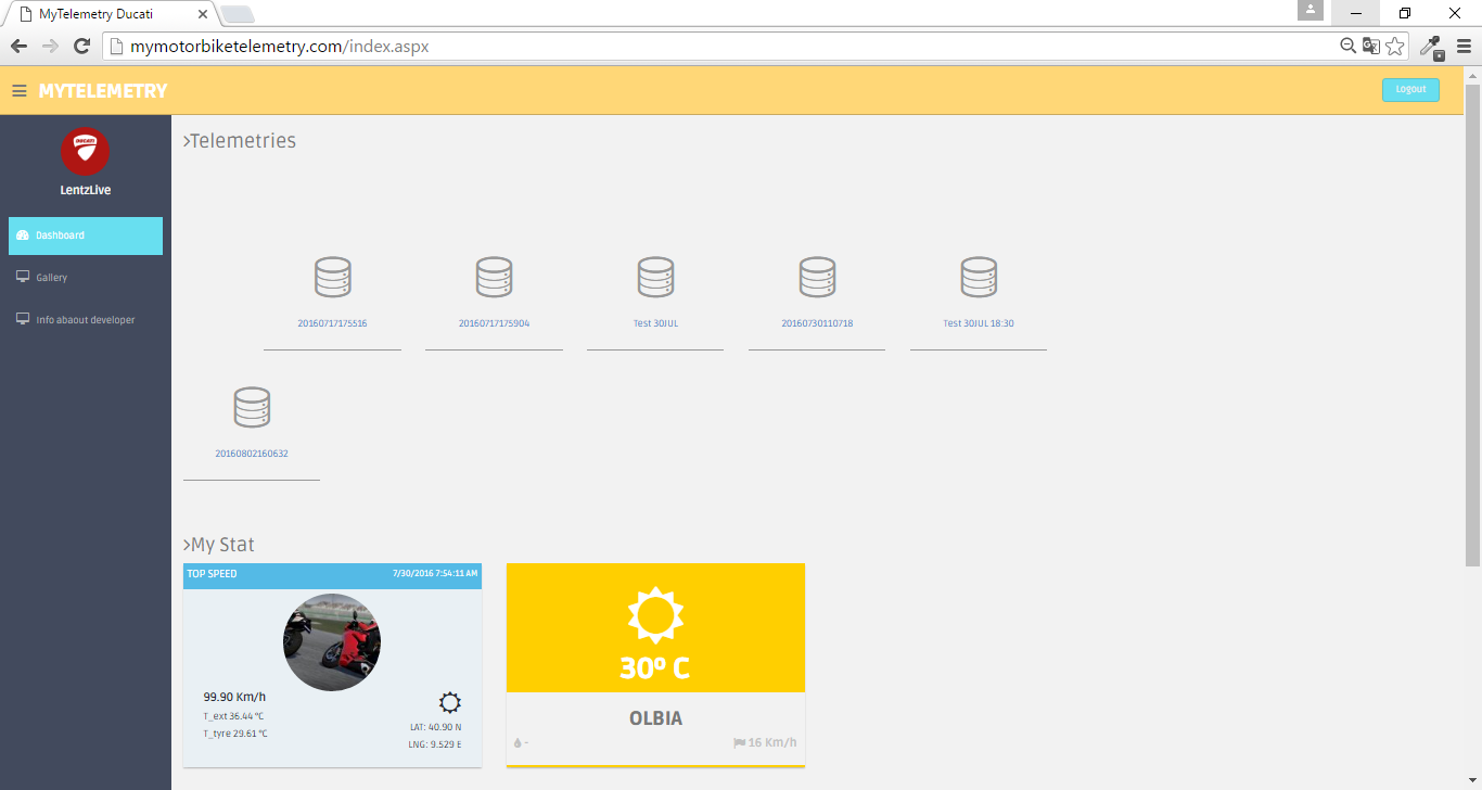
At this point of the project i thinked about how can i see my telemetry data and how can i show them to my friends and share the results on the social media. to do that I decided to create a responsive web site in ASP .NET
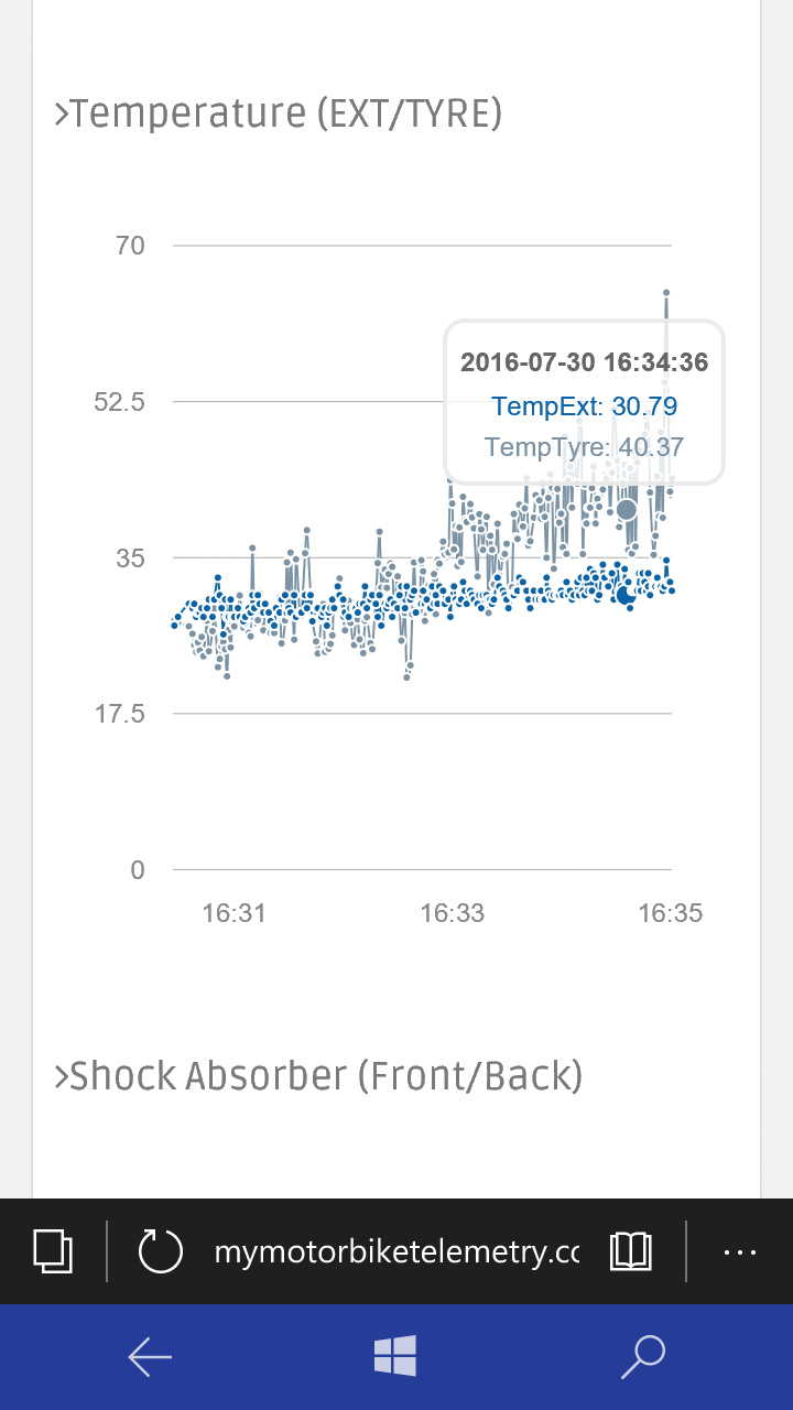
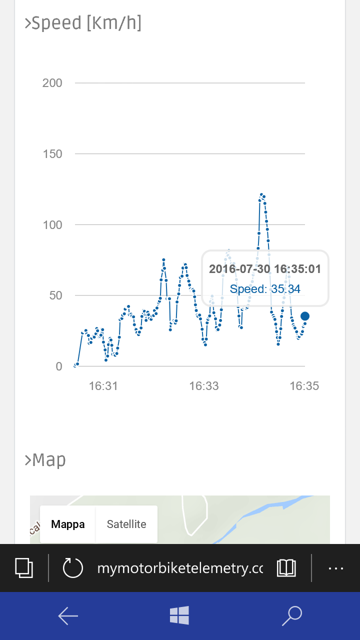
The website consist in a dashboard contains all my telemetries. The data has been read using the Entity framework from SQL Azure.
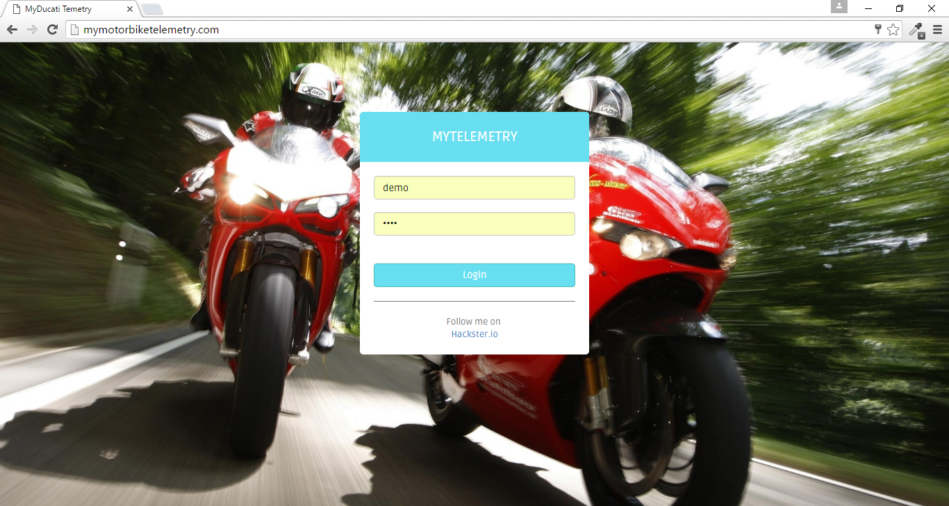
You can discover the web site by the following url:
Has been created an account for all Hackster Users , SignIn using the following user/psw credentials:
User ID:demoPassword:demo
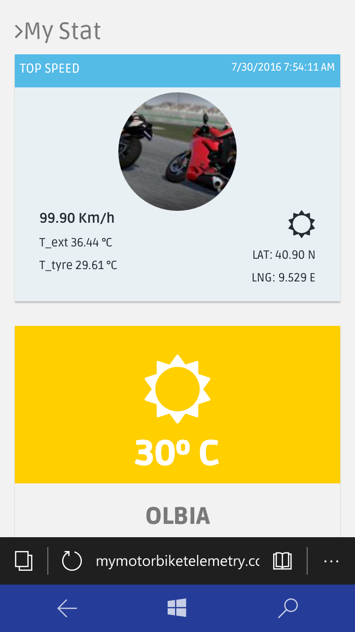
The web site is look like this:
And look like this in mobile version:

When you create a web app in azure using the Free tier, the domain name will be something like this:
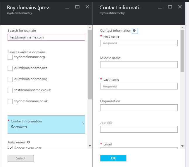
To change the domain name you have to buy one and on azure this is very simple! Follow this steps:
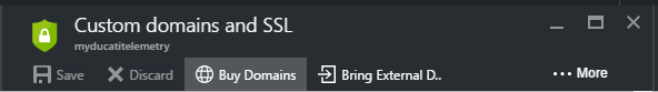
- Go to your Azure dashboard and click on you web app Tile.
- Select "Custom domains and SSL " and click on "Buy domains ".
- Fill all fields (about your domain name and your contact informations)
Ducati Monster Wiring
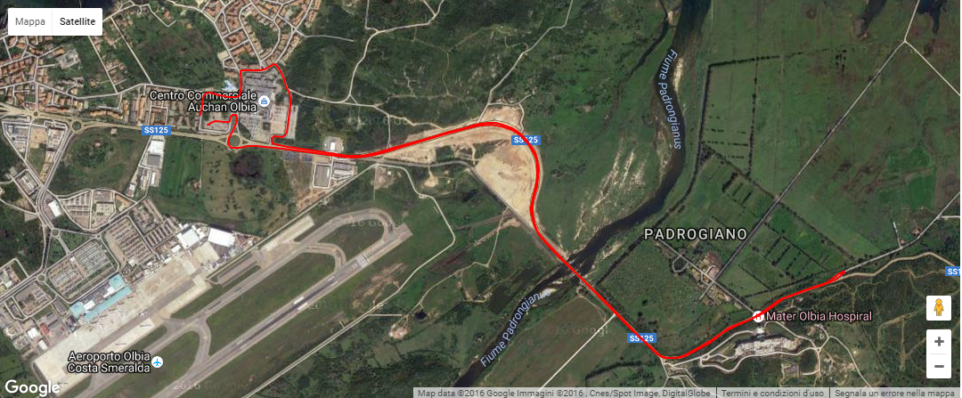
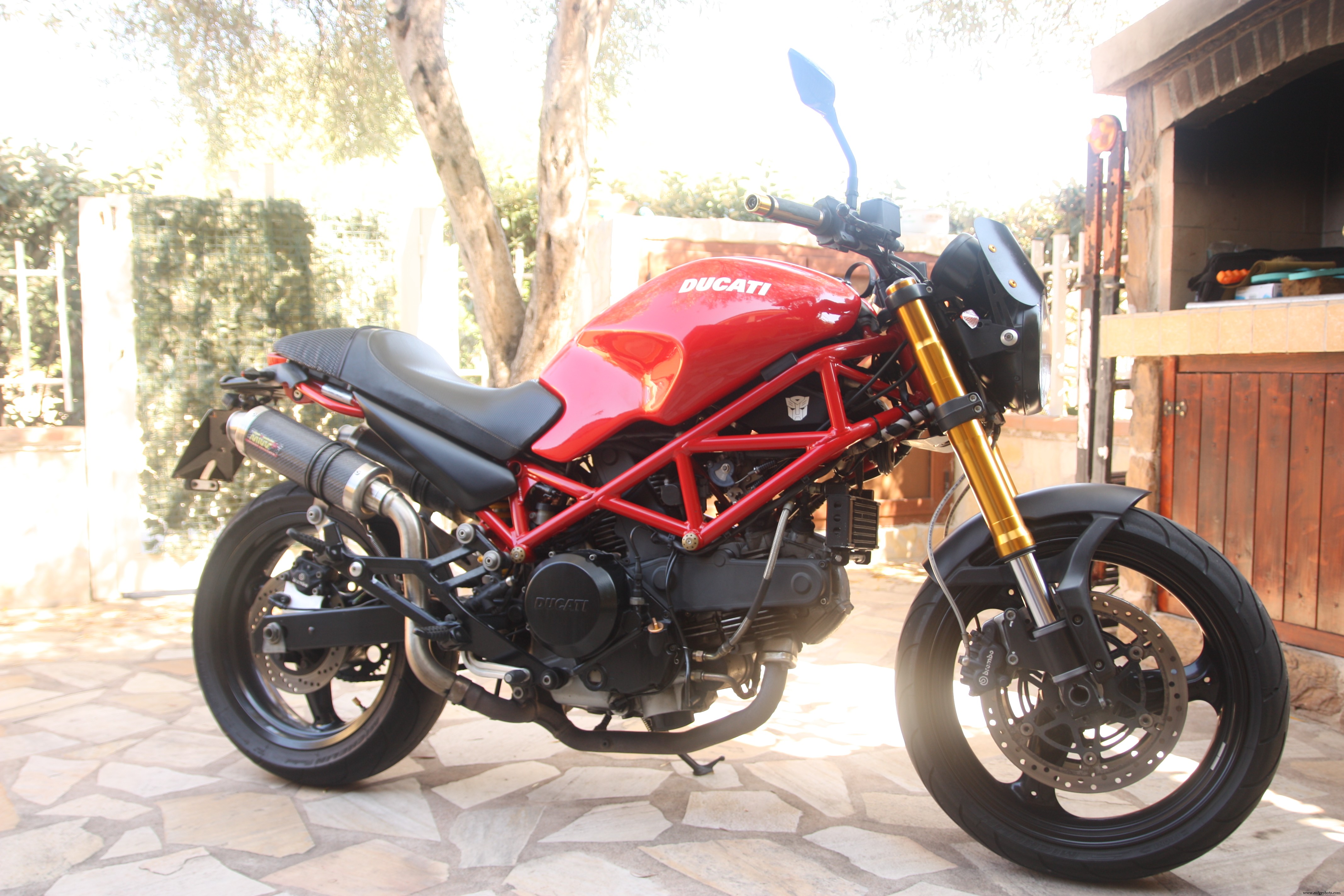
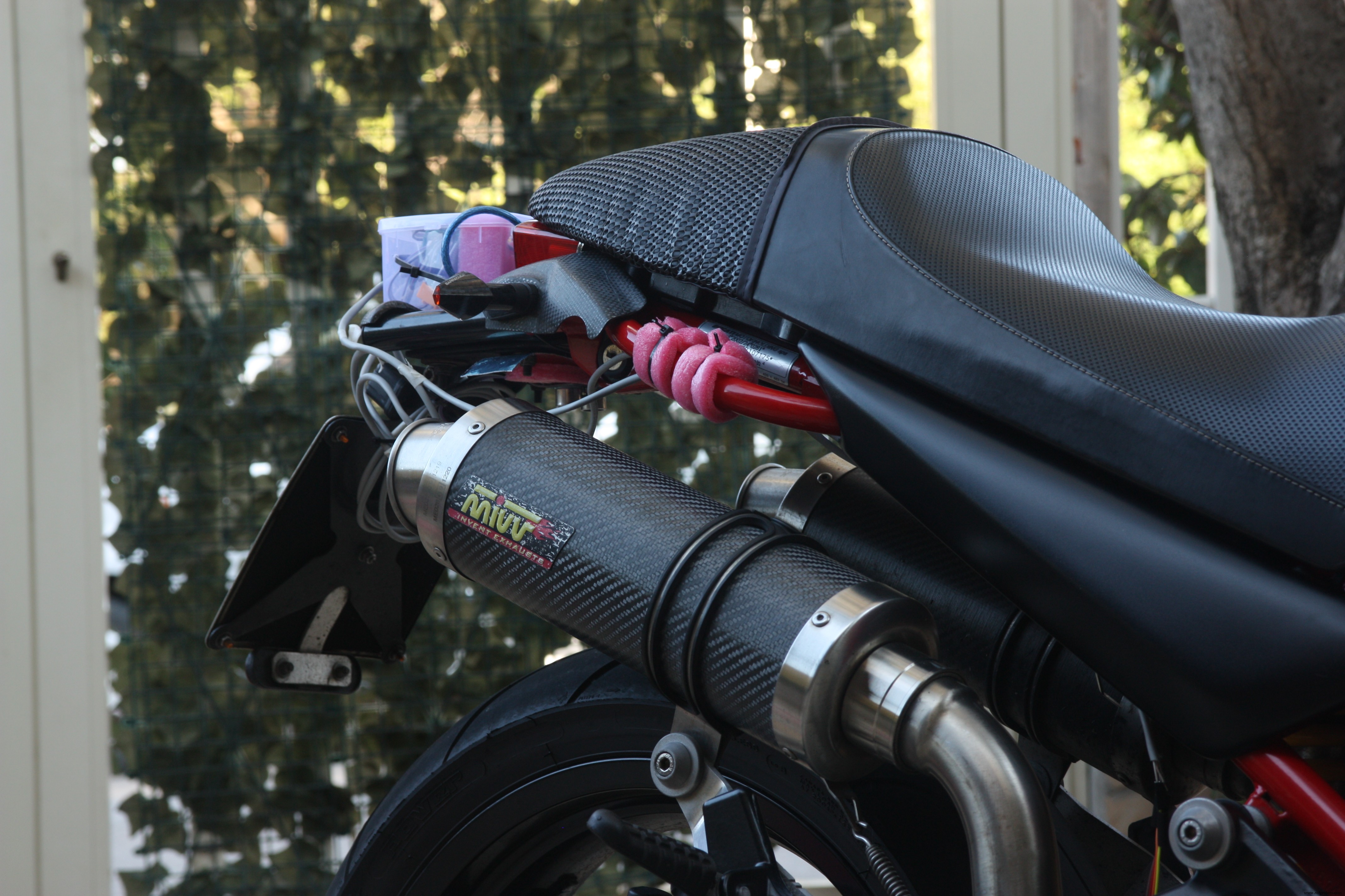
Now is time to Introduce my motorbike, this is my Ducati Monster 695 that for this project has been the cavy.
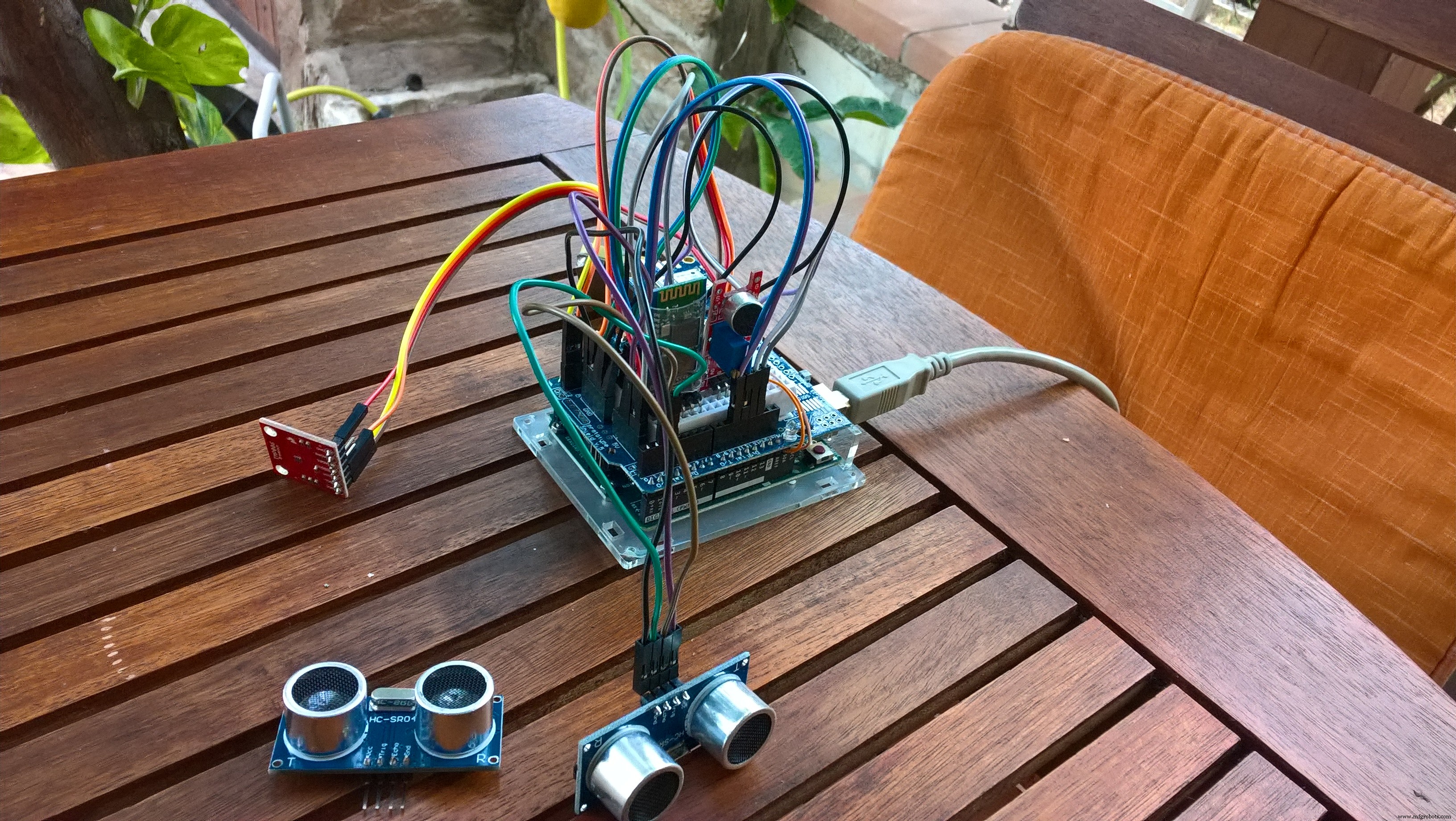
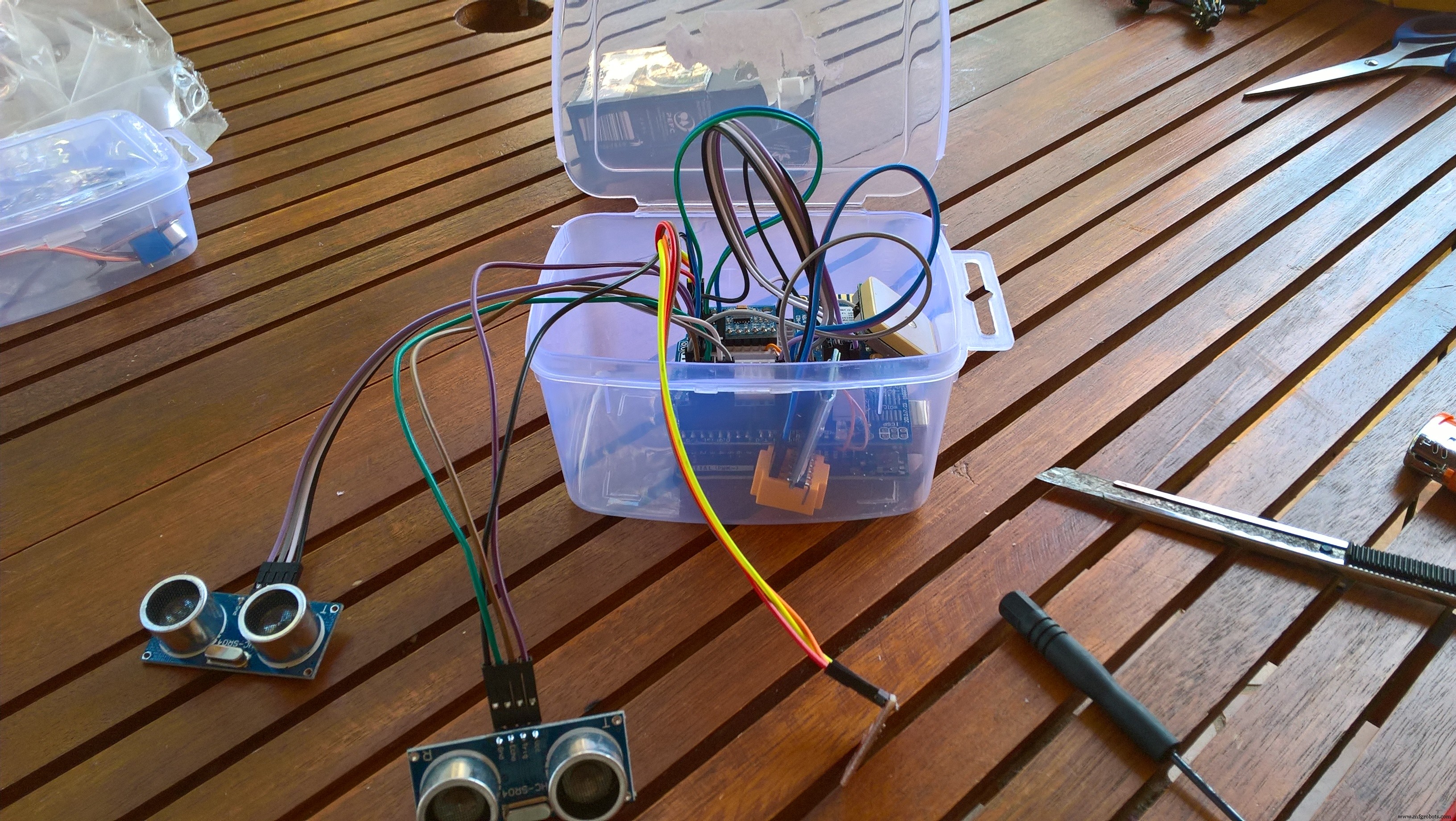
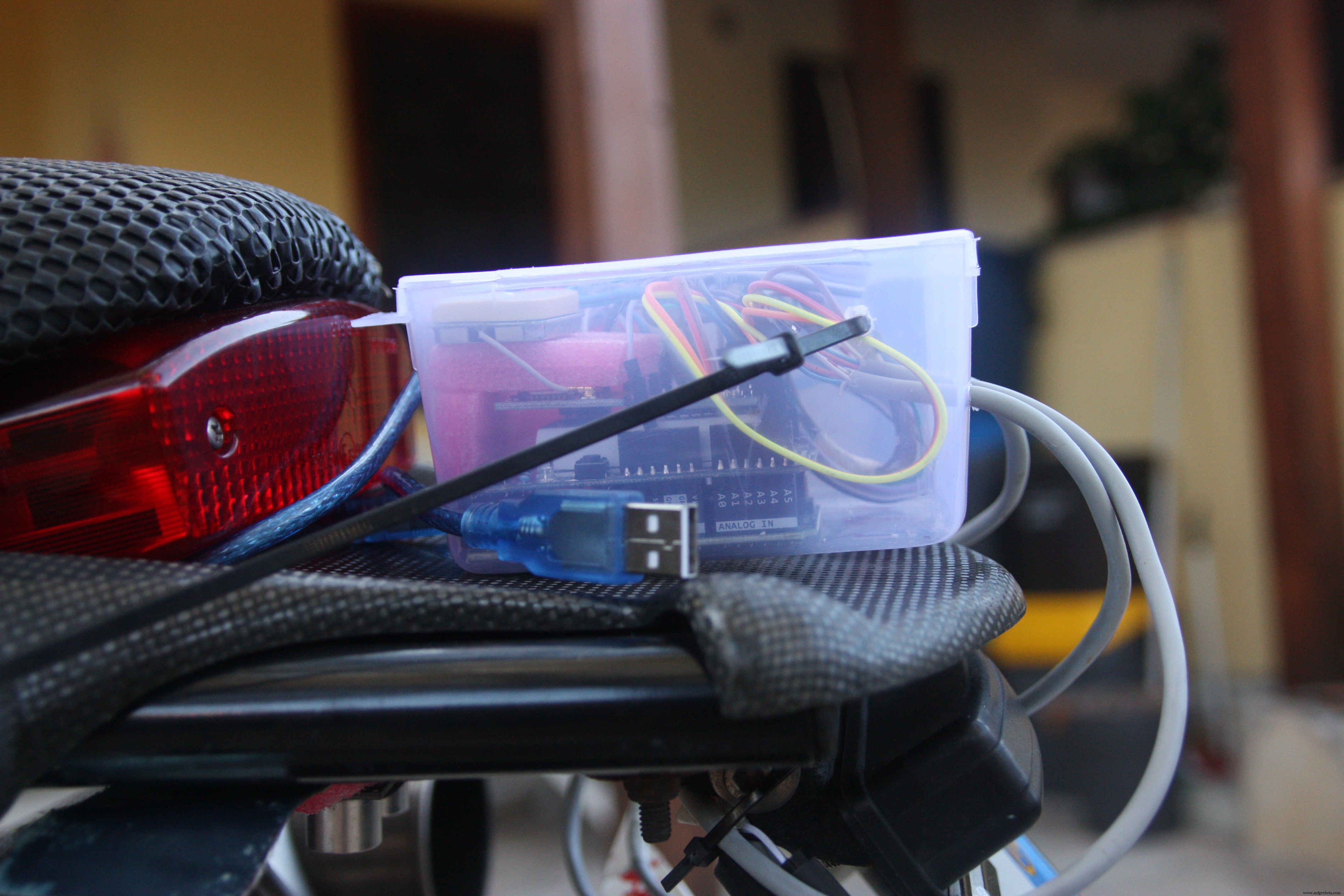
Below some pictures about my Hardware (control unit) mounted onboard.

to measure the tyre temperature I created a bracket clamped behind the wheel.
One Ultrasonic ranging module HC-SR04 has been fixed under the front headlight. It misures the distance between headlight and front mudguard.
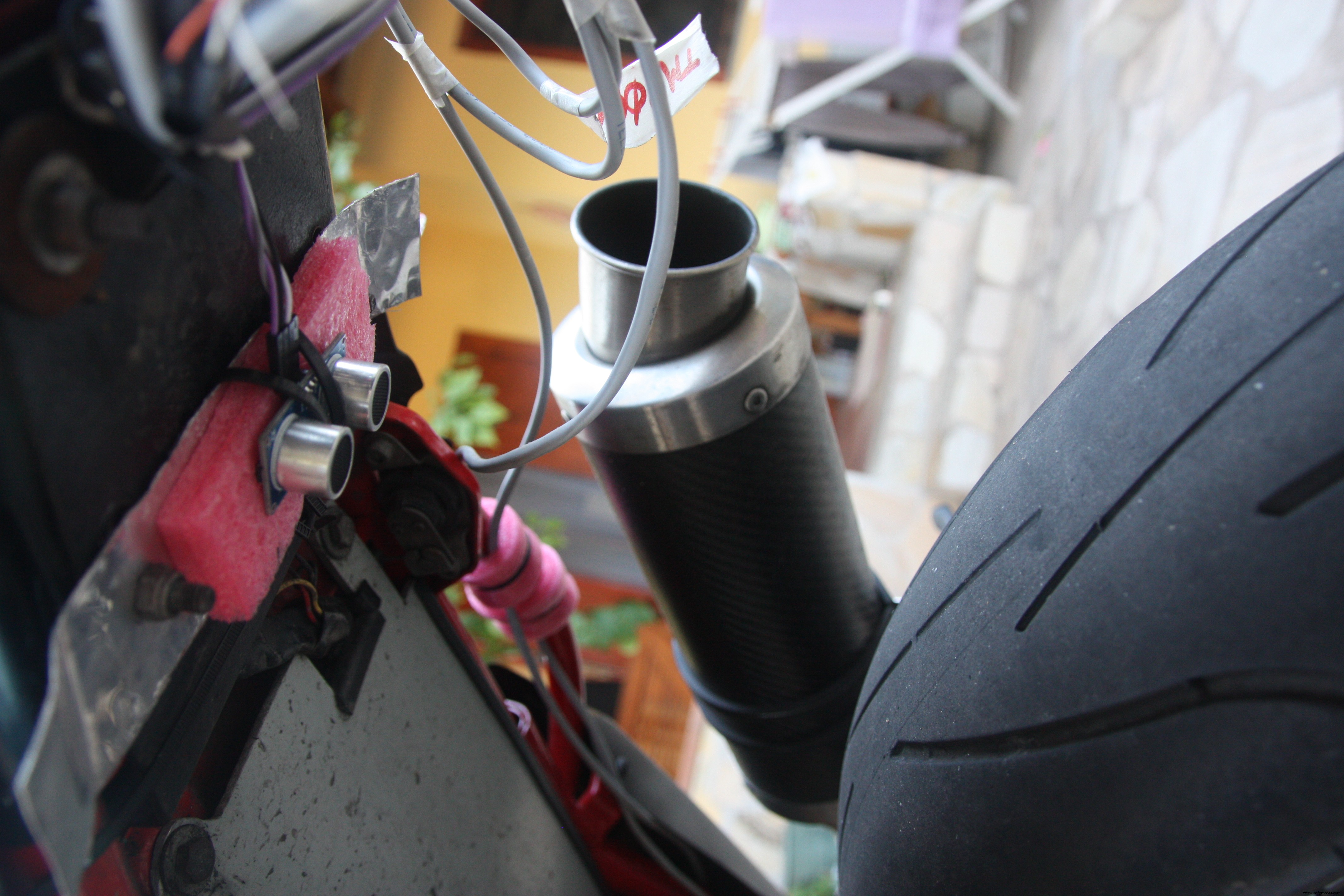
The other one Ultrasonic ranging module has been fixed under the bike seat in order to determined the back shock absorber measuring the distance between seat and rear tyre.
The central unit containing the Arduino, the GPS, the Accelerometer and the external temperature sensor has been fixed behind the seat.

And at the end, after the wiring, my motorbike is look like this

Machine Learning
The last idea of this project has been try to understand if exist a correlation between telemetries data in order to try to understand how to improve my driving style.
My data samples are not relatable because I make different routes every time and the traffic conditions are never the same. I think that a good condition should be use the system in a speedway. I Imagine that in a real race could be usefull to understand by telemetry if you can increase the speed or if you have to decrease the speed according to the output values.
The Machine Learning (ML) embodies the magic of software insights about the data, solves problems by giving information that represents a certain evolution. The ML understands how a given phenomenon will evolve according to the data in its knowledge.
The first approach using the ML is to do Experiments . Using the data, you can play and be able to do the analysis with the aim of investigating the phenomenon that interests us.
Ok let's go to discover the Azure Machine Learning
Go to https://studio.azureml.net and sign in using your Azure account.
On the left of the page click on "Studio"
You will be redirect to your personal Dashboard and now you will be ready to create experiments
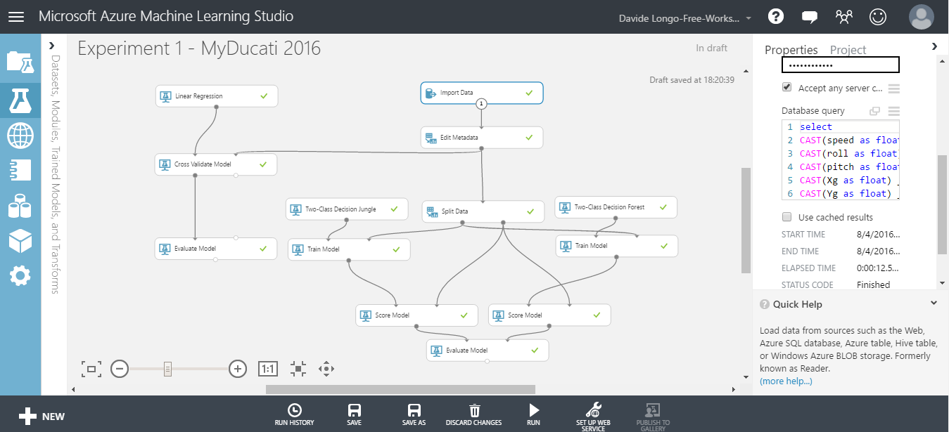
- In the experiments blade, Click NEW (on the left button of the page) .
- The first step is to Import data that you would like to use in your ML. In my case I imported the data from SQL Azure.
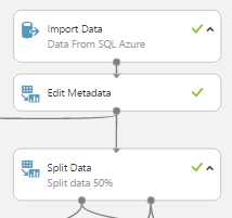
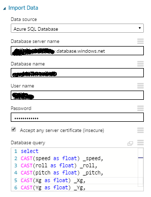
- Into my Table all data are varchar so i needed to convert it in float and excluding some bad data in order to have only best quality records. Below you can see the query used to import data
select CAST(speed as float) _speed, CAST(roll as float) _roll, CAST(pitch as float) _pitch, CAST(Xg as float) _Xg, CAST(Yg as float) _Yg, CAST(Zg as float) _Zg, CAST(TempExt as float) _TempExt, CAST(TempTyre as float) _TempTyre, CAST(FrontAbsorber as float) _FrontAbsorber, CAST(BackAbsorber as float) _BackAbsorberfrom mytelemetrywhere CAST(speed as float)>3 and CAST(FrontAbsorber as float)>0 and CAST(BackAbsorber as float)>0 and CAST(roll as float)<60 and CAST(roll as float)>-60
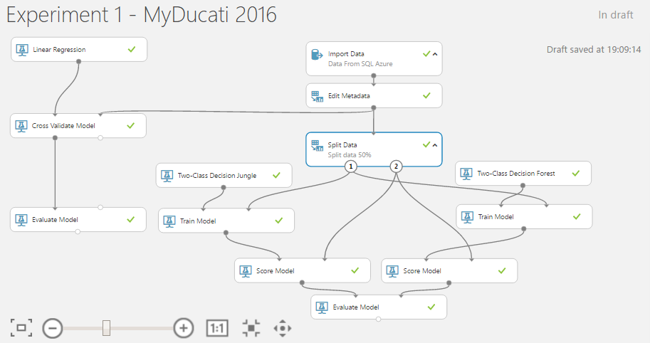
- Then add a SPLIT DATA element in order to use some data to Train your ML and decide the data percentage to use for the configuration.
- A data portion will be used to configure the template and the other portion to see if your model works fine. This will allow me to assess the goodness.
- Add a Train Model and decide what is the field that would you like the model guess and decide which algorithm use for your train.

- Now we verify how he behaved the algorithm giving us a feeling of goodness, to do that we need to use "Score Model ". the SM accept in input 2 sources, the first one is from Train Model and the second one from the SPLIT DATA .
- At the end we ready to estimate the model according to the test data, comparing them with those that have not yet used (Evaluate Model ).
Official Documentation about " Evaluate Model" can be found here
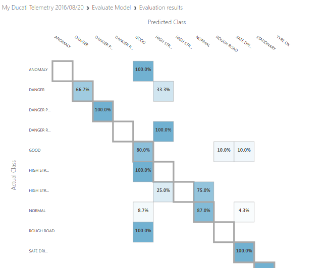
Below there is a sample experiment useful for comparing 2 algorithms using the Evaluation Model , the 2 algorithms are Two-class decision jungle and Two-class decision forest .
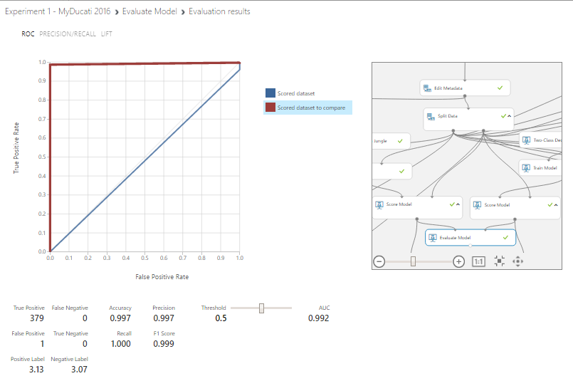
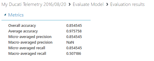
When you pass on a scored model for a "two classes" classification algorithm, the evaluation model generates metrics shown below:
Classification Models
The above metrics are reported for evaluating classification models.
(All metrics are reported but the models are ranked by the metric you select for evaluation)
- Accuracy measures the goodness of a classification model as the proportion of true results to total cases. Accuracy =(TP + TN) / (TP + TN + FP + FN)
- Precision is the proportion of true results over all positive results. Precision =TP / (TP + FP)
- Recall is the fraction of all correct results returned by the model. Recall =TP / (TP + TN)
- F-score is computed as the weighted average of precision and recall between 0 and 1, where the ideal F-score value is 1. F1 =2TP / (2TP + FP + FN)
- AUC measures the area under the curve plotted with true positives on the y axis and false positives on the x axis. This metric is useful because it provides a single number that lets you compare models of different types.
As you can see, the Two-class decision forest Algorithm have an Accuracy , Precision ,Recall and F1 Score near the value equal to 1, so i suppose that my model is good described, GREAT !!!
For more details about Evaluate Model please visit the following LINK
Predictive Experiment:
It's time to move our attention on the predictive functionality of the machine learning.
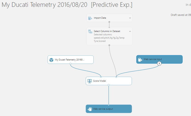
The Training experiment will be convert to a predictive experiment, this feature allows to integrate in others applications the opportunity to use your model and based on your model have a Prediction.
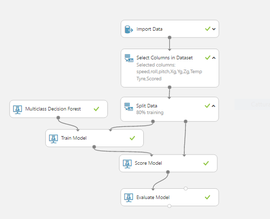
For do that, has been created a new one Experiment, the data source has been the SQL Azure but this time the table used has been a new one. I tried to classify data based on telemetry values.
Now my data look like this and as you can see there is a new column named Scored that represents my classification:

Create the experiment like below, select the Train Model and add a Multiclass algorithm:
- RUN the experiment and see the results:
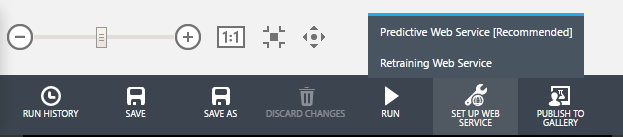
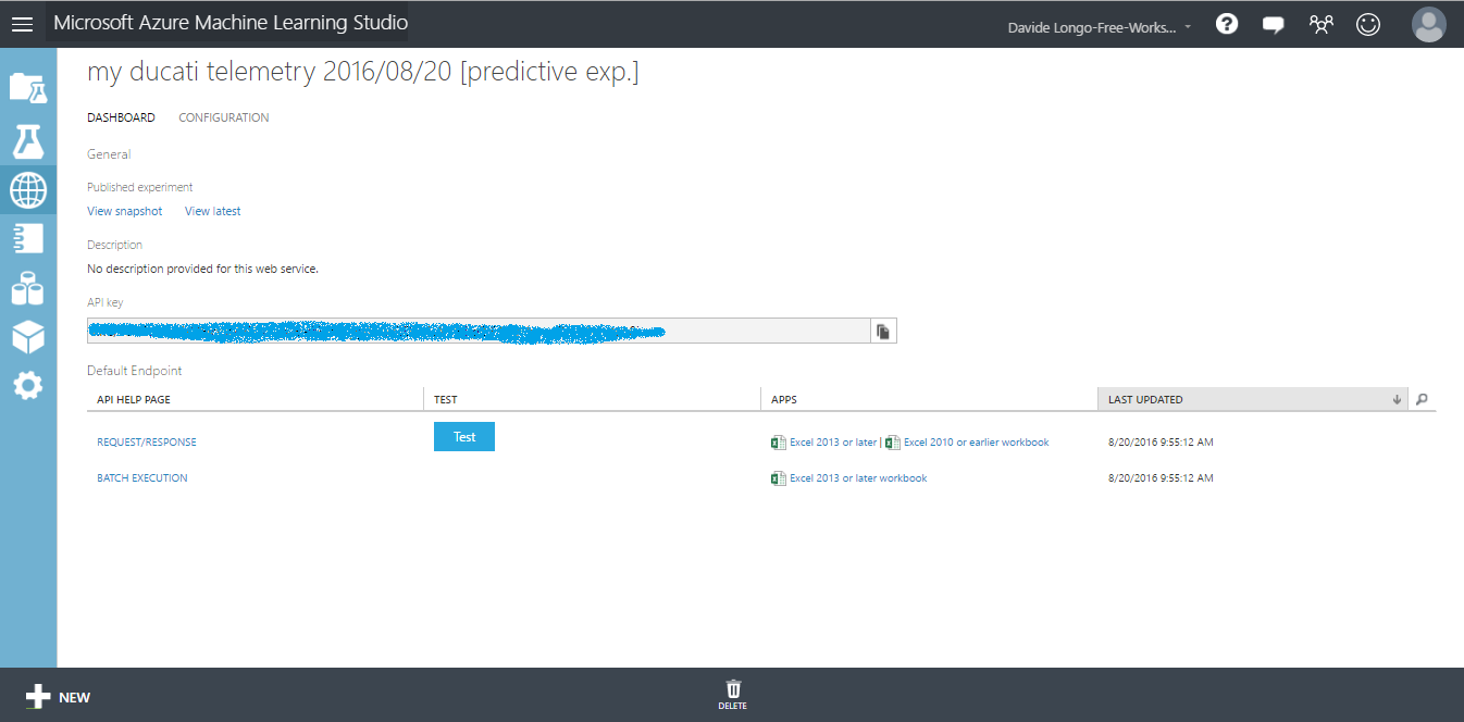
- Select the Train Model and click on SET UP WEB SERVICE => Predictive Web Service
- Wait some seconds and your predictive service will be ready. Below you can see my Predictive Experiment layout:
- Run this model and then deploy the web service by clicking on the DEPLOY WEB SERVICE button

- Your service will be immediately ready to be used and a dashboard will appear, contain a "TEST" button where you can manually enter data and test your service
- Click TEST button and compile all fields, use some fake values and see the Predictive result:
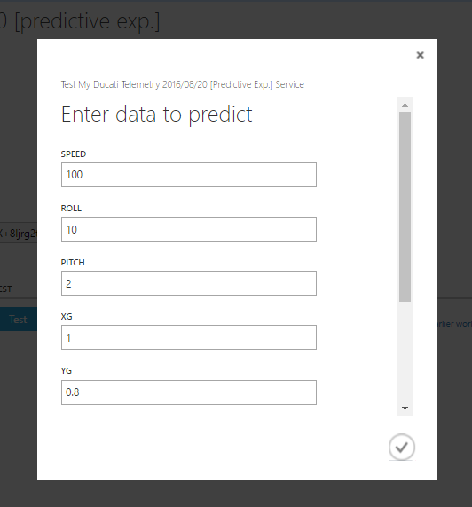

As you can see the result is equal to "SAFE DRIVING ", this mean that my Predictive service has predicted that my driving style is Safe and no action is needed.
If the Result has been for example "HIGH STRESS HIGH SPEED " that means that I have to reduce speed!
Conclusions about ML:
in this section we understand some things.
- How configure an experiment in ML azure environment
- we found that Two-class decision forest Algorithm well describe my motor bike telemetry and we train the ML for the predictive experiment using the Multiclass decision forest Algorithm
- How to convert our Model in a Web Service creating a predictive experiment
- we found some usefull information about my style of guide. Infact as you can see from the below graphs:
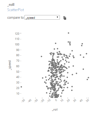
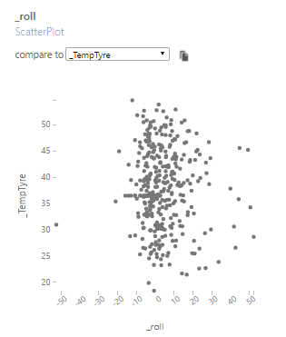
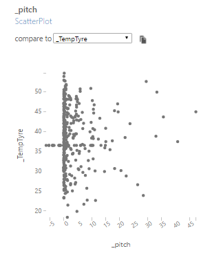
I prefer lean on the right and my lean angle doesn't depend for tyre temperature and from the speed. That mean that my tyres are high quality and in add I undestood that my motorbike prefers Wheelie when the tyre temperature is more than 35°C
Final Conclusions
In this project we covered many technological areas.
We discovered How is possible to create a funny Hardware using an Arduino and some sensor spending less then 60$ and using many services provided by microsoft.
We learned how is easy use Azure and how is interesting use Machine Learning Studio suite.
Has been realized a prototype that certainly needs improvements but i think is a good starting point for future developments from each people enthusiast about C#, Azure, Arduino and MotorBike.
Possible future Developments
To Improve this prototype i think will be usefull implements some things:
- About the mobile app (UWP), in case that no 3G/4G network is available, the data are lost because i'm not able to send the data to azure. Would be usefull develop a buffering logic that in case of "no networking" available, stored the data and send them at a later time.
- Create an APP for mobile platform using Xamarin, would be cool have an app who can run in Android OS and iOS also.
- Use more precise sensors and increase performance/accuracy.
- Make the central unit smaller, maybe using an Arduino MKR1000 .
- Create a social media Webapp to share your motorbike travel and telemetries in order to suggest to biker users what is the dangerous curves and increase the safety.
- Modify the source of the Machine Learning using the Steam Analytics. In my case i prefered use a sql AZURE datasource because it was not possible ride the bike and develop the ML in the same time :)
New branch work flow:
- The new branch consists to sending back to device, through IoTHub , the information about the ML predictive service.
- When the speed value is greater than 100 km/h a new one stream analyticsJob will send the telemetry data to Event Hub.
- A cloud service reads this data from EventHub and send a request to the ML predictive service in order to have a score about the Driving Style .
- The Cloud Service will send back the score to IoTHub , and IoTHub will send it to the device back (Windows Phone in this case)
... and now ENJOY !! :-) feel free to contact me for any questions and tips.
Código
UWP App C# Code
https://github.com/lentzlive/MotorbikeArduinoARDUINO CODE - Bike Telemetry
https://github.com/lentzlive/BikeTelemetryArduinoEsquemas
circuit diagrams of the Telemetry system. On board scheda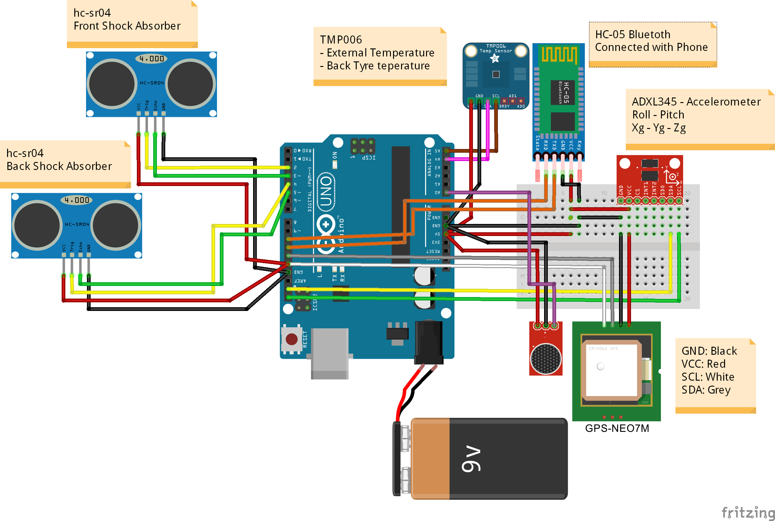 MotorbikeProject.fzz
Processo de manufatura
- Telemetria do Sensor 2.0.1
- Evitar Obstáculos usando Inteligência Artificial
- Diversão do giroscópio com anel NeoPixel
- Controlador de jogo Arduino
- Traje da nuvem
- Seguidor de linha industrial para fornecimento de materiais
- Pixie:Um relógio de pulso NeoPixel baseado em Arduino
- Garrafa de água alimentada por Arduino
- Teatro Holiday Shadow
- Câmera de vigilância remota móvel