


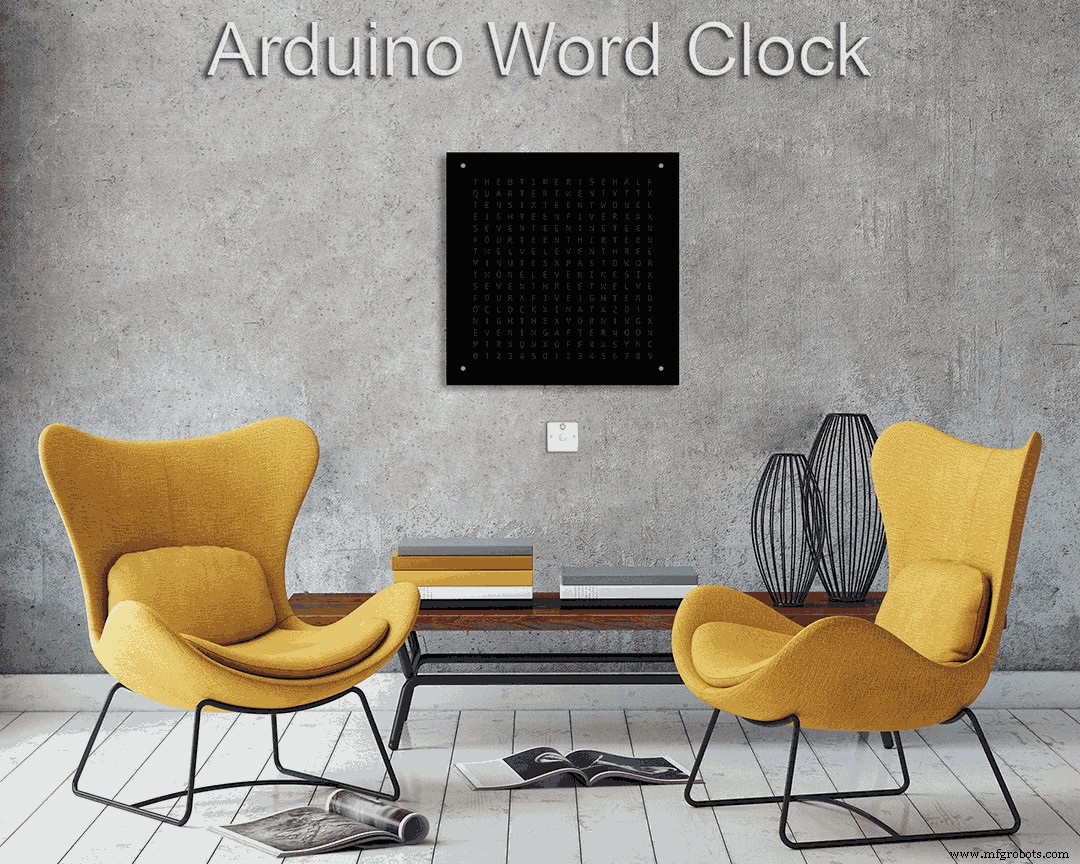
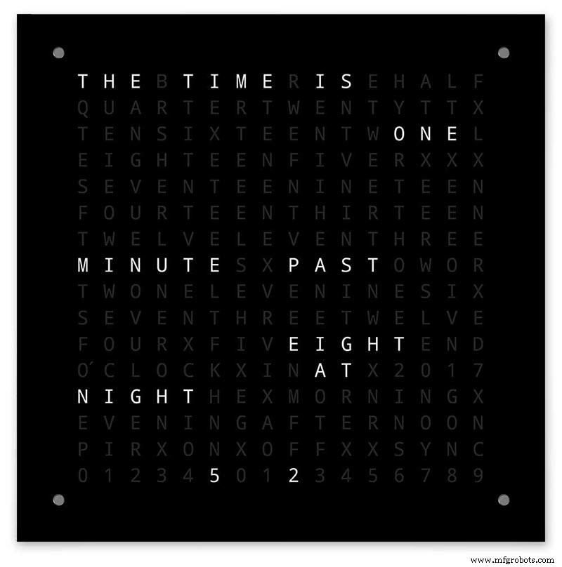
Word Clock com resolução de minutos em palavras
Componentes e suprimentos
 |
| × | 1 |
Sobre este projeto
Mais detalhes sobre esta construção podem ser encontrados em meu site aqui:Word Clock
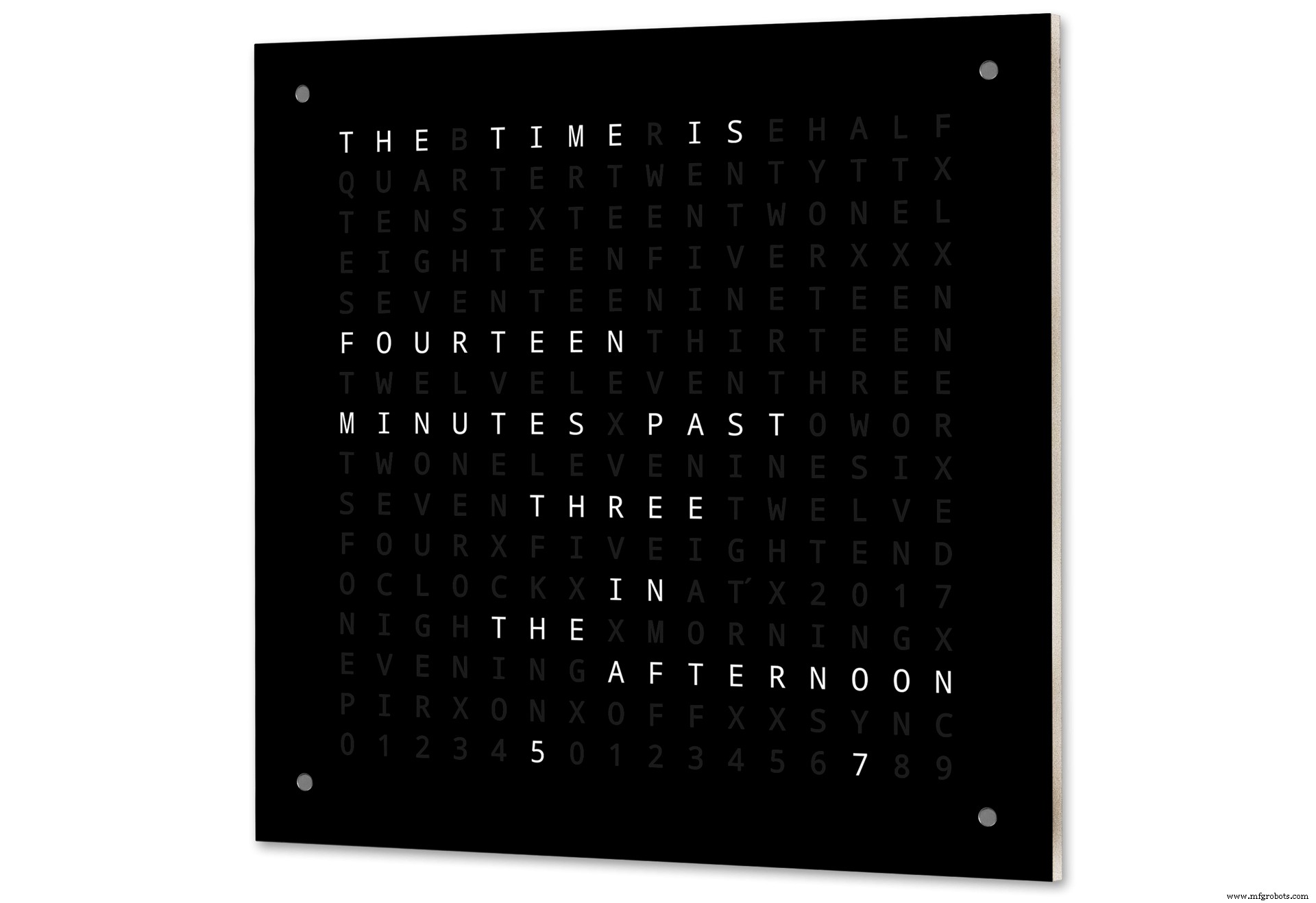
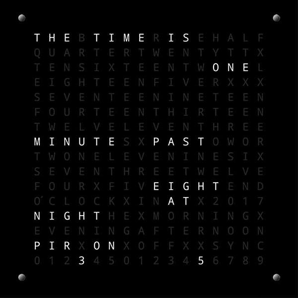
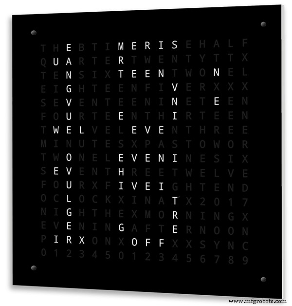
O Word Clock Arduino com resolução de minutos de tempo em palavras e exibição linear de segundos.
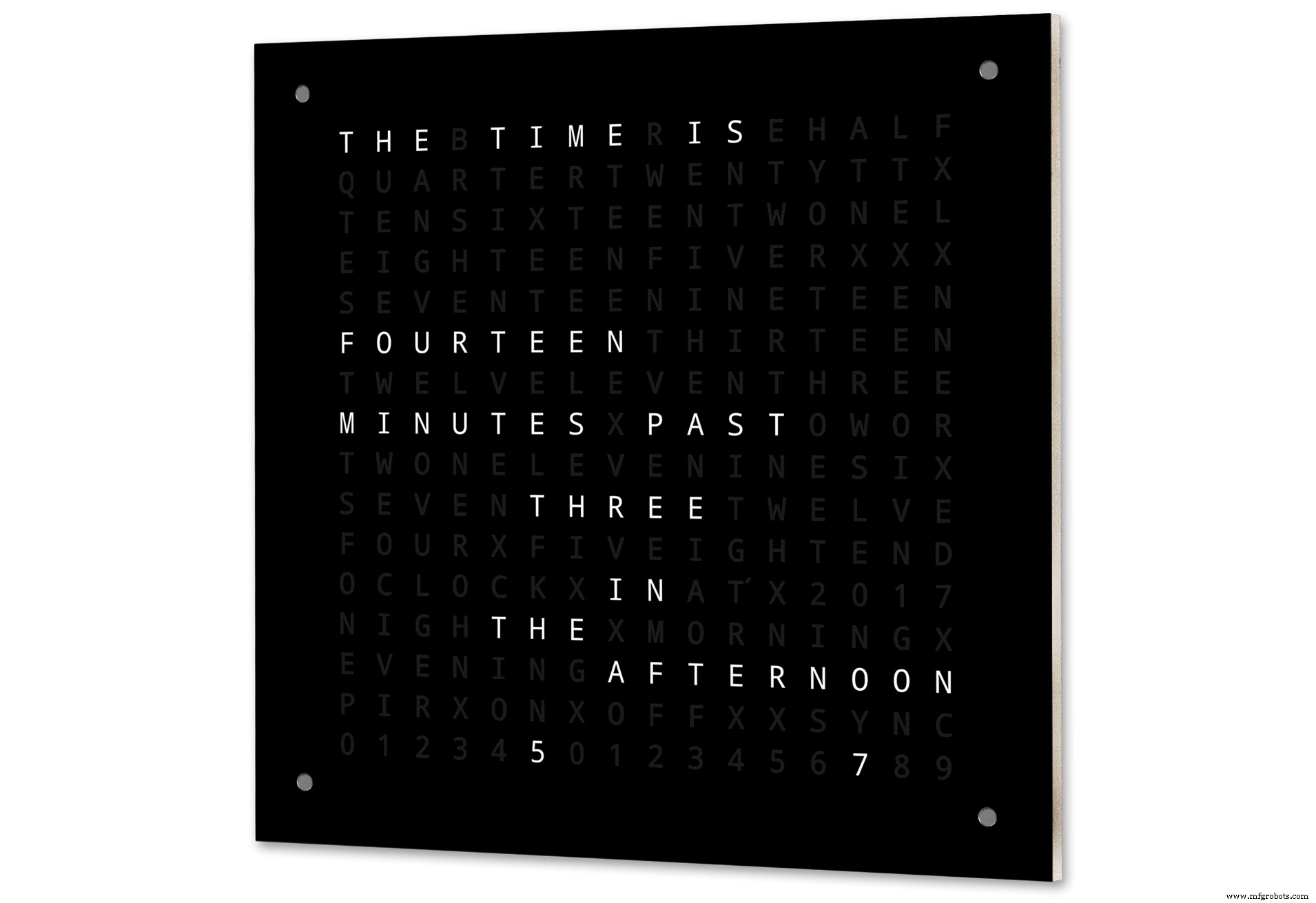
Existem também modos para relógio digital, relógio analógico, temperatura e umidade, além de três jogos:Game of Life, Simon e Tetris.
O relógio pode ser autônomo ou funcionar como um escravo de um relógio mestre, se necessário.
Sem um relógio principal, o tempo é controlado pelo relógio de cime real com compensação de temperatura embutido do word clock.
Há uma opção para controle de radar PIR ou Doppler para que o relógio desligue automaticamente quando não houver ninguém na sala.
O relógio mede 500 mm x 500 mm (19,68 "x 19,68"), pesa 5,5 kg (12 lb) e foi projetado para ser montado na parede. Existem touch pads em cada canto para configurar e controlar o relógio.
Etapa 1:Sobre Word Clocks
Sobre Word Clocks
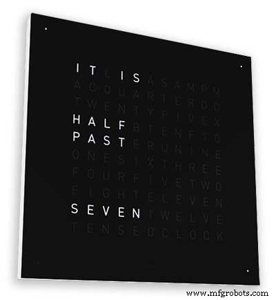
Relógios de palavras marcam as horas usando uma matriz de palavras ou números e letras e existem há muitos anos. Existem alguns tipos de design diferentes que afetam a complexidade da construção do relógio.
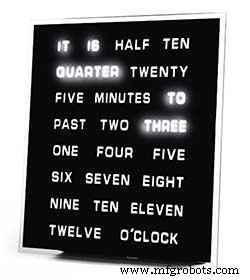
Os mais simples usam blocos de palavras para dizer a hora em resolução de cinco minutos, por exemplo, O'CLOCK, 5 PAST, 10 PAST, etc. Esses relógios usam apenas 20 ou mais blocos de LED individuais e, portanto, são os mais simples de construir. A principal desvantagem desses relógios é que eles só podem mostrar a hora neste formato definido.
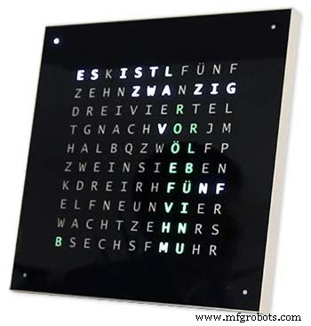
O relógio de nível médio tem uma matriz de 11x10 LEDs mais quatro LEDs adicionais ao redor do relógio. O relógio controlado pelo Raspberry Pi Photo 2 tem até LEDs multicoloridos e como tem 110 LEDs individuais pode exibir dígitos e imagens básicas. Esses relógios ainda usam uma resolução de 5 minutos em palavras, mas geralmente adicionam "acabou de 5 anos" ou quase 10 a "para aumentar um pouco a resolução. Freqüentemente, os quatro LEDs nos cantos do quadro indicam a passagem de quatro minutos para preencher a lacuna entre a resolução redigida de 5 minutos. Esses relógios são razoavelmente complexos de construir e costumam usar tiras de LEDs para tornar a construção mais fácil.
Existem versões comerciais deste tipo de relógio disponíveis. A versão de 450 mm para pendurar na parede custa cerca de £ 1000 e apresenta painéis frontais intercambiáveis em várias cores e materiais, bem como desktops e relógios menores.
256 matrix Word Clock por Wouter Devinck
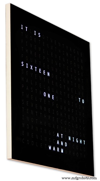
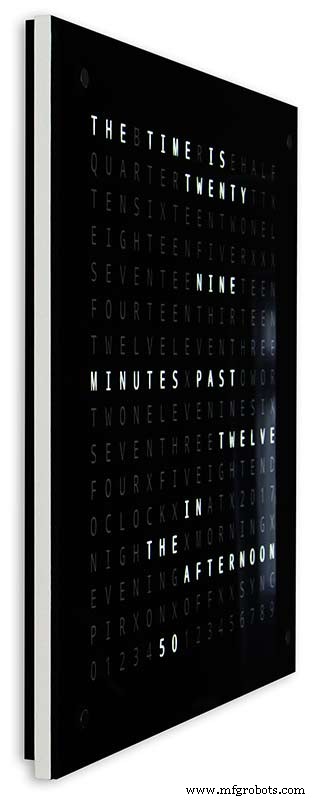
Os wordclocks com o mais alto nível de complexidade usam uma matriz de LED de 16x16, fornecendo 256 LEDs para controlar. Esses relógios têm uma resolução de tempo de um minuto, bem como de manhã, tarde, noite, etc. Eles costumam dizer a temperatura aproximada em palavras como quente, muito quente, frio muito frio etc.
Com os 256 LEDs para brincar, há uma grande quantidade de modos de exibição diferentes disponíveis. Esses relógios são bastante complexos de construir devido ao número de conexões no display de matriz. Construir a matriz de LED em PCBs com componentes de montagem em superfície permite corpos de relógio muito finos e torna a construção da tela mais simples, mas acima de 500 mm x 500 mm os PCBs começam a ficar caros.
Construir manualmente a matriz de LED, pois meu relógio precisa de espaço e 500 mm x 500 mm é um bom ponto de partida, pois pode acomodar os grandes teares de fiação necessários para interconectar os LEDs e os módulos de exibição. Relógios de enchimento de parede muito grandes podem ser construídos usando matrizes LED feitas à mão.
Etapa 2:alterações
Alterar
Este relógio é uma mistura do hardware Wouter Devinck Clock e do software de relógio Pijuana "catalão". Eu não usei nenhuma placa de circuito impresso, apenas módulos prontos e três pequenos circuitos da placa Vero para a alimentação.
As principais mudanças são detalhadas a seguir.
Nenhum PCB personalizado é usado nesta versão do relógio, apenas barato e fácil de encontrar por módulos pré-construídos.
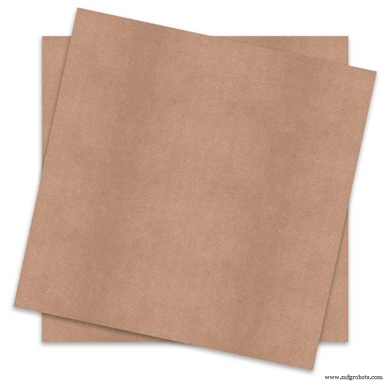
O corpo do relógio principal é construído com 2 x folhas de MDF de 14 mm em vez de uma única folha de 18 mm.
A folha posterior é 10 mm menor do que a folha frontal em todos os lados, exceto na parte superior, de modo que o relógio parece ter apenas 14 mm de espessura.
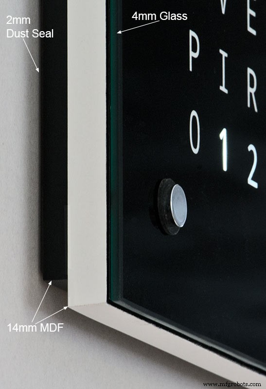
O relógio Wouter Devinck tem apenas 20 mm de profundidade, incluindo o vidro de 2 mm, enquanto meu relógio tem 34 mm de profundidade, incluindo o vidro de 4 mm e a vedação contra poeira de 2 mm na parte traseira. Devido ao recuo do painel traseiro de 14 mm e ao recuo de 1,5 mm do painel de vidro da maioria dos ângulos, o relógio parece ter apenas 14 mm de profundidade. Essa profundidade extra me permitiu usar uma matriz de LED feita à mão e teares de fiação em vez de 4 grandes PCBs. Isso também significa que posso usar módulos pré-construídos de fácil manutenção sem ICs de montagem em superfície nas placas MAX7219.
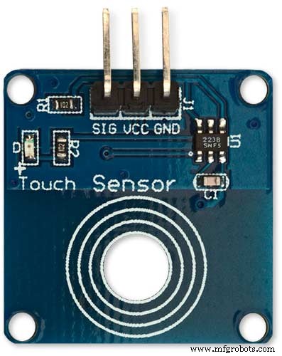
O display principal é construído diretamente para os LEDs do display sem PCB, portanto, qualquer tamanho de display é possível. Módulos de sensor de toque TTP223 são usados em vez do Azoteq IQS127D montado nas placas principais.
As placas de driver de vídeo para o MAX7219 I / C usam placas de matriz de LED modificadas. Essas placas vêm completas com todos os componentes.
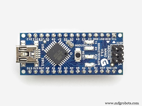
Um Arduino Nano é usado para acionar o relógio devido ao seu tamanho pequeno.
Um módulo sensor PIR é usado para desligar o display quando não há ninguém na sala (isso pode ser desabilitado para manter o display sempre ligado).
Um resistor trimmer é adicionado ao circuito, acessível pela parte inferior do relógio com uma pequena chave de fenda para calibrar o brilho automático da tela.
Sincronização com meu sistema de relógio mestre a cada minuto em 30 segundos. Se nenhum pulso de sincronização estiver disponível, o relógio será executado livremente usando o RTC. Os pulsos de sincronização são exibidos na tela principal.
O software baseia-se principalmente na versão "catalã" Pijuana do word clock, por isso foi traduzido para o inglês para exibição. Exibição de créditos modificada da versão "catalã" Pijuana "para mostrar o número da versão atual do software, meu nome e também o ano de construção.
A temperatura expressa foi removida da exibição do relógio e uma exibição de segundos lineares adicionada à linha inferior dos relógios Word, Digital e Analógico.
Quando o PIR é ativado ou desativado, "PIR ON" ou "PIR OFF" é exibido por alguns segundos no visor de wordclock.
Este relógio usa um módulo de relógio de tempo real de precisão DS3231 AT24C32 I2C de acordo com o relógio Wouter Devinck e o relógio Pijuana "Catalão". Não gosto de usar a bateria recarregável de íon de lítio fornecida com o módulo. Eu uso uma bateria não recarregável e modifiquei o módulo para se adequar.
O vidro float de 4 mm com bordas polidas substitui o vidro de 2 mm. O vidro é fixado à placa principal de MDF usando Chicago Fasteners em vez de cola. Eles também atuam como touch pads para controlar o relógio e permitem que o vidro possa ser removido, se necessário.
Dois selos de poeira são integrados ao relógio, um no painel traseiro e outro atrás do painel de exibição de vidro removível. No modo de ajuste do relógio, pressionar o botão BOT para a direita agora redefine os segundos para 0.
As seguintes alterações no texto em inglês foram feitas para tornar o texto como eu o diria. A maneira como as pessoas falam sobre o tempo varia de região para região, dependendo de onde você mora / estudou, etc., etc. Não existe uma maneira correta, apenas a que soa melhor para você.
Removidas as palavras que indicam a temperatura no word clock. Eles foram substituídos por status de sincronização, PIR ON / OFF e exibição linear de segundos.
Mudou "MINUTES" para "MINUTE" no minuto passado e 1 minuto na hora.
Adicionado um "A" antes do "QUARTER" passado e "QUARTER" à hora.
Adicionado o "ONZE" ausente do relógio Wouter Devinck de acordo com suas notas.
Ao meio-dia, mudei a hora para ler DOZE HORAS DA TARDE.
À meia-noite, mudou a hora para DOZE HORAS DA NOITE. Depois da meia-noite, o relógio sempre mostrará NA MANHÃ.
O "O'CLOCK" agora não está pontuado e mostra apenas OCLOCK.
Etapa 3:Design da caixa
Como meu relógio não usa PCBs Display Matrix personalizados com componentes de montagem em superfície, minha caixa do relógio tem que ser um pouco mais profunda do que o design de Wouter.
Minha caixa tem 34 mm de profundidade e inclui a vedação contra poeira traseira de 2 mm, placa de MDF traseira de 14 mm, placa de exibição frontal de 14 mm e vidro float de 4 mm.
A caixa certa de Wouter tem apenas 21 mm de profundidade, painel único de MDF de 18 mm e vidro float de 2 mm.
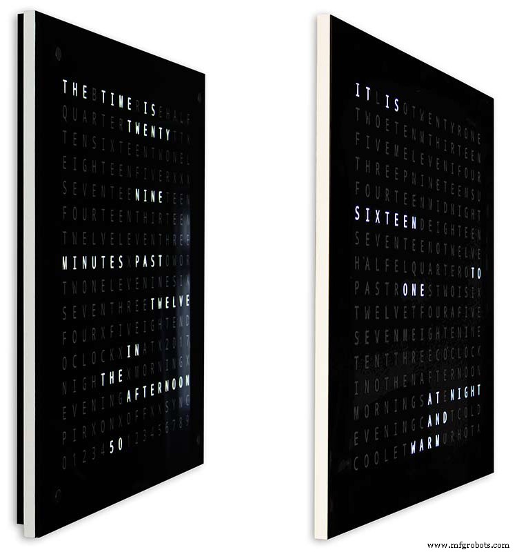
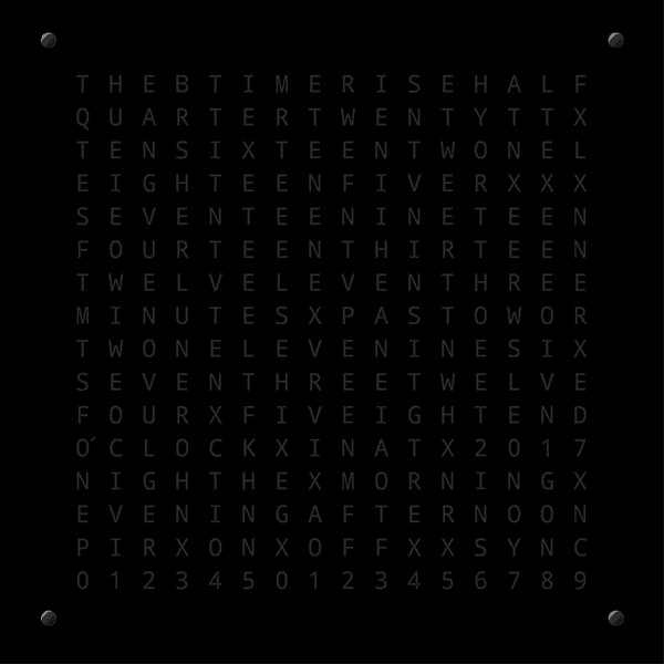
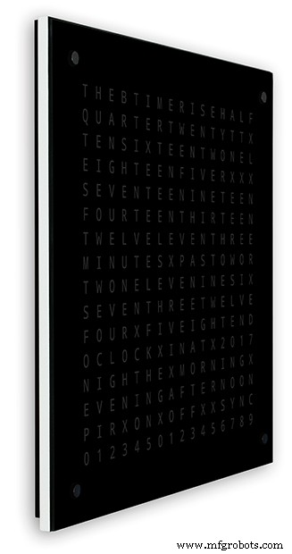
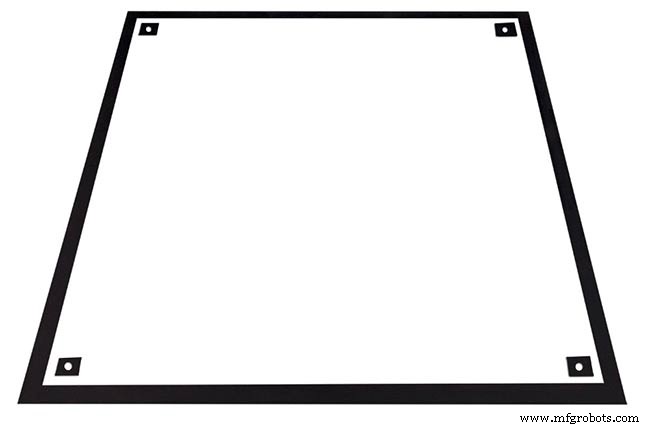
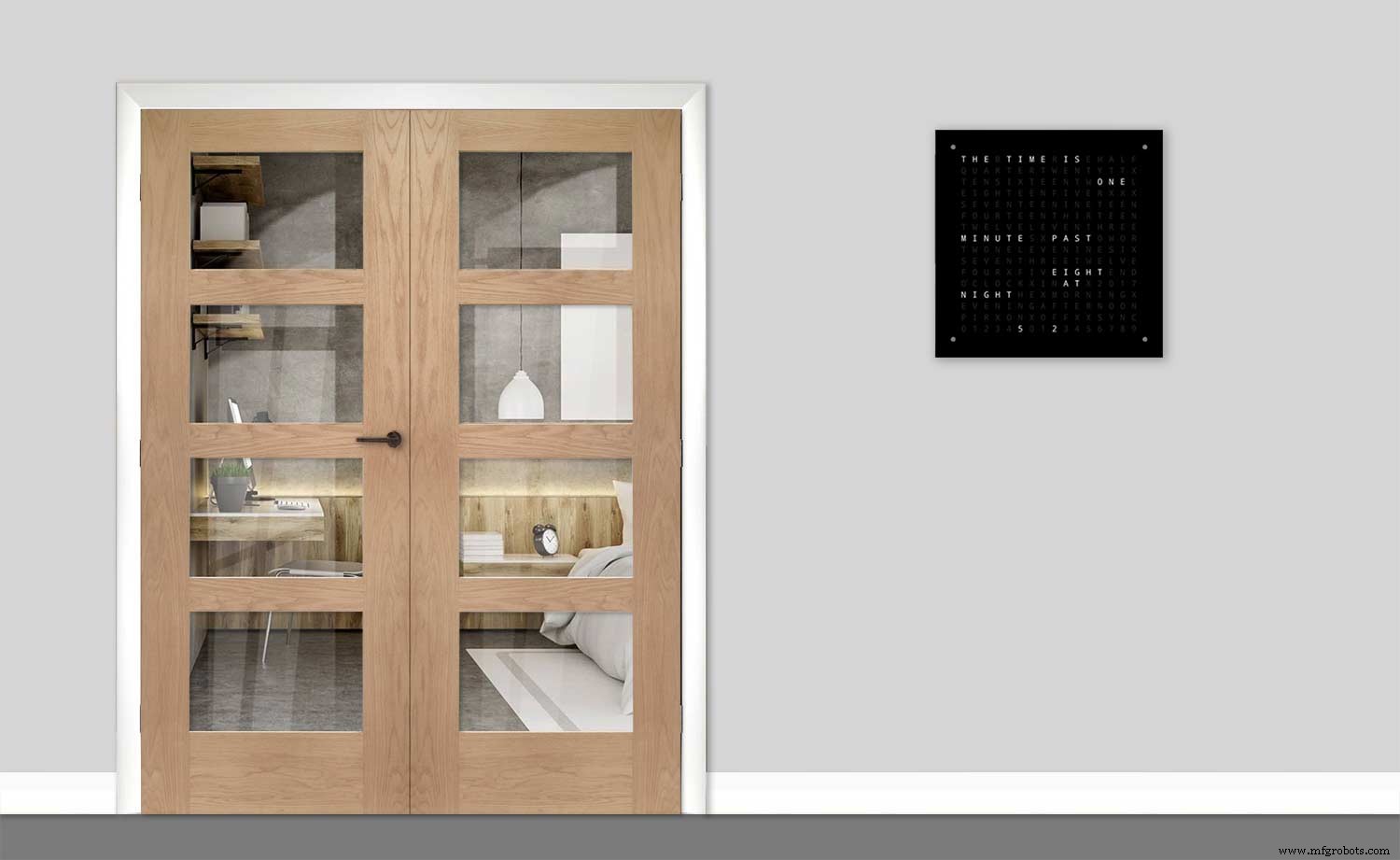
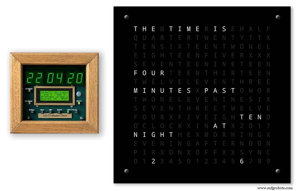
Para fazer meu relógio parecer menos volumoso quando montado na parede, incorporei alguns recursos de design simples. A foto acima mostra meu relógio à esquerda e o relógio de Wouter à direita. De um ângulo lateral extremo, você pode ver claramente que meu case parece mais volumoso.
Isso é compensado pelo painel traseiro ser preto em vez de branco, fazendo com que seus olhos se concentrem na borda branca fina de 14 mm. A placa traseira sendo 10 mm mais curta na parte inferior e em ambos os lados reforça essa ilusão.
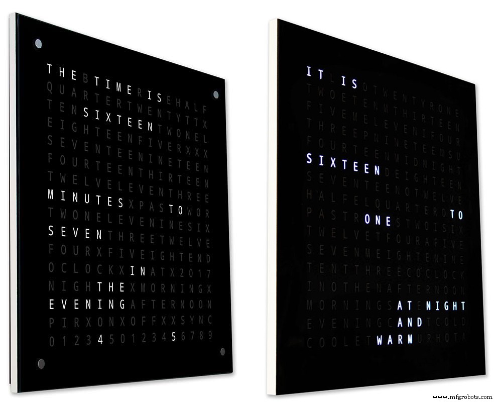
Acima - novamente meu relógio à esquerda e o relógio de Wouter à direita. Quanto mais para a frente dos relógios você vai, a placa traseira mais curta do meu relógio desaparece de vista até que apenas o painel frontal fino de 14 mm seja visível. O vidro de 4 mm também é cortado 1-2 mm mais curto do que o painel frontal, ajudando a ocultá-lo da vista . Minha caixa com relógio de 34 mm volumosa agora parece ser tão fina quanto a caixa de Wouter.
Etapa 4:controles
Controles

Existem módulos de controle de toque TTP223 no relógio, cantos superior esquerdo, superior direito, inferior esquerdo e inferior direito da tela.
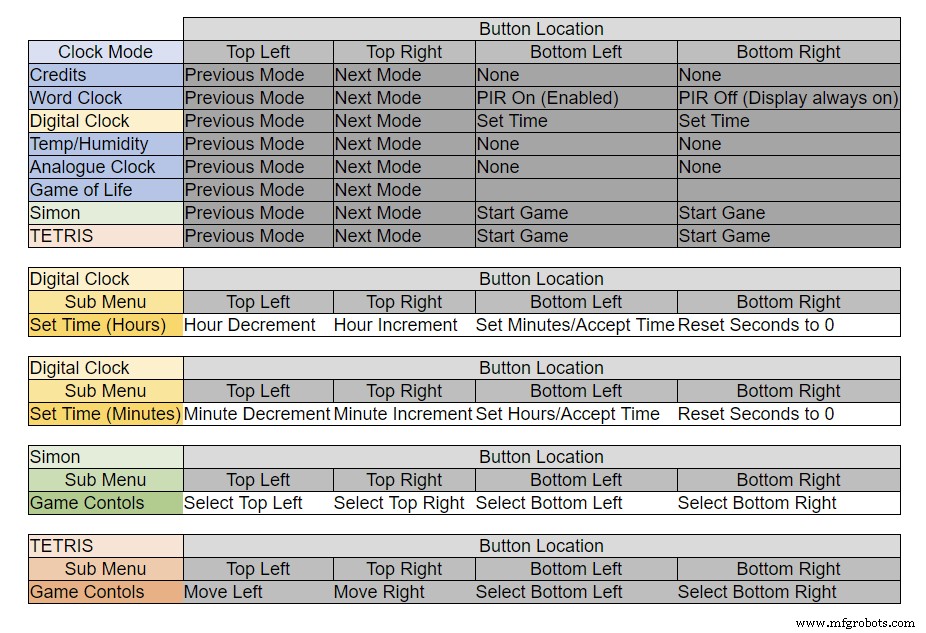
Os botões têm funções diferentes dependendo do modo em que o relógio está, consulte a tabela acima.
Etapa 5:configuração automática de verão e inverno
Não usado.
Etapa 6:modos de exibição, relógios e ambiente
A animação 1 acima mostra os 4 modos de relógio e ambiente.
Os modos são em ordem word clock, digital clock, temperatura e umidade e analógico clock.
Animação 2 acima. Também existe um modo de inicialização que percorre o número da versão do software, o nome do fabricante e o nome do relógio.
Etapa 7:modos de exibição de jogos
Três jogos clássicos são codificados no relógio. Deixei o código como está do Relógio Catalão.

Animação 1 acima do Jogo da Vida de Conway. O universo do Jogo da Vida é uma grade ortogonal bidimensional infinita de células quadradas, cada uma das quais está em um dos dois estados possíveis, vivo ou morto, ou "povoado" ou "despovoado".
Cada célula interage com seus oito vizinhos, que são as células que são horizontalmente, verticalmente ou diagonalmente adjacentes. Em cada etapa do tempo, ocorrem as seguintes transições:Qualquer célula viva com menos de dois vizinhos vivos morre, como se fosse causada por subpopulação. Qualquer célula viva com dois ou três vizinhos vivos vive para a próxima geração. Qualquer célula viva com mais de três vizinhos vivos morre, como se por superpopulação. Qualquer célula morta com exatamente três vizinhos vivos torna-se uma célula viva, como se por reprodução.
O padrão inicial constitui a semente do sistema. A primeira geração é criada aplicando as regras acima simultaneamente a cada célula na semente, nascimentos e mortes ocorrem simultaneamente, e o momento discreto em que isso acontece às vezes é chamado de um tique (em outras palavras, cada geração é uma função pura da anterior 1). As regras continuam a ser aplicadas repetidamente para criar novas gerações.
Animação 2 acima de Simon
Jogo de memória do Simon - tente e copie a sequência gerada por computador. Ao inserir sua sequência, toque duas vezes na última entrada para encerrar sua vez.
Quando você falha, sua pontuação é exibida na tela.
Animação 3 acima de TetrisTetris é o videogame soviético de combinação de peças lançado em junho de 1984. Este jogo ainda precisa de alguns ajustes nos botões para controlar as peças corretamente.
Etapa 8:Prototipagem
O relógio pode ser prototipado e testado usando os LEDs DOT Matrix originais nas placas de exibição do MAX7219.
Observe que esta modificação temporária é necessária apenas se você quiser testar seu código nos visores de matriz DOT fornecidos com os módulos MAX7219.
Isso significa que você pode experimentar as modificações do layout do software / palavra em miniatura antes de se comprometer com a versão em tamanho real. A fiação para o LED da matriz DOT terá que ser modificada para corresponder às conexões do software.
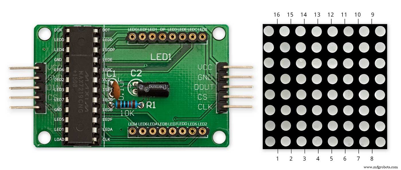
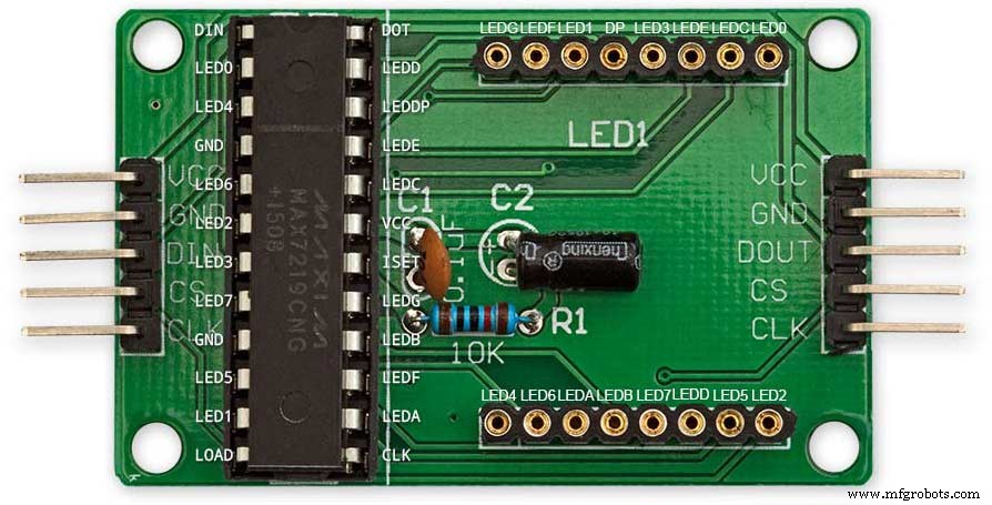
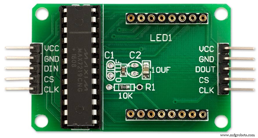
A figura acima mostra como o módulo é conectado antes da modificação. A modificação é bastante direta. Em primeiro lugar, dobre os seguintes pinos da matriz de LED 90 °, os pinos superiores para cima e os inferiores para baixo.
Pinos 16, 15, 3, 4, 10 e 11.
Insira a matriz de LED no soquete da placa de vídeo. Os pinos acima não serão conectados. Solde os seguintes fios de ligação da parte traseira do soquete da placa de vídeo aos pinos da matriz de LED que estão salientes.
LEDA para Dot Matrix Pino 16
LEDB para Dot Matrix Pino 15
LEDG para Dot Matrix Pino 3
LEDF para Dot Matrix Pino 4
LEDE para Dot Matrix Pino 10
LEDC para Dot Matrix Pino 11
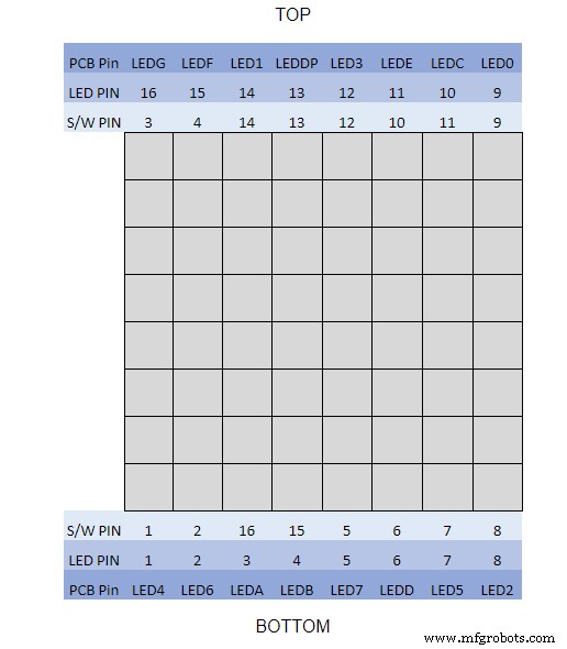
Usei um multímetro e desliguei o módulo de exibição. A Tabela mostra onde o número de pinos do software difere dos números de pinos do LED na placa do visor.
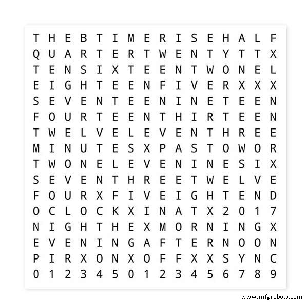
Para testar os layouts de palavras, imprima uma versão em miniatura do visor de palavras de 62 mm x 62 mm em papel branco comum.
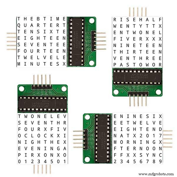
Observe a orientação das placas do visor de LED para corresponder ao layout do software.
Eu mantive a rotação da tela como o relógio Wouter Devinck original no caso de alguém usar o design Wouter Devinck PCB para o meu relógio.
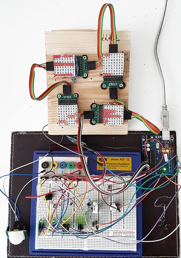
O pequeno botão abaixo do sensor de temperatura / umidade é usado para testar a sincronização de 30 segundos. Os módulos de botão de toque estão na parte inferior esquerda da placa de ensaio montados lateralmente. Não há muitos fios neste protótipo, pois a maior parte da fiação está nas matrizes da tela. No relógio final, essa fiação será feita manualmente para os LEDs individuais.
Experimentei muitos designs diferentes de word / clock neste quadro antes de tentar construir o relógio final.
Etapa 9:Teste dos módulos modificados
Modifiquei o esboço do word clock para permitir que o módulo MAX2719 seja testado após o modo de fiação.
Todo esse programa acende cada LED sucessivamente da parte superior esquerda para a parte inferior direita da matriz.
Basta conectar 5 fios ao módulo NANO e MAX2719 e alimentar o NANO a partir de sua porta USB. Carregue o esboço e deixe-o rodar.
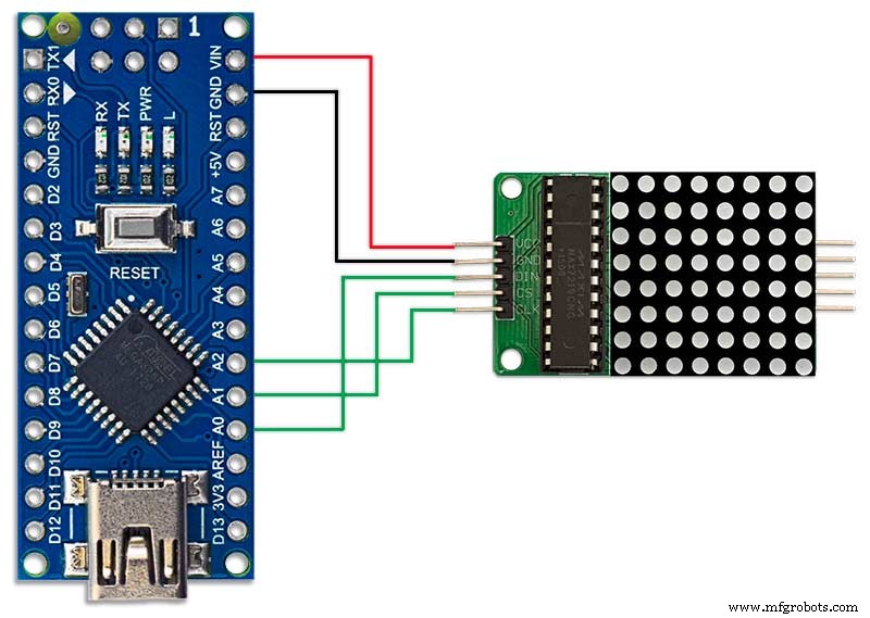
Basta conectar cada módulo para verificar a fiação.
Baixe o esboço de teste do arquivo compactado.
MAX7219_LED_Test.zip
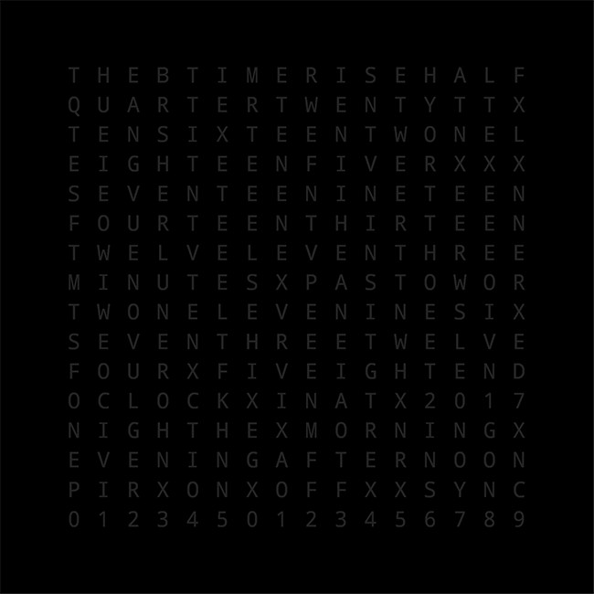
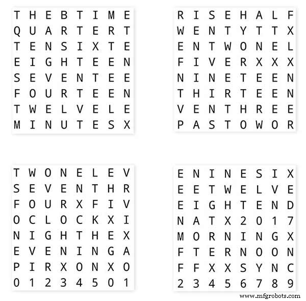
Etapa 10:Tempo para mapear a palavra
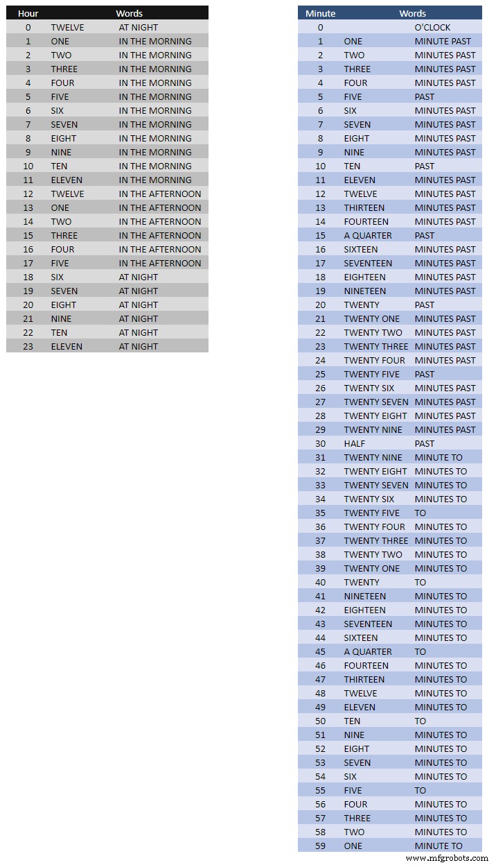
A tabela acima mostra os mapeamentos Time to Word.
Não há regras rígidas e rápidas sobre isso, basta definir as palavras como você diria as horas.
No meu relógio, mudei o seguinte em comparação com as palavras no relógio de Wouter.
"MINUTES" mudou para "MINUTE" no minuto passado e 1 minuto após a hora. Adicionado um "A" antes do "QUARTER" passado e "QUARTER" à hora.
Ao meio-dia, mudei a hora para ler DOZE HORAS DA TARDE.
À meia-noite, mudou a hora para DOZE HORAS DA NOITE.
Depois da meia-noite, o relógio sempre mostrará NA MANHÃ.
Essas mudanças são muito fáceis de implementar no software do relógio.
Palavra% 2Bto% 2BTime% 2BTranslations.xlsx
Etapa 11:Potência
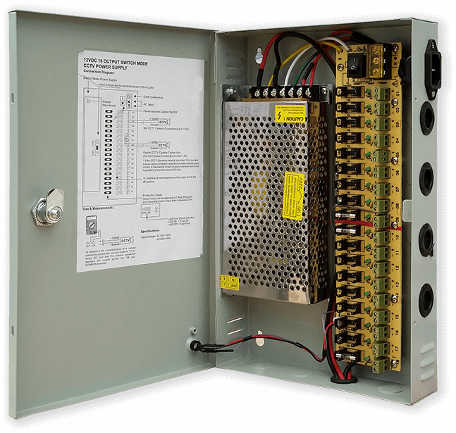
Eu uso uma fonte de alimentação comum de 12 volts para acionar muitos tipos diferentes de circuitos em minha casa. Esta fonte de 12 volts é então reduzida localmente em cada circuito com um módulo de 5 volts para fornecer energia para a placa de controle e vários módulos.
Minha fonte de alimentação comum tem 18 circuitos de 12 V com fusíveis individuais, cada um com um fusível de 2 A. 9 deles são com bateria de reserva. As placas de relógio também têm seu próprio fusível a bordo.
Se você estiver executando apenas este circuito, qualquer fonte regulada de 5 volts servirá, desde que possa fornecer a corrente para o seu uso no circuito.
Eu projetei uma placa de alimentação no Vero que usa uma fonte de alimentação em miniatura MP1584. Isso converte a saída de 12v da minha fonte de alimentação comum em 5v para o clock.
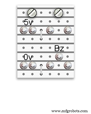
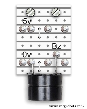
Existem duas placas de alimentação extras construídas a partir da placa Vero.
Além de 1 segurando a campainha, eles apenas adicionam pontos de distribuição de energia extras para a fiação de energia do relógio.
Requisitos de energia
Eu medi o consumo atual do relógio e com baixo brilho ele usa 30mA e brilho total 250mA. É claro que isso irá variar de acordo com a quantidade de LEDs acesos. Em um dia ensolarado, os níveis de brilho indicados na saída de série são 10. Isso é cerca de 2 terços da potência máxima dos LEDs. O consumo geral de energia pode ser bastante reduzido se o PIR estiver ligado. Isso deixará o visor em branco se o movimento não for detectado pelo relógio.
Eu usaria uma fonte mínima de 500mA para alimentar o relógio. A energia dependerá muito do tipo de LEDs que você fornecer.
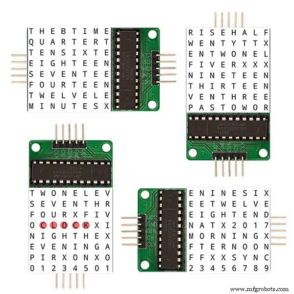
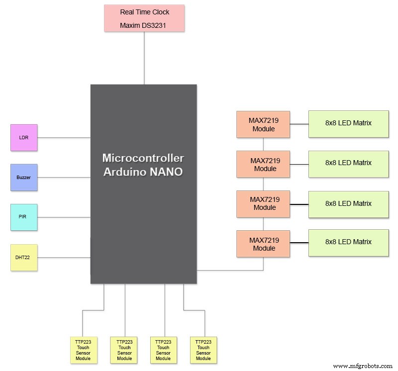
Etapa 12:Interconexões do módulo
A foto acima mostra como os módulos são conectados. A maioria dos módulos se conecta diretamente ao Arduino Nano.
As placas MAX7219 se conectam ao NANO apenas por meio do módulo 01. Os outros módulos são encadeados em série.
Cada matriz de 8x8 LEDs é então conectada a um módulo MAX7219.
A maior parte da fiação consiste nas conexões entre os módulos MAX7219 e as matrizes de LED.
Mantenha a distância entre o NANO e o primeiro módulo MAX7219 e o módulo MAX7219 aos módulos o mais curto possível. Além disso, certifique-se de fornecer energia a ambas as extremidades dos MAX7219s em cadeia, já que a maior parte da energia é consumida por esta parte do circuito.
Etapa 13:Ordem de construção
Ordem de construção presumindo que todas as alterações de prototipagem e software sejam concluídas primeiro.
Imprima a transferência de vinil.
Corte o vidro.
Corte folhas de MDF na frente e atrás.
Faça orifícios na folha frontal para LEDs.
Pinte folhas de MDF.
Faça orifícios para sensores em vidro.
Stick Vinyl transfer para a parte traseira do vidro.
Corte os orifícios do sensor na placa frontal de MDF.
Corte os rebatimentos do módulo do sensor na placa frontal.
Corte a placa traseira de MDF e faça 4 orifícios de acesso para acessar o sensor.
Adicione tiras de borda de melamina às placas de MDF, branco no painel frontal e preto no painel traseiro.
Parafuse a placa de MDF de volta à placa de MDF frontal.
Faça placas Vero, 1 placa de alimentação e 2 placas de distribuição de energia.
Modifique 4 placas MAX7219 e adicione fiação aos LEDs.
Conecte-se na extremidade MAX7219 apenas por enquanto.
Monte todos os módulos e placas Vero na parte traseira da placa frontal de MDF.
Construa todas as 4 matrizes de LED na placa de MDF frontal e solde 256 LEDs.
Ligue todos os fios Batt e Earth da placa Vero da fonte de alimentação e das placas de distribuição de energia.
Conecte todas as execuções de energia a todos os módulos.
Conecte toda a fiação ao Nano, módulos MAX7219, RTC, sensor de temperatura, sensores de toque e campainha.
Conecte todos os teares de fiação das placas MAX7219 modificadas às matrizes de LED de acordo com a tabela de fiação.
Conecte um módulo PIR remotamente a partir do relógio e conecte a conexão PIR.
Conecte a sincronização de 30 segundos ao seu relógio principal (se necessário).
Monte o painel da tela frontal do Glass usando os parafusos Chicago também fixando os sensores de toque ao mesmo tempo.
Teste.
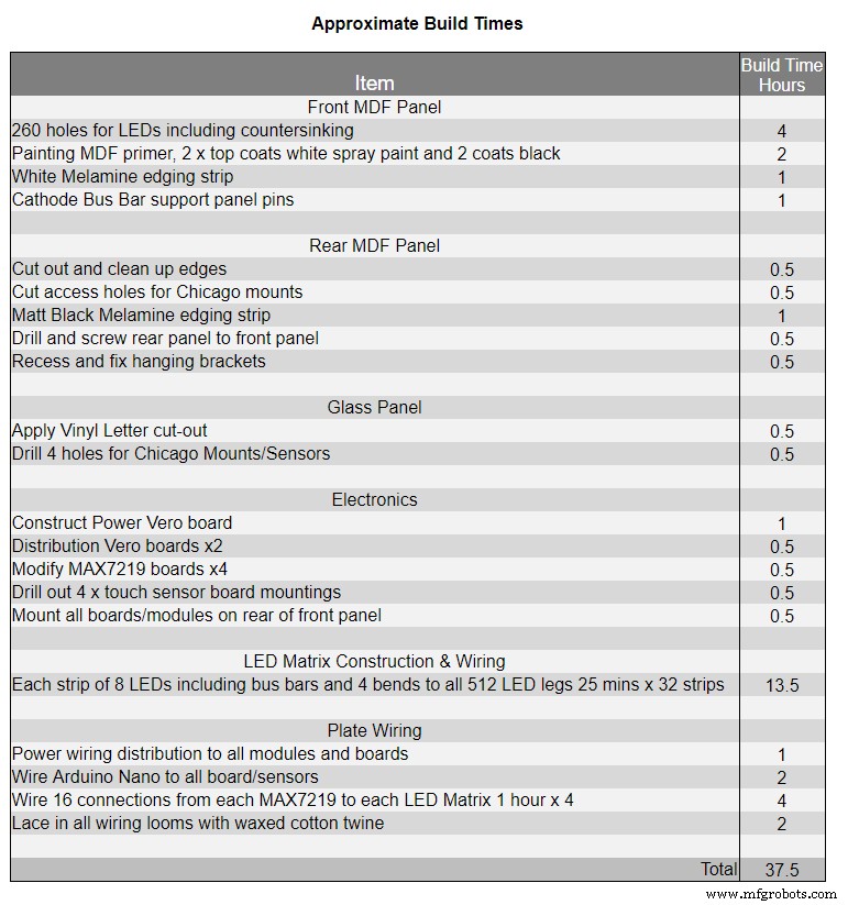
A Tabela 1 mostra os tempos de construção muito aproximados para este relógio e irão variar dependendo do seu nível de habilidade e também de quaisquer ferramentas especializadas / espaço de trabalho que você tenha à disposição.
Você pode facilmente adicionar mais 40 horas de prototipagem e programação a essa lista.
Etapa 14:adesivo de vinil para construção
Adesivo de vinil
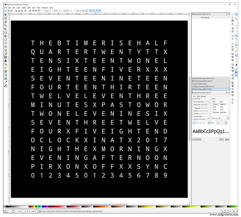
O adesivo de vinil é projetado no Inkscape.
Inkscape é um software gráfico vetorial de qualidade profissional que roda em Windows, Mac OS X e GNU / Linux. É usado por profissionais de design e amadores em todo o mundo para criar uma ampla variedade de gráficos, como ilustrações, ícones, logotipos, diagramas, mapas e gráficos da web.
O Inkscape usa o padrão aberto W3C SVG (Scalable Vector Graphics) como seu formato nativo e é um software gratuito e de código aberto.
Eu baixei o design original do Inkscape por Wouter Devinck de seu repositório GitHub e então o modifiquei no Inkscape para se adequar ao meu design. Experimentei muitas versões diferentes em meu protótipo em miniatura antes de enviar o design final para ser impresso.
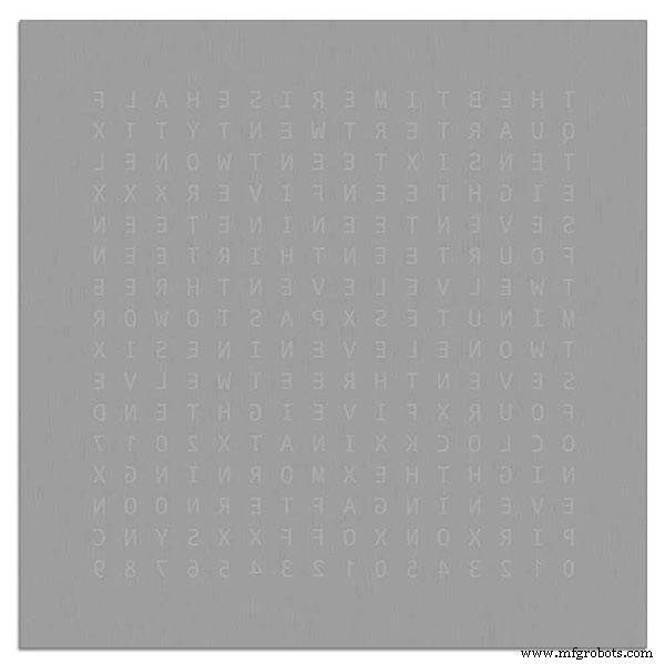
Não se esqueça de imprimir o reverso do adesivo!
Eu usei uma empresa chamada Regal Signs &Graphics que forneceu meu adesivo em vinil preto, corte reverso, letras removidas e uma fita de aplicação por cerca de £ 27 inc IVA.
Embora eles sejam bem locais para mim, paguei um pouco mais e recebi meu adesivo em um belo tubo de papelão seguro.
Tive alguns problemas para obter o design no formato correto para sua máquina, mas no final eu enviei do Illustrator em formato eps, as pessoas muito prestativas da Regal Signs redimensionaram para o tamanho correto para mim. Meu arquivo Inkscape pode ser baixado aqui ETIQUETA DE VINIL.
O adesivo de vinil veio da Regal Signs com as letras eliminadas, então isso me economizou muito tempo. O adesivo vem com uma fita plástica na parte frontal (vidro) e um papel de aplicação na parte traseira. Normalmente, você retira a fita lateral, aplica o adesivo e, em seguida, remove o papel de aplicação. Decidi deixar o papel de aplicação ligado, pois ele funcionava como um difusor para os LEDs. Como eu estava deixando o papel de aplicação, cortei o excesso de papel ao redor do adesivo antes de aplicar.
A aplicação do adesivo foi relativamente fácil. Apenas certifique-se de assistir a alguns vídeos do YouTube sobre a aplicação de adesivo de vinil no vidro antes de tentar você mesmo.
Vidro

O relógio usa vidro float de 4 mm e foi cortado para exatamente 500 mm x500 mm. Como as bordas estão expostas, as bordas também foram polidas. Tudo isso foi feito pelos meus vidraceiros locais por £ 20.
Furos de 5 mm foram então feitos no painel de vidro usando uma broca de vidro de 5 mm. Confira os vídeos do YouTube sobre como fazer furos em vidro.
Limpei o vidro primeiro com acetona e certifiquei-me de que estava livre de poeira (muito importante). Em seguida, calcei luvas de plástico para me certificar de que não deixei nenhuma impressão digital no adesivo.
Borrifei o vidro com uma mistura muito diluída de água e sabão e, em seguida, muito lentamente, retirei o filme plástico do adesivo para revelar a superfície frontal.
É importante retirar o filme lentamente e em um ângulo muito agudo para que as letras do adesivo permaneçam conectadas ao papel de transferência. Assim que o adesivo estiver completamente exposto, aplique-o na superfície de vidro úmida.
A mistura água / sabão permitirá que você mova o adesivo para o lugar correto no vidro. Em seguida, use um cartão de crédito e trabalhe longe do centro do adesivo para remover quaisquer bolhas de ar. Deixe o adesivo secar durante a noite e, em seguida, da parte de trás do adesivo, corte o vinil sobre os 4 orifícios de montagem no vidro.
Brett11_print_ready.svg
Etapa 15:Placas principais de construção, parte 1
Placas Principais
A placa principal do relógio é composta por 2 folhas de MDF 14mm. A folha posterior é 10 mm menor que a folha superior em todos os lados, exceto na parte superior. A parte superior tem bordas brancas, enquanto a parte traseira tem bordas pretas. Quando visto na parede, o relógio parecerá ter 14 mm de profundidade.
A placa principal do relógio é composta por 2 folhas de MDF 14mm. A folha posterior é 10 mm menor que a folha superior em todos os lados, exceto na parte superior. A parte superior tem bordas brancas, enquanto a parte traseira tem bordas pretas. Quando visto na parede, o relógio parecerá ter 14 mm de profundidade.
No relógio Wouter Devinck original e na versão "catalã" Pijuana, uma única folha de MDF de 18 mm de espessura é usada com a parte traseira direcionada para fora para abrir espaço para o PCB e os componentes. Usar 2 folhas de MDF significa que a tabela pode ser simplesmente cortada usando uma serra de vaivém, em vez do roteamento demorado e empoeirado. A folha superior tem 503 mm x 503 mm para dar uma sobreposição de 1,5 mm ao redor do vidro. Isso dará ao vidro um pouco de proteção contra choques.
A tabela é cortada usando uma serra de vaivém e permite 14 mm de espaço para os componentes.
O PCB mais profundo, incluindo componentes, são os módulos MAX 7219 com 10 mm de profundidade. Na conclusão, a placa traseira é colada ou aparafusada à placa frontal.
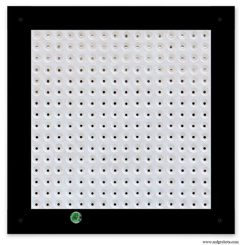
Construção do painel frontal
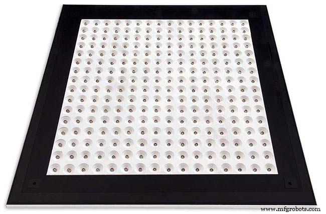
A placa frontal contém 256 LEDs que brilham através de orifícios de 6,5 mm e orifícios escareados de 18 mm para iluminar letras e números individuais no visor.
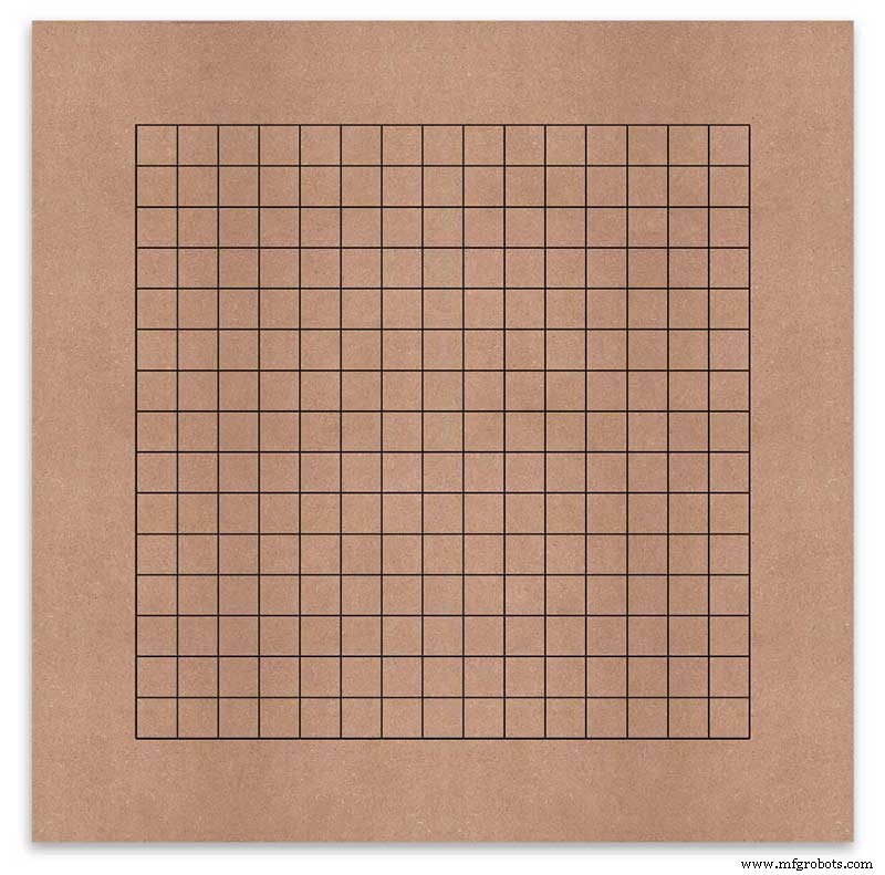
A placa é marcada para mostrar a posição de perfuração no centro de cada caractere de exibição. Usando uma tela de 500 mm, medi minha folha de vinil e os caracteres estão separados por 25 mm, começando com 62,5 mm das bordas. Desenhei essas linhas no MDF, as interseções sendo os pontos de perfuração.
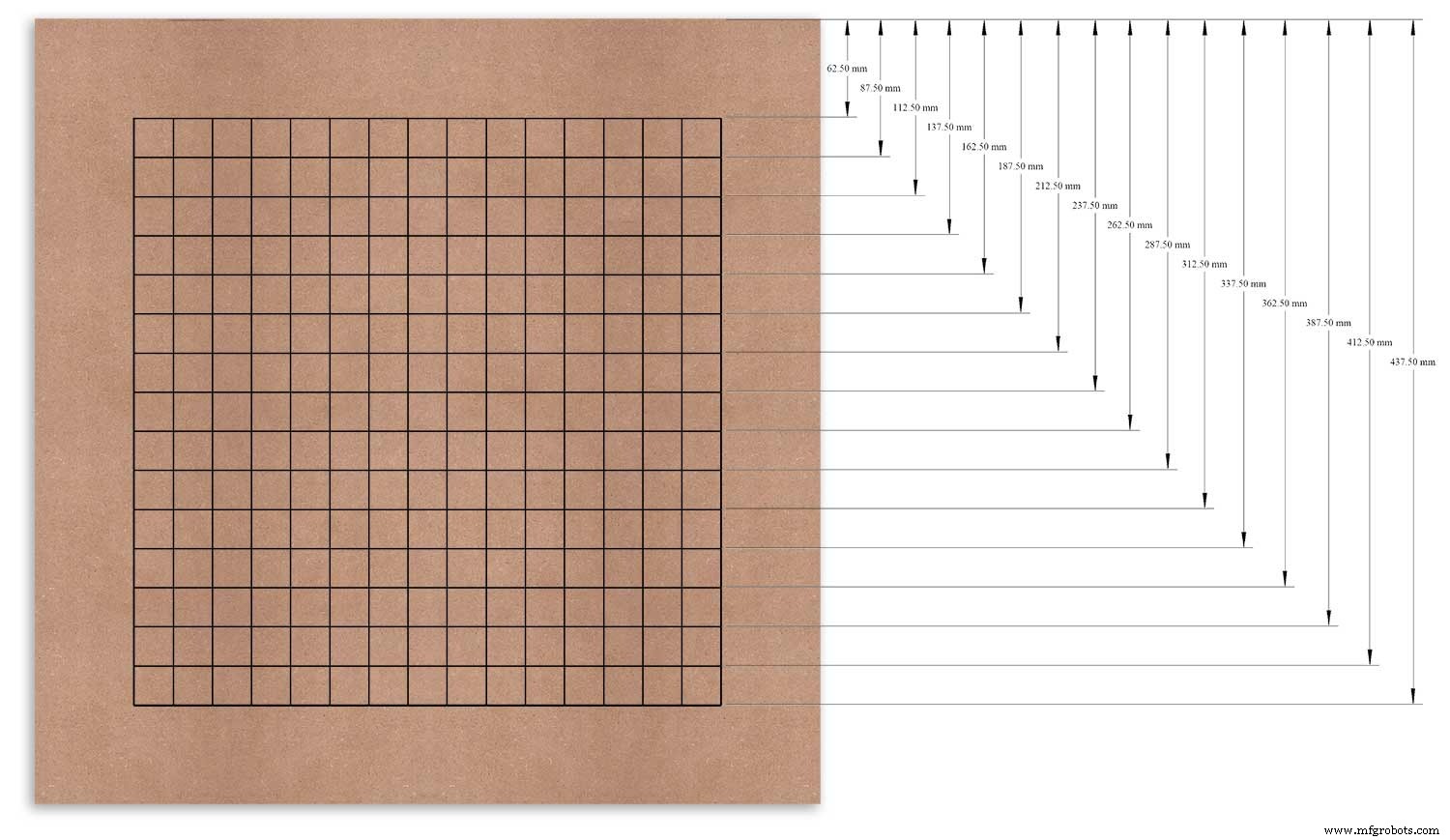
Usei a borda superior como ponto de referência, medi e marquei cada linha a partir deste ponto.
Isso foi repetido para a coluna vertical usando a borda esquerda como referência.
As interseções da grade serão o ponto central para os orifícios de montagem do LED de 6 mm e os orifícios escareados de 18 mm.
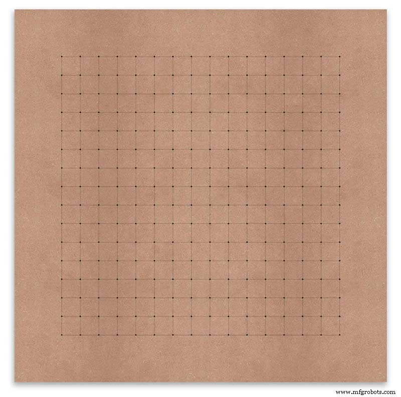
Usando um punção central automático (use um prego ou parafuso se você não tiver um), eu perfurei os 256 pontos de intersecção da grade.
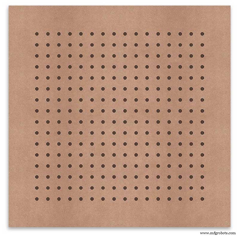
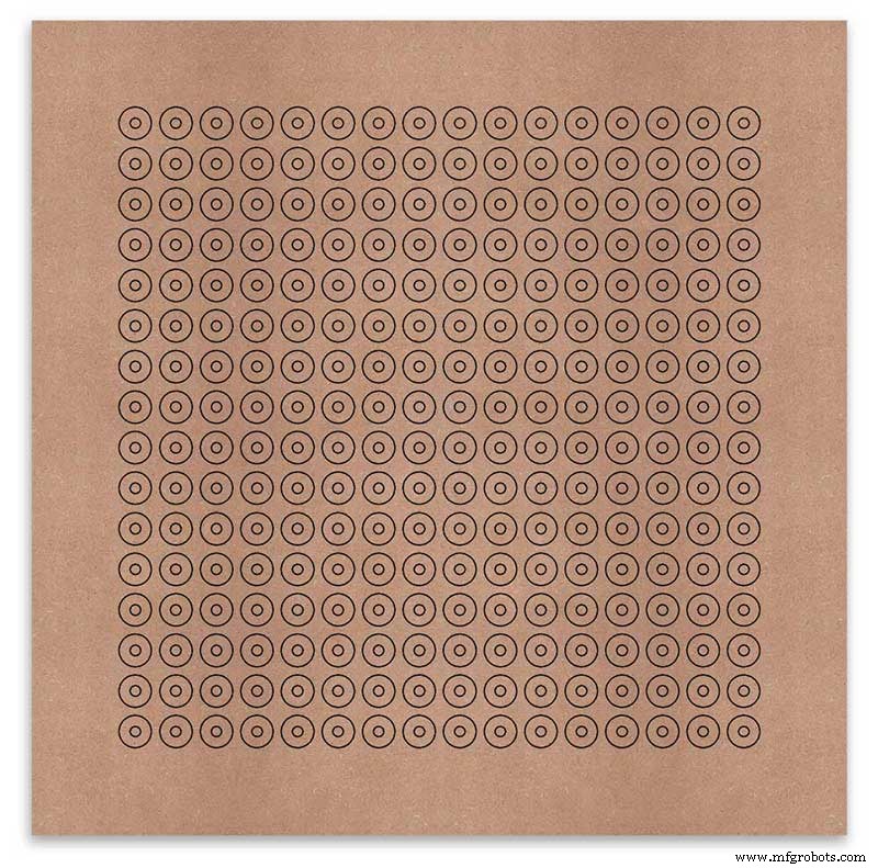
Usando uma broca para acomodar seus LEDs (6 mm no meu caso) e usando os orifícios perfurados como um guia para a broca, perfure todos os 256 orifícios de montagem de LED.
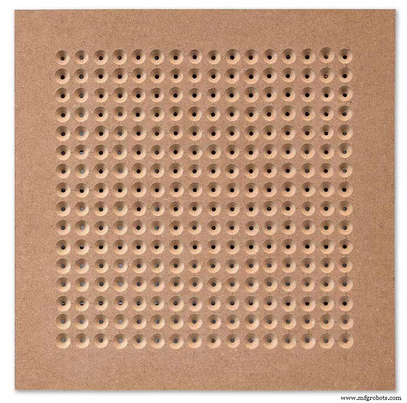
A próxima tarefa é perfurar os 256 furos escareados de 18 mm usando uma broca escareada de 20 mm.
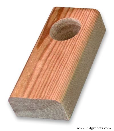
To keep the countersunk holes at a uniform depth and width I built a countersinking jig using an off cut of wood. To make the jig a hole is drilled in the wood off cut to just fit the silver rotating bezel of my drill chuck. Using a test piece of MDF the countersinking bit is then moved in and out of the chuck until a countersunk hole of the correct diameter is made when drilling through the hole upto the chuck in the off cut of wood. Once the correct distance is found the chuck is tightened and the main board is drilled 256 times by centring the hole in the wood over the existing 6mm holes then drilling down until the chuck bezel hits the hole in the countersinking jig.
Completed front board with 256 countersunk holes and 6mm holes for the LEDs.
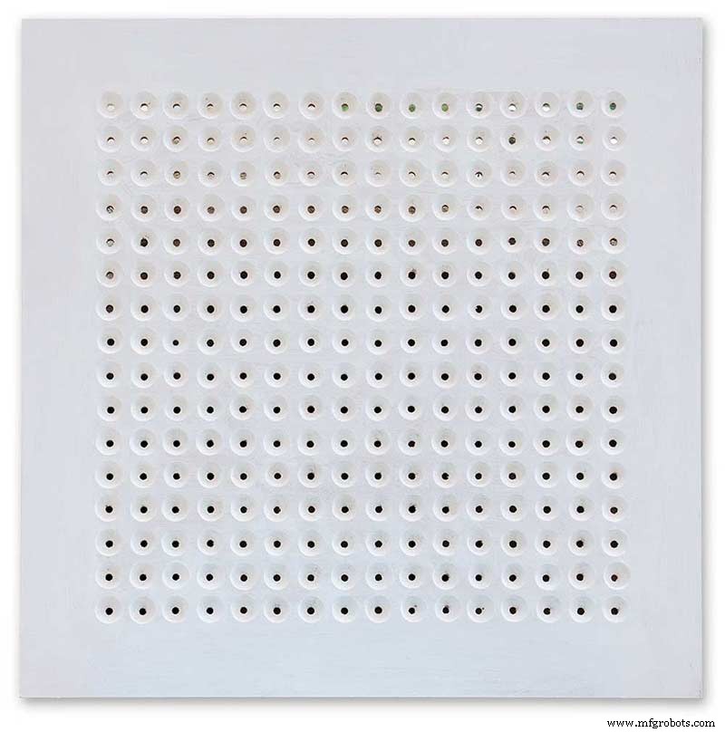
The board is then rubbed down and primed using MDF primer and painted white so the countersunk holes reflect the light from the LEDs.
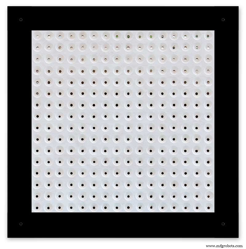
A black edge is painted around the outside edge to hide the board as the glass is 1mm shorter all round. This setback also helps the glass disappear from view on the final clock.
Four 5mm holes are then drilled in the corners to take the Chicago Fasteners. The Chicago Fasteners hold the glass in place, hold the touch sensors and provide a touch sensitive pad on top of the glass. The fasteners have 3mm shafts and will have a small bit of rubber tape wrapped around the shafts to protect the glass.
Turn the board over and drill a rebate with a forstner bit to take the four touch sensors. This hole will be offset from the hole drilled in the previous step.
Wall Mounts
The clock is fixed to the wall by two metal picture hanging mounts.
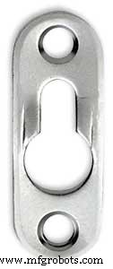
These are recessed into the frame so the highest point of the bracket is level with the frame.
Two 2" countersunk No6 screws sit in these bracket and hold the clock to the wall with a bit of tension so the dust seal is compressed.
Step 16:Construction Touch Sensor Mounting
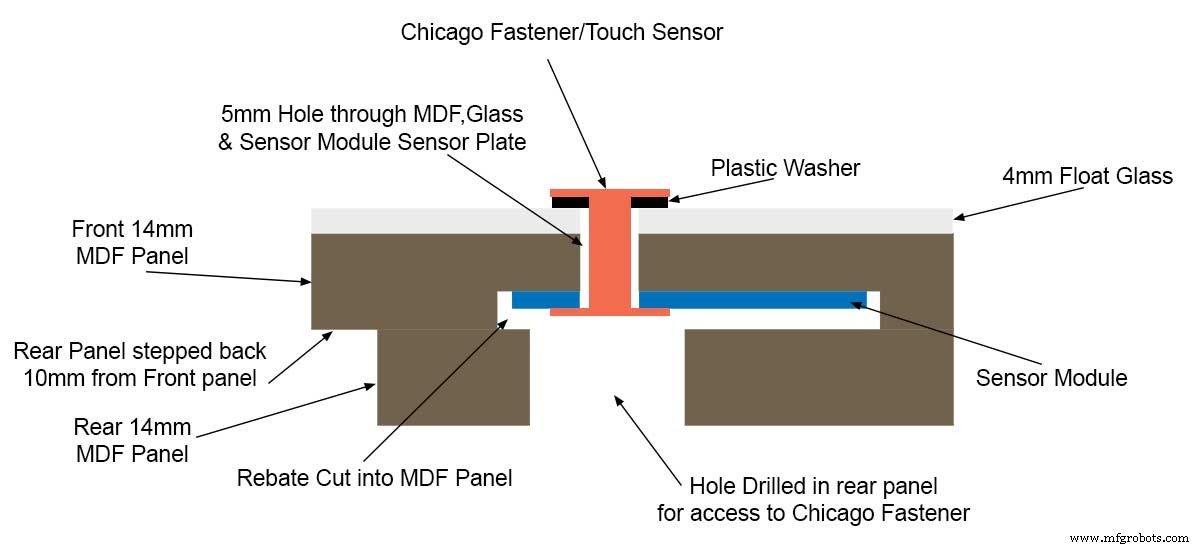
The touch sensor modules are fixed to the front panel using the Chicago Fastener bolts. The Chicago Fastener bolts then act as touch sensors.
A 5mm hole is drilled through the sensor pad on the module to allow the Chicago Fastener bolt to pass through.
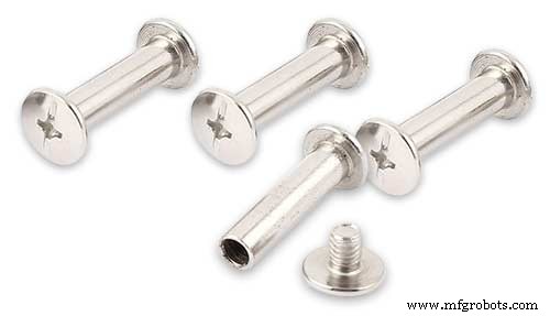
The sensor pad is insulated by the MDF panel and a plastic washer.
The touch pad on the sensor module has a 5mm mounting hole drill through the sensor.

Touch sensors in rebates behind rear panel. Holes drilled into rear panel allows access to the Chicago Fasteners that hold the sensors/glass front in place.
Clock front panel with four Chicago Fastener tops acting as touch plates.
Step 17:Electronic Components &Modules
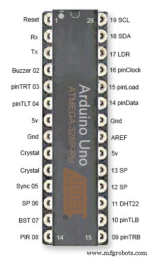
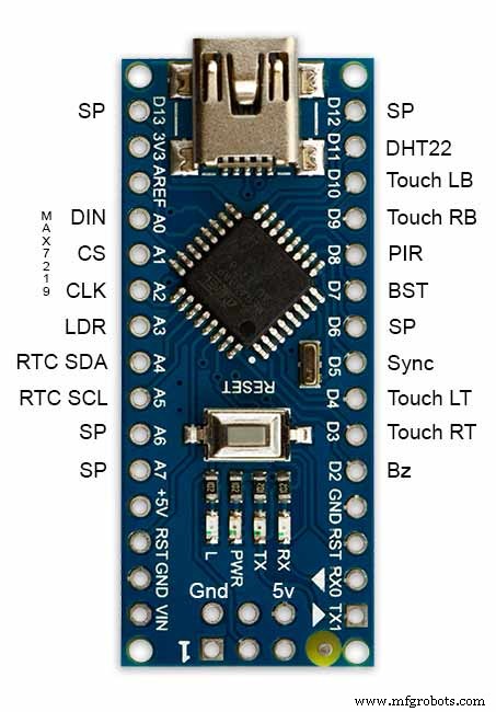
ATmega328 pin connections in case you want to prototype the circuit on an Arduino Uno. Note BST pin 07 is not used.
Pin label numbers refer to Arduino IDE numbers.
LEDs
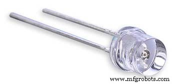
Make sure you purchase your LEDs from a good source. These LEDs will be on for many hours a day. I have has problems with LEDs failing after a few weeks use.
My LEDs Specs
5mm White Flat Top LEDs offering a pure and consistent colour with a wide angle ultra bright light output.
Colour :White
Quantity :256
Lenses Type :Round Flat Top
Crystal ClearBrightness :13000mcdForward
Voltage :3.2v - 3.8v
Forward Current :20mA (typical), 30mA (Max)
Viewing Angle :120 degrees
DHT22 Temperature &Humidity Sensor
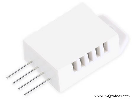
The DHT22 is a basic, low-cost digital temperature and humidity sensor. It uses a capacitive humidity sensor and a thermistor to measure the surrounding air, and sends out a digital signal on the data pin.
You can only get new data from it once every 2 seconds, so sensor readings can be up to 2 seconds old.
Simply connect the first pin on the left to 3-5V power, the second pin to your data input pin and the right most pin to ground.
To prevent the temperature of the inside clock case being measured the top and left side vent of the DH22 are covered over with tape. This also stops dust being drawn into the clock case.
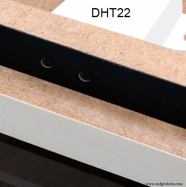
The DHT22 is mounted with its right open side mounted tight against the lower rear cover.Two small holes are drilled in the lower edge of the rear MDF board to allow air from the room to circulate around the sensor.
Arduino NANO
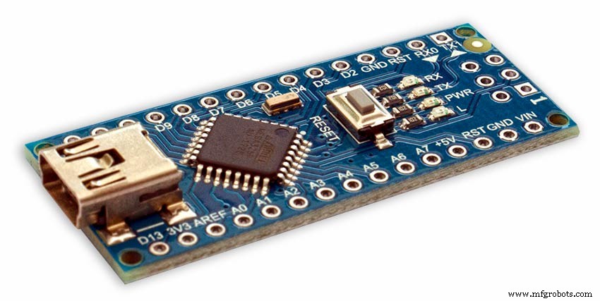
PowerThe Arduino Nano can be powered via the Mini-B USB connection, 6-20V unregulated external power supply (pin 30), or 5V regulated external power supply (pin 27). The power source is automatically selected to the highest voltage source.
Memória
The ATmega328 has 32 KB, (also with 2 KB used for the bootloader.
The ATmega328 has 2 KB of SRAM and 1 KB of EEPROM.
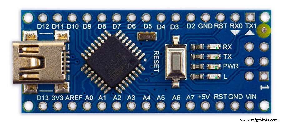
Input and Output
Each of the 14 digital pins on the Nano can be used as an input or output, using pinMode(), digitalWrite(), and digitalRead() functions. They operate at 5 volts. Each pin can provide or receive a maximum of 40 mA and has an internal pull-up resistor (disconnected by default) of 20-50 kOhms. In addition, some pins have specialized functions:Serial:0 (RX) and 1 (TX). Used to receive (RX) and transmit (TX) TTL serial data. These pins are connected to the corresponding pins of the FTDI USB-to-TTL Serial chip.
External Interrupts:2 and 3.
These pins can be configured to trigger an interrupt on a low value, a rising or falling edge, or a change in value. See the attachInterrupt() function for details.
PWM:3, 5, 6, 9, 10, and 11. Provide 8-bit PWM output with the analogWrite() function.
SPI:10 (SS), 11 (MOSI), 12 (MISO), 13 (SCK). These pins support SPI communication, which, although provided by the underlying hardware, is not currently included in the Arduino language.
LED:13. There is a built-in LED connected to digital pin 13. When the pin is HIGH value, the LED is on, when the pin is LOW, it's off.
The Nano has 8 analog inputs, each of which provide 10 bits of resolution (i.e. 1024 different values). By default they measure from ground to 5 volts, though is it possible to change the upper end of their range using the analogReference() function. Analog pins 6 and 7 cannot be used as digital pins. Additionally, some pins have specialized functionality:I2C:4 (SDA) and 5 (SCL). Support I2C (TWI) communication using the Wire library (documentation on the Wiring website).
There are a couple of other pins on the board:AREF. Reference voltage for the analog inputs. Used with analogReference(). Redefinir. Bring this line LOW to reset the microcontroller. Typically used to add a reset button to shields which block the one on the board.
Communication The Arduino Nano has a number of facilities for communicating with a computer, another Arduino, or other microcontrollers. The ATmega328 provide UART TTL (5V) serial communication, which is available on digital pins 0 (RX) and 1 (TX). An FTDI FT232RL on the board channels this serial communication over USB and the FTDI drivers (included with the Arduino software) provide a virtual com port to software on the computer. The Arduino software includes a serial monitor which allows simple textual data to be sent to and from the Arduino board. The RX and TX LEDs on the board will flash when data is being transmitted via the FTDI chip and USB connection to the computer (but not for serial communication on pins 0 and 1). A SoftwareSerial library allows for serial communication on any of the Nano's digital pins. The ATmega328 also support I2C (TWI) and SPI communication. The Arduino software includes a Wire library to simplify use of the I2C bus. To use the SPI communication, please see ATmega328 datasheet.
TTP223 Touch Sensor Module
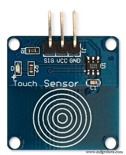
The touch Sensor Module is bolted to the front panel using the glass mounting bolts. The bolt goes through a 5mm hole drilled in the middle of the sensor.Note the mounting bolt is touched to trigger the sensor but is insulated from the sensor itself through plastic washers. Four of these modules are used in the clock one mounted on each corner of the glass.
Note the LEDs are not required and are removed from the modules (just break them off) to save power.
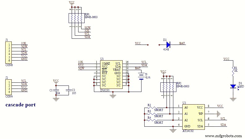
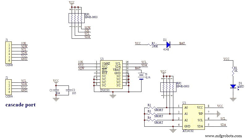
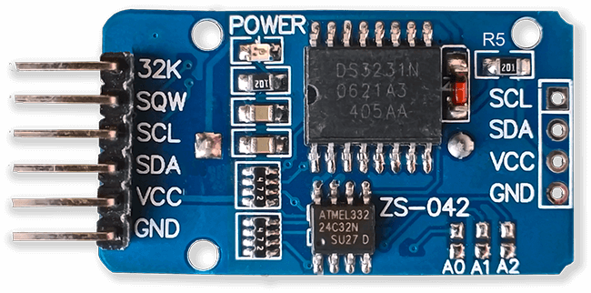
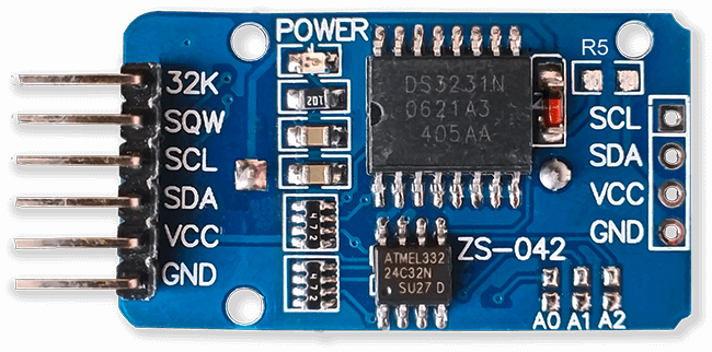
DS3231 AT24C32 I2C Precision Real Time Clock Module
My clock uses a DS3231 AT24C32 I2C Precision Real Time Clock Module.The module comes supplied with a Lithium-Ion rechargeable battery see diagram below. I use a non rechargeable battery so have removed resistor R5 from the module.
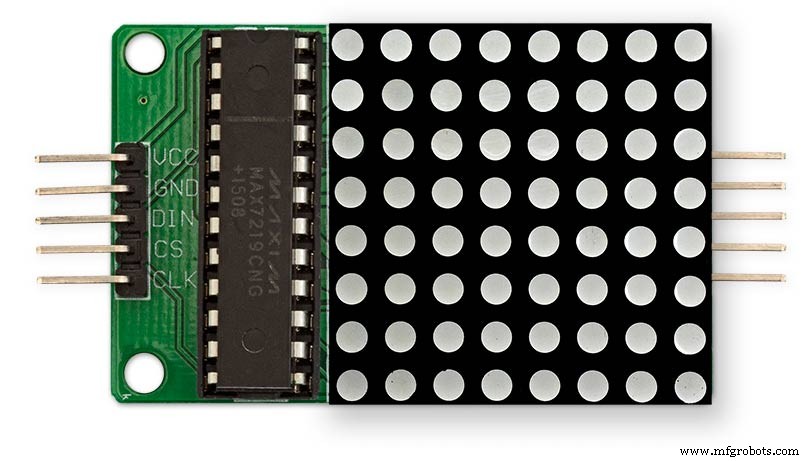
MAX7219 Display Module
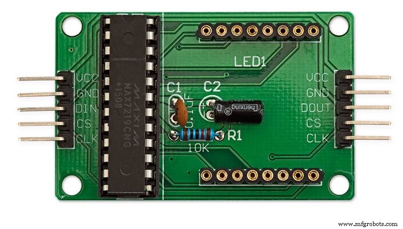
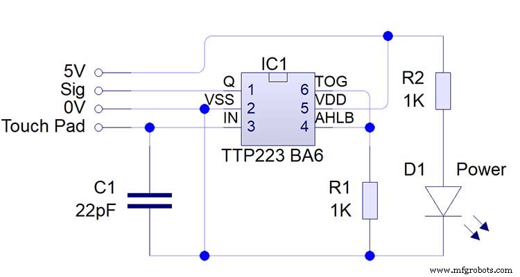
MAX7219 LED current limiting
The max current through the LEDs is set by a single resistor R1 on the module. The value of resistor can be found from the table below.
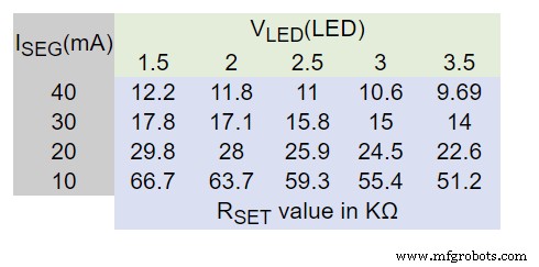
The module comes with a 10K resistor preinstalled but this can be removed and a resister to match your LEDs current added in its place. My LEDs Forward Voltage is 3.2v - 3.8v @ 20mA. They can handle 30mA max but for long LED life 20mA is best. I have used 22KΩ resistors which will limit the current to around 20mA when the light levels are at their peek.
See setting automatic brightness levels.
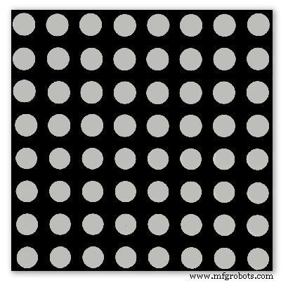
1088AS LED Dot Matrix display

1088AS LED Dot Matrix display view of lower edge Pins 1 to 8 left to right.
This is used for prototyping and is not required in the final project.
LDR
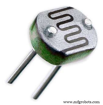
An LDR is used to sense the ambient light levels. The LDR is around 500Ω in bright light and 10MΩ in the dark.
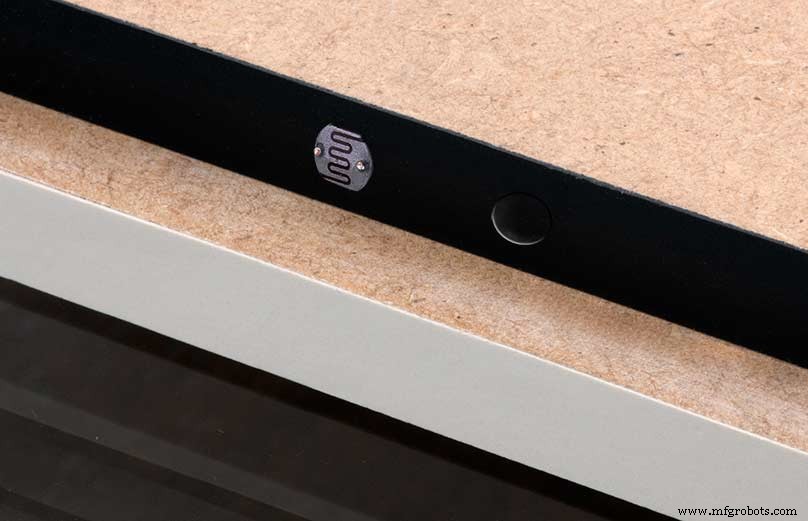
The LDR is positioned underneath the clock on the rear MDF panel.
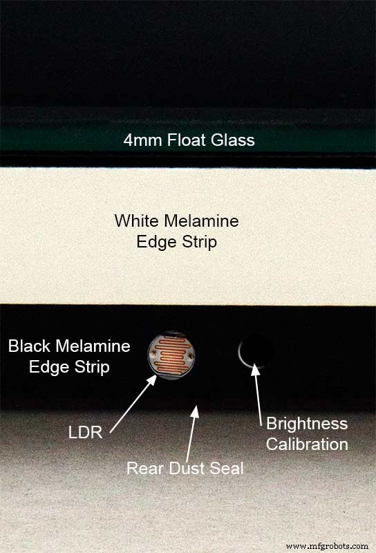
Next to the LDR is a hole to give access to the trimmer resister to calibrate the LED brightness control.
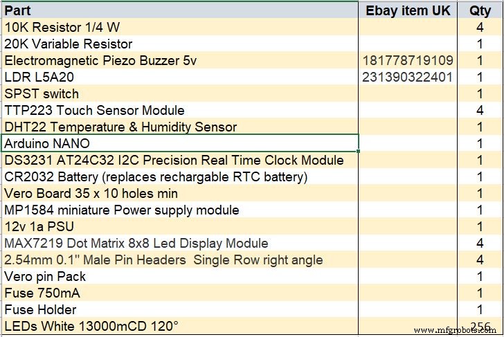
Component List
Step 18 Dust Seals
To prevent ingress of dust two dust seals are fitted.
On the rear MDF board a 2mm soft foam rubber dust seal is fitted. When the clock is hung on its hanging hooks the seal is under pressureand seals the back of the clock to the wall.
The seal is self adhesive and is fitted with a 5mm gap to the edge of the rear MDF board.
On top of the front board to prevent dust getting under the glass a strip of self amalgamating rubber is fitted 5mm from the board edge.
To prevent the glass from cracking when the Chicago bolts are tightened 4 small square of rubber are also fitted around the holes in the glass.
I punched holes for the Chicago Bolts in the rubber with a leather punch.
Step 19:Schematic
Nano Connections
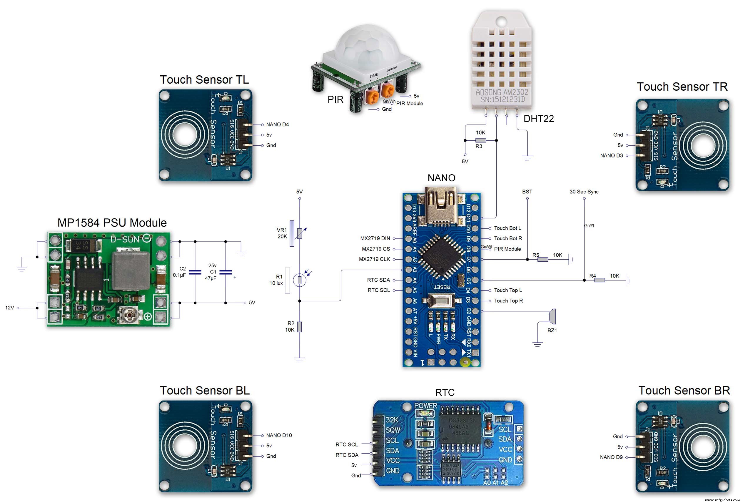
The connections to the Arduino Nano. Download the full size file from the hardware section
MAX2719 connections


The 4 MAX7219 modules and the connected LED matrixes.
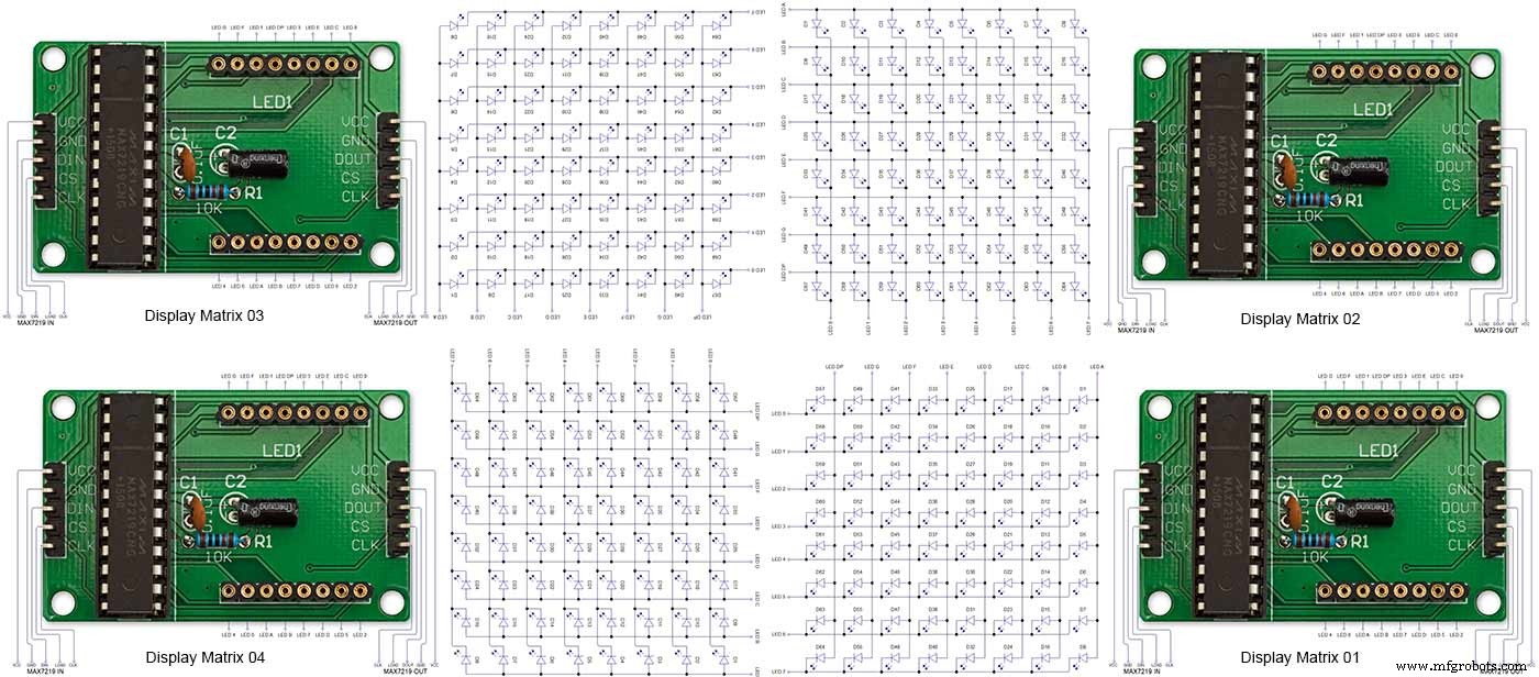
Note the LED display matrixes are rotated anti-clockwise 90 degrees from each other starting from display matrix 01.Display Matrix 01 input is wired to the Arduino CLK, DIN and LOAD the output is taken to the input of Display matrix 02 etc etc.
Step 20:Wiring Building the LED Matrixes
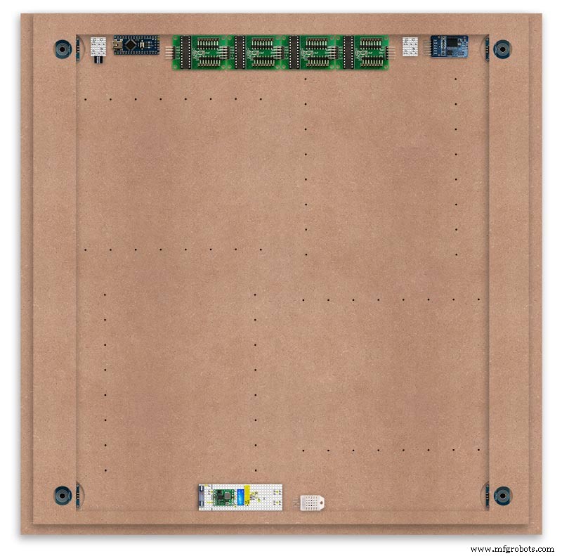
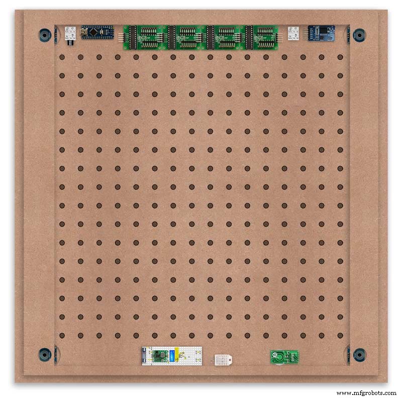
Module Locations

The module locations are shown above. The four sensors are located in the recesses on the main board behind the rear board. Holes are cut into the rear board to allow access for fit the Chicago Bolts/Sensor pads.
The four MAX7219 Display Modules are soldered together and are mounted in the centre top of the board. This keeps the data links between the boards as short as possible.
The Arduino Nano is mounted on the left of the MAX7219 Display Modules and the RTC on the right. The RTC battery holder on the base of the RTC module is recessed into the main board.
The Vero board containing the power module is located on the lower part of the board. There are two power distribution boards mounted on the top of the clock. The main 5v 2A feed cable is taken to both of these boards and power is then distributed to the other boards from these points.
The MAX7219 board power is fed from the left board and daisy chained through each board then taken out the forth board to ensure they are fed with 0v and 5v from both ends.
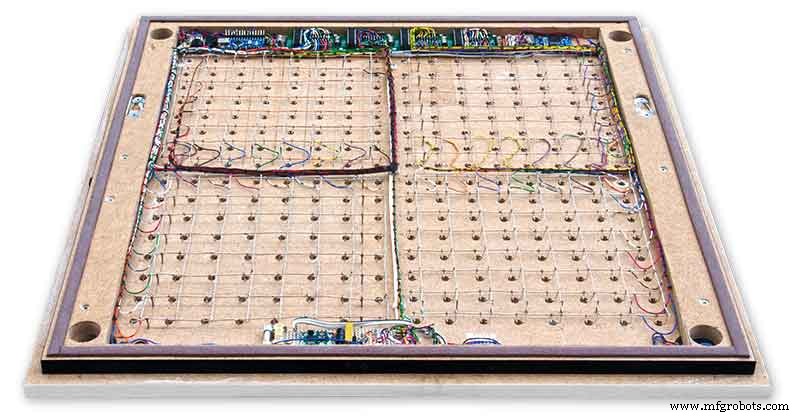
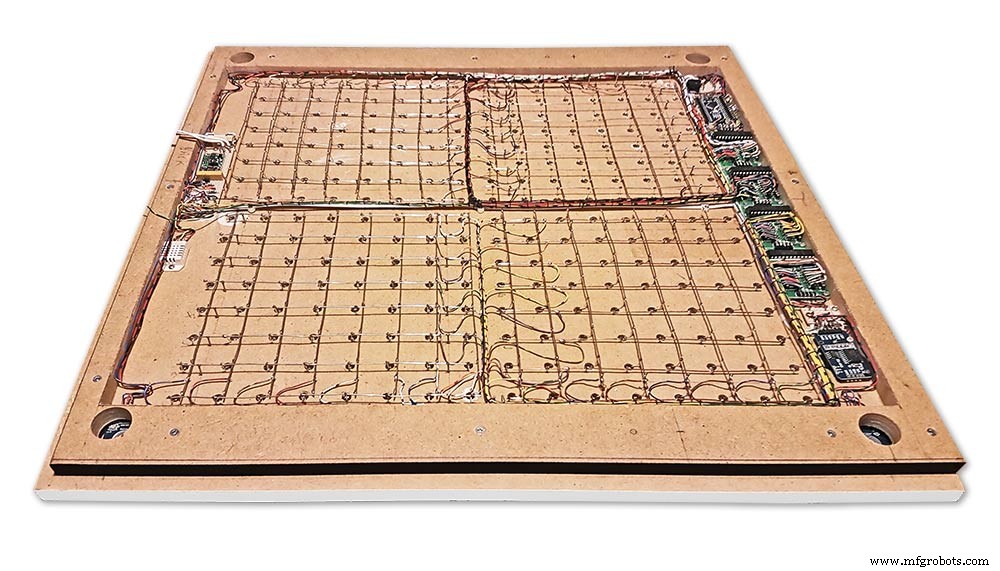
The LED locations are shown. The LED matrixes each contain 64 LEDs and are labelled 1 to 4.
These correspond to the 4 MAX 7219 modules mounted above numbered 1 to 4 left to right. Note this is the rear of the clock so number will be revearsed.
The LED Matrixes are built up off 2 types of BUS Bars per module. A Cathode Bus at 10mm high and an Anode BUS bar at 2mm high.
There are 8 Cathode and 8 Anode BUS Bars per module. Each module has 16 x 15mm panel pins hammered into the board in the position shown to support the 10mm high Cathode BUS.
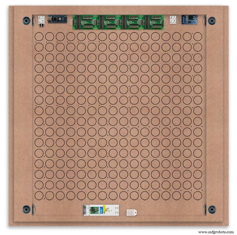
The 15mm panel pins are hammered in 5mm (I used a 10mm piece of metal bar as a gauge) leaving 10mm as Cathode BUS bar support pins.
As shown above the pins correspond with the thick parts of the board not the recess for the LEDs on the front of the board. Note the LED recess is on the front of the board and can't be seen from the back.

0.9mm copper wire is then soldered to each pair of pins to form the Cathode BUS Bar.
Note the rotation of each module and also the modules are in reverse as it is the back of the board the LEDs are connected to.
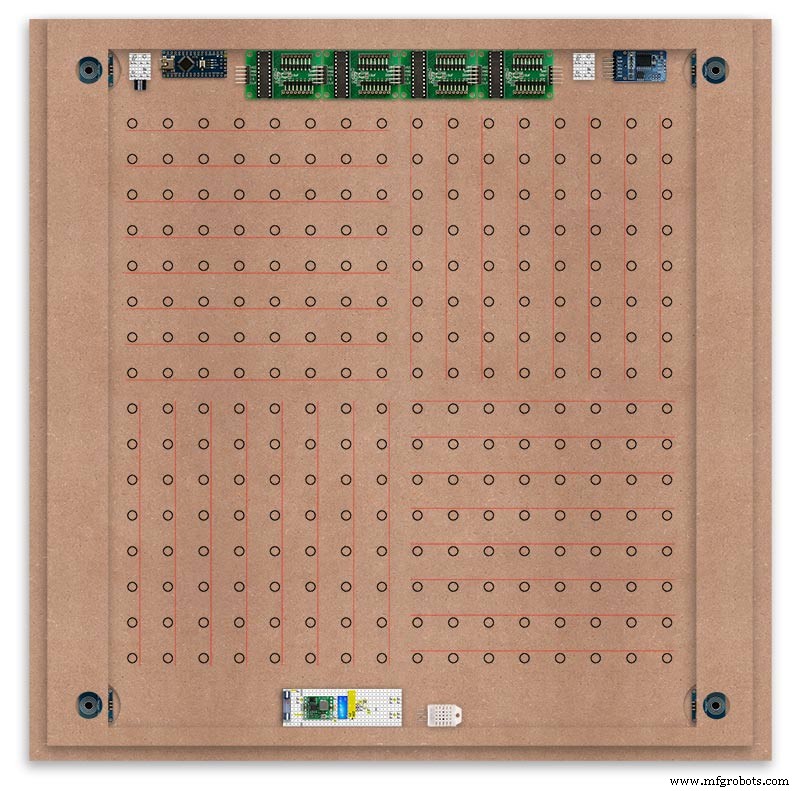
The Anode BUS Bars are shown below in Red and are supported off each LED Anode about 2mm off the MDF board. No Pins required.

Both Cathode &Anode BUS Bar locations are shown below.
Each LED is connected to an Anode and Cathode of the Matrix.
Step 21:Wiring the LEDs
LEDs
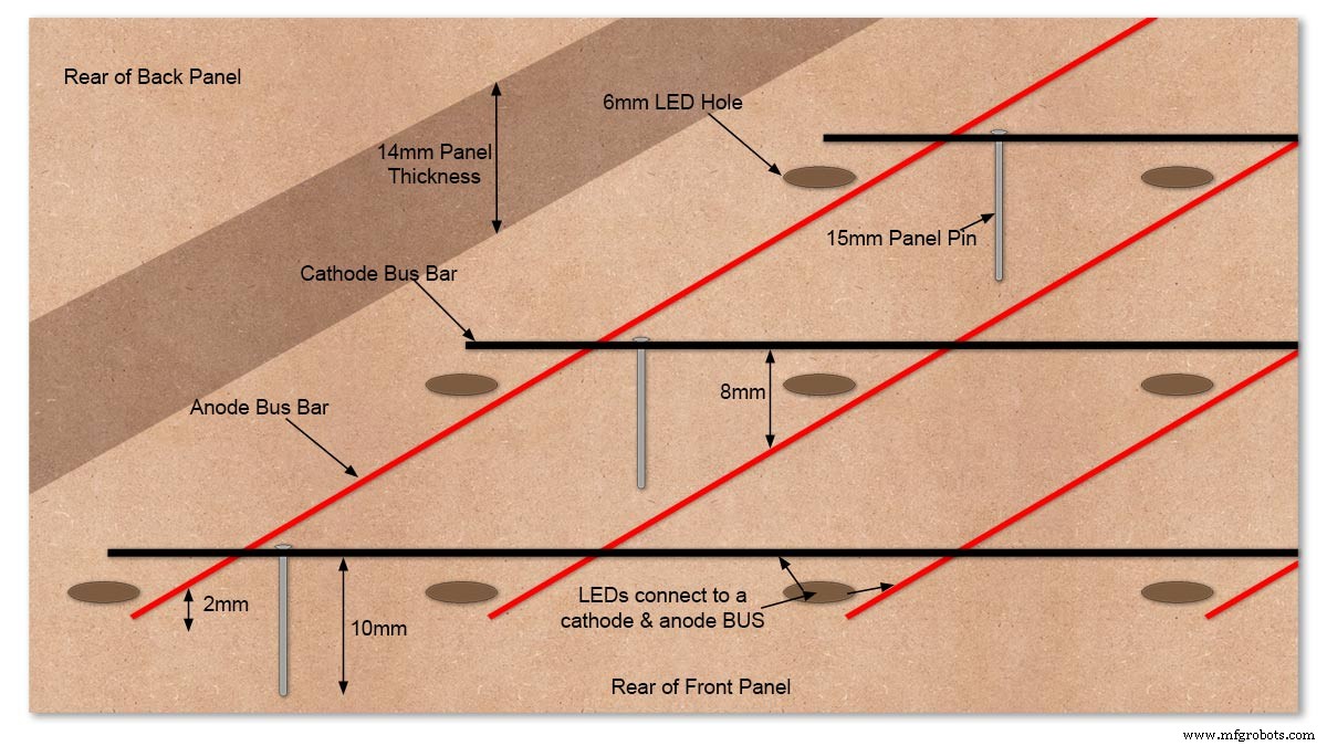
Diagram showing Bus Bar layout with panel pins supporting the Cathode Bus. This module has horizontal Cathode and vertical Anode Bus Bars.
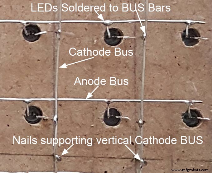
Close up section of Module wiring.The Cathode BUS Bars run vertically and the Anode BUS Bars run horizontally on this module. The Anode &Cathode BUS Bars have an 8mm vertical separation.
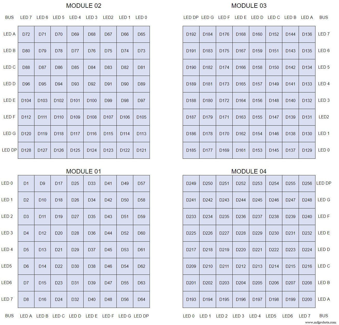
The LEDs are connected to the matrixes and MAX7219 modules from the rear. The LED positions will be reversed and of course rotated 90° relative to the next module. This makes it very complicated connecting the correct LEDs and Bus bars from the rear of the board. The table below shows the LED positions in the blue boxes with the BUS Bar matrix position in black around the outside as they appear from the back of the front MDF board.
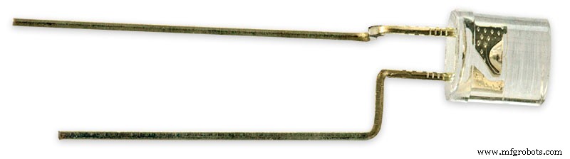
The LEDs are bent in a jig to keep the position in the display constant and to speed up construction. Each LED has four bends two on each leg that's 1024 in total! The Cathode leg is bent 90° from the Anode.
The Matrix grids are wired to the corresponding pins on the MAX7219 modules according to the layout table.
There are 16 wires to each module.
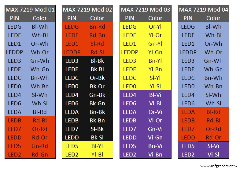
Table 1 Module LED Matrix Wiring Colour Code is shown above.
Each Module has 16 wires connecting it to the LED Matrixes. I have used 50pr 0.5mm cable so the last 14pr colours are duplicated. On Mod 4 I went out of order and missed out the Sl/Vi at the start so have put it in at the end.
Step 22:Wiring Modifying the MAX7219 Modules
Before wires can be connected to the MAX 2917 modules they will need to be modified.
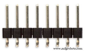
Two sets of 8 90° pin connectors will to be soldered to the lower edge of the existing LED matrix connector.

Modified MAX7219 module with 90° pin connectors soldered in place to the bottom of the old LED Matrix connectors.
Wires are taken away from these points to the LED matrix on the main MDF board as per the LED Matrix Wiring Colour Code table on the previous step.
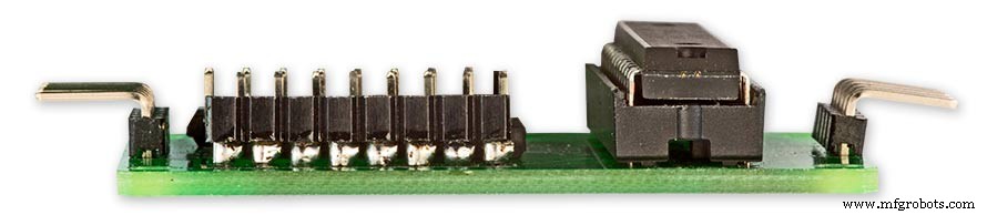
Side view showing the pins soldered to the side of the old LED Matrix connector pins just above the PCB.
Note if your MAX7219 Module does not have surface mount components the 90° pin connectors may need to be trimmed back so they don't foul R1, C1 or C2.
MAX7219 LED current limitingThe max current through the LEDs is set by a single resistor R1 on the module. The value of resistor can be found from the table below.

The module comes with a 10K resistor preinstalled but this can be removed and a resistor to match your LEDs current added in its place.
My LEDs Forward Voltage is 3.2v - 3.8v @ 20mA. They can handle 30mA max but for long LED life 20mA is best. I have used 22KΩ resistors which will limit the current to around 20mA when the light levels are at their peek.
Note this sets the max current through your LEDs actual brightness is controlled by the LDR/software/ trimmer resistor and will usually be far less than this.
Setting Automatic Brightness Levels
The clock automatically senses the ambient light and adjusts the LEDs accordingly.
When first installed the clock will need to be calibrated to the maximum light levels in its actual location.

Connect a mobile, laptop/tablet etc via a suitable cable to the mini USB port of the clock and open an app to monitor the serial port.
I use Slick USB 2 Serial Terminal on my S7 via an OTG cable and USB to mini USB cable.
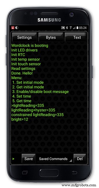
The clock will reboot and after the initial start screen you will see the following data updating down the screen.
You don't need to worry about lightReading or constrained lightReading+hyster just light reading, and bright.
With the clock in position and the ambient light at its maximum levels carefully insert a flat bladed jewellers screwdriver into the access hole just to the right of the light sensor.
Turn the screwdriver slowly until the light reading =600 (or your level set in brightness.cpp) and bright =15.
Your clock will now go to max brightness when the ambient light is at its maximum.
If you turn the screwdriver too far the light reading will go over 600 but the bright reading will not increase.
If you want the clock to be dimmer right across the range of ambient light levels adjust the light reading to a level less than 600 at max ambient light levels.
Note when bright=15 this will output the max current to the LEDs. The max current is set by R1( RSET) on the MAX7219 module and this should be chosen for your type of LED used in the display.
Step 23:Wring Mini USB Port
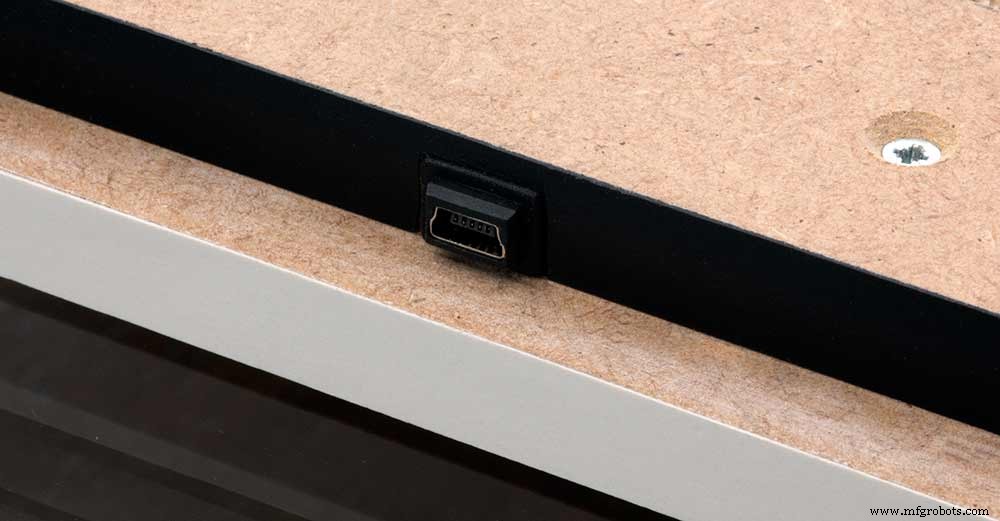
To allow adjustment/checking of light levels and programming of the clock a Mini USB socket is cut into the right hand side of the rear MDF sheet.
I have used a 25cm 90° Right angle Mini USB Male to Female Extension Cable and stripped back the insulation sleeve and shielding to expose the wires. This allows the cable to bend around the sharp angles and tight spaces of the enclosure.
Step 24:PIR Controlled Display Shutdown
This is optional as a Doppler Radar module can be fitted inside the clock instead.
See next section.
The PIR when enabled on the word clock menu (bott left PIR On, bott right PIR Off) turns on the display when movement is detected in the room.
When no movement is detected the display turns off after a set period of time. When the PIR is enabled the displays shows "PIR ON" and when disabled (display always on) it shows "PIR OFF" Note when the PIR is not enabled the display is always On.
The PIR module is fitted remote from the clock in a modified chrome light switch box. The box is cut into a plasterboard wall and also contains a switch to turn the clock off. The module itself is very small and can be mounted in a tiny enclosure if you don't want it on show. It will not work behind glass so if you wanted to mount it on the clock a hole would need to cut in the glass. This is very easy to do with a large hole cutter.
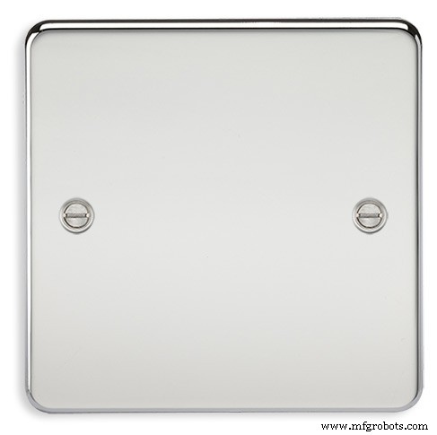
A blank chrome switch plate and back box are used to house the power switch and PIR module.
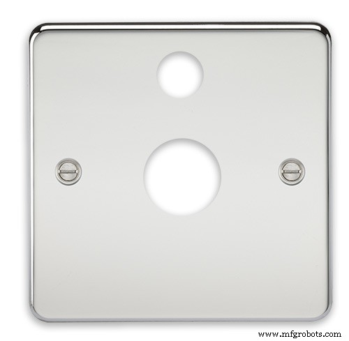
Two holes are drilled in the blank switch plate for the power switch and PIR lens.
The hole are centre punched, pilot drilled and then drilled out just big enough for a step cutter to fit through. The hole for the PIR diffuser is cut just big enough for the lens to go through with a friction fit.
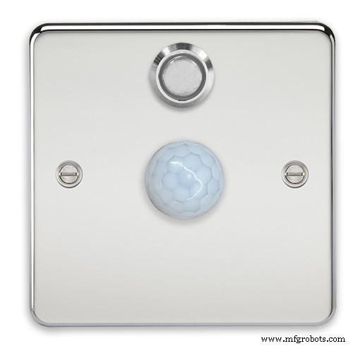
The completed switch plate.
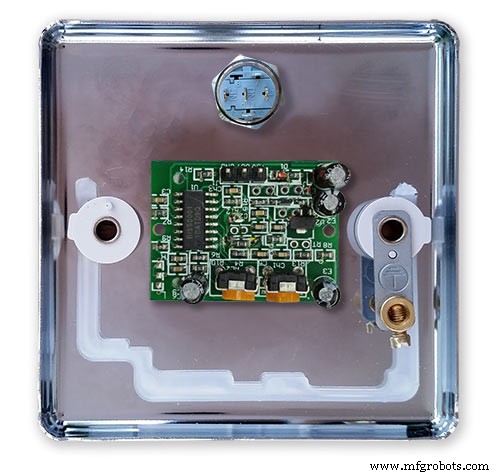
The 12 volt supply +ve is terminated on the switch with the 0v terminated on the earth screw.
12 volts is then fed back upto the clock PSU Vero board from the other side of the switch and again the earth screw. 5 volts are fed from the clock PSU Vero board to supply the PIR module.
The 5 volts and PIR sensor wire to the clock terminate on PCB header sockets. These are is plugged into the PIR Module header pins. The sync cable is terminated on a header pins and connects to the Master Clock 30 second sync cable via a single header socket.
The PIR has 2 trimmer resistors for adjusting sensitivity and also length of time the PIR &display stay activated.
PIR On/Off Control:The PIR is turned on and off in word clock mode by touching the bottom left sensor to turn the PIR on or by touching the right sensor to turn the PIR off. Note when the PIR is set to off the display stays on permanently. When you change the PIR setting the work "PIR ON" or "PIR OFF" is displayed for 5 seconds.
When initial power up the default is PIR off if you switch the PIR On straight away the display will go off as the PIR takes a minute or so to initialise before detecting movement.
Photo 6 &7 "PIR ON" or "PIR OFF" are displayed for 5 seconds when PIR setting is changed.
Step 25:Doppler Radar Control Option
Optional Doppler Radar Module can be added in place of the PIR above.
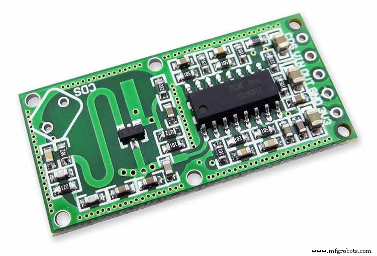
The Doppler Radar when enabled on the Word Clock menu (bott left PIR On, bott right PIR Off) turns on the display when movement is detected in the room. A check is made for motion on every quarter hour. When no movement is detected the display turns off until movement is detected again.
When the PIR is enabled the displays shows "PIR ON" and when disabled (display always on) it shows "PIR OFF" Note when the PIR is not enabled the display is always On. Unlike PIR modules the Doppler Radar module can see through glass and plastic and is fixed into the case of the clock behind the glass and PVC sticker. The module has a range of around 5m or 16' 5".
Doppler Radar Module fixed inside the case. A hole is drilled in the front panel to allow the module to monitor the room.
Front panel showing hole through to the Doppler Radar module microwave sensor.
The module is hidden from view behind the PVC sticker and glass.
Step 26:PIR/Doppler Radar On Off Control
The PIR is turned on &off in word clock mode by touching the bottom left sensor to turn the PIR on or by touching the right sensor to turn the PIR off.
Note when the PIR is set to off the display stays on permanently.

When you change the PIR setting the work "PIR ON" or "PIR OFF" is displayed for 5 seconds.
When initial power up the default is PIR off if you switch the PIR On straight away the display will go off as the PIR takes a minute or so to initialise before detecting movement.
Step 27:Setting Automatic Brightness Levels
The clock automatically senses the ambient light and adjusts the LEDs accordingly.
When first installed the clock will need to be calibrated to the maximum light levels in its actual location. Connect a mobile, laptop/tablet etc via a suitable cable to the mini USB port of the clock and open an app to monitor the serial port. I use Slick USB 2 Serial Terminal on my S7 via an OTG cable and USB to mini USB cable.

The clock will reboot and after the initial start screen you will see the following data updating down the screen.
You don't need to worry about lightReading or constrained lightReading+hyster just light reading, and bright.With the clock in position and the ambient light at its maximum levels carefully insert a flat bladed jewellers screwdriver into the access hole just to the right of the light sensor. Turn the screwdriver slowly until the light reading =600 (or your level set in brightness.cpp) and bright =15. Your clock will now go to max brightness when the ambient light is at its maximum. If you turn the screwdriver too far the light reading will go over 600 but the bright reading will not increase.
If you want the clock to be dimmer right across the range of ambient light levels adjust the light reading to a level less than 600 at max ambient light levels.
Note when bright=15 this will output the max current to the LEDs. The max current is set by R1( RSET) on the MAX7219 module and this should be chosen for your type of LED used in the display.
Step 28:Setting the Clock
The clock is set in the digital clock mode by touching the bottom left sensor.
The hour digits will now flash twice a second to indicate the clock is in time setting mode.In this mode the sensors have the following functions.
Top right - steps the hours or mins digits up
Top left- steps the hours or mins digits down
Bottom left 1sr press - enters the time setting mode selecting hours digits
Bottom left 2nd press -selects the mins digits for changing
Bottom left 3rd press -exits time setting mode and sets the time
Bottom right - resets the seconds to 00
Step 29:Synchronisation
If you have connected a 30 second master clock sync cable then the clock will jump back or forward to 30 seconds when out of time setting mode. If you don't have a Master Clock to sync to then the clock will fall back on the on board temperature compensated real time clock which in itself is a very precise quartz clock.
Just reset the seconds roughly in sync to the seconds (within 10 seconds either way) and wait for the clock to sync once out of time setting mode.
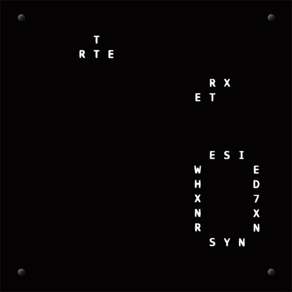
The animated loop below shows the Word Clock is running fast by several seconds. A synchronisation pulse is received from the Master Clock every 30 seconds on the minute and half minute synchronising the clock on 30 seconds.
The clock will ignore the 30 second synchronisation pulse from the Master Clock at 0 seconds. Note clock synchronisation only happens when the Word Clock is 20 seconds past and 20 seconds to a minute. In normal operation the sync pulse corrects the clock to within a fraction of a second so you will see the word "SYNC" appear with no visible correction to the seconds.
Note the synchronisation pulse is received every 30 seconds but the clock will ignore pulses at 0 seconds.
Step 30:Software &Making Changes
The software can be downloaded from the software tab and contains the following modules.
Program Files Modules
Brett_wordclock_v4_3.ino Main program, latest update includes shortened code saving 10% in size.
Thanks to srdevil for providing the updated code for this seconds display.
brightness.cpp/.h Brightness autoadjustment
character.cpp/.h Character (digit) definitions
credits.cpp/.h Ending Credits
display.cpp/.h Display &LED functions
life.cpp/.h Game of Life
serial.cpp/.h Serial port setup menu
simon.cpp/.h Simon Says game
temphum.cpp/.h Temperature &Humidity displa
tetris.cpp/.h Tetris game
time.cpp/.h Wordclock, digital clock
timeanalog.cpp/.h Analogue clock
touchbuttons.cpp/.h Touch buttons, mode switching
Third party libraries:
Chronodot.cpp/.h Chronodot library (for DS3231)
DHT.cpp/.h Temperature sensor library (for DHT22)
LedControl.cpp/.h LedControl library (for MAX7219)
stc.cpp/.h/platform.h Simple Tetris Clone library
pitches.h Note frequencies from the Arduino webpage
When you want to make changes to my code you can compare my code to the "Catalan Code" to make it easier to understand what changes you need to make. I have added //Brett to my code to highlight my changes.
Changing the code.
If like me you are not very good at coding just play around with the code to get an understanding of how it works.
I just save a different version each time I make even a tiny change. This way if I mess up I can go back a version and start again.
If you are keeping my linear seconds display update the version number on the display so you know what version you are trying out each time. This is done in the module credit.h around line 47.
It would take far too long to explain all the code but here is a very brief guide on how to change the words and when they are displayed.
The WORDS are set in time.h
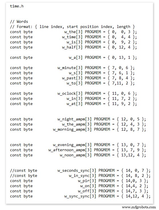
On line 52 we have
const byte w_the[3] PROGMEM ={ 0, 0, 3 };
The word "THE" is described in this line with the LED location in the curly brackets "{ 0, 0, 3 }"
This is the co-ordinate of the LEDs we are gong to light when we call "w_the"
The LED matrix numbers starts top left and start from 0 so "{ 0, 0, 3 }" is the first LED across and down the 3 just means the 3 LEDs across including this one will light. As the letters THE are in this position the word "THE" is displayed.
Similarly the word "TIME" would be lit by lighting the four LEDs here { 0, 4, 4 } or row 0, 5th LED along and light 4 LEDs (remember to count from 0).
Working you way down the page shows the position of all the words.
Controlling when words are lit
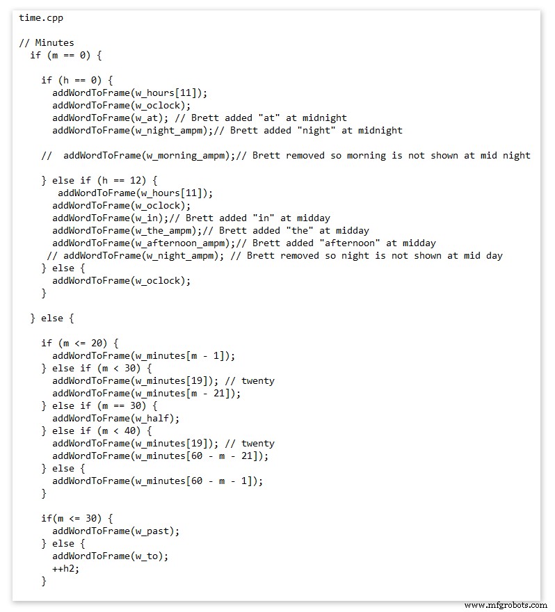
This happens in the module time.cpp
Here you just make a list of rules to tell the clock what words to light at certain times.
Pic above shows part of the code starting with line 695
At midnight we want to make the clock say "THE TIME IS TWELVE OCLOCK AT NIGHT"
Midnight is 00 00
"THE TIME IS" is always displayed from lines 687
So we add the rules if minutes are 0, then if hours are 0 show the word for hours "TWELVE" and the word "OCLOCK" the word "AT" and the word "NIGHT"
If you follow the code down all the possible time combinations are covered.
Analogue Clock Code Change - increase in time definition One of the comments sent to me by srdevil was some code changes. His comment can be seen below.
I have not had time to test the code but have included it below if you want to try it out.
" If the time is 18:00, it points up (long leg) and down (short leg). But when the time is 18:59, it still points totally down (short leg) so it looks like the time is 17:59 on a normal clock. My brother change the code so that if it is>HH:15 the small pointer moves already to the next number. As of this we also increased the resolution in the part between>HH:15 -
Code on the comments section or can be seen here http://home.btconnect.com/brettoliver1/Word_Clock/Word_Clock.htm#analogeclock
Código
- Brett_wordclock_v4_5.zip
Brett_wordclock_v4_5.zipArduino
Load into Aduino IDENo preview (download only).
Github
https://github.com/wouterdevinck/wordclockhttps://github.com/wouterdevinck/wordclockGithub
https://github.com/svcabre/wordclockhttps://github.com/svcabre/wordclockMy Word Clock on GITHUB
Schematics and code https://github.com/brettoliver/wordclockPeças personalizadas e gabinetes
Vinyl Sticker Design in Inkscape (free to download) change as required brett11_print_ready_6bbpMTDyFa.svgEsquemas
Schemaic showing main board connections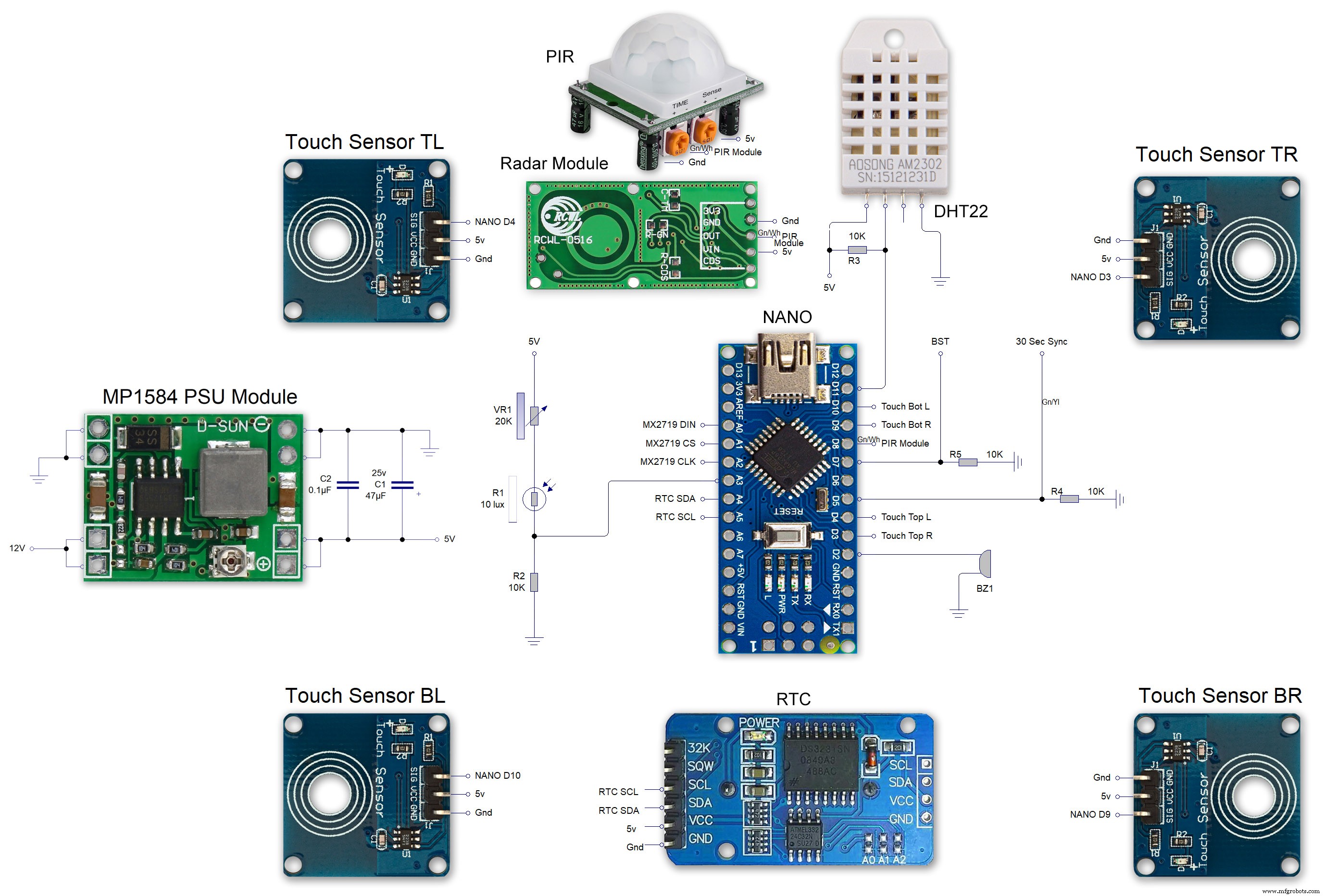 MAX7219 7 segment display module 01 LED connections
 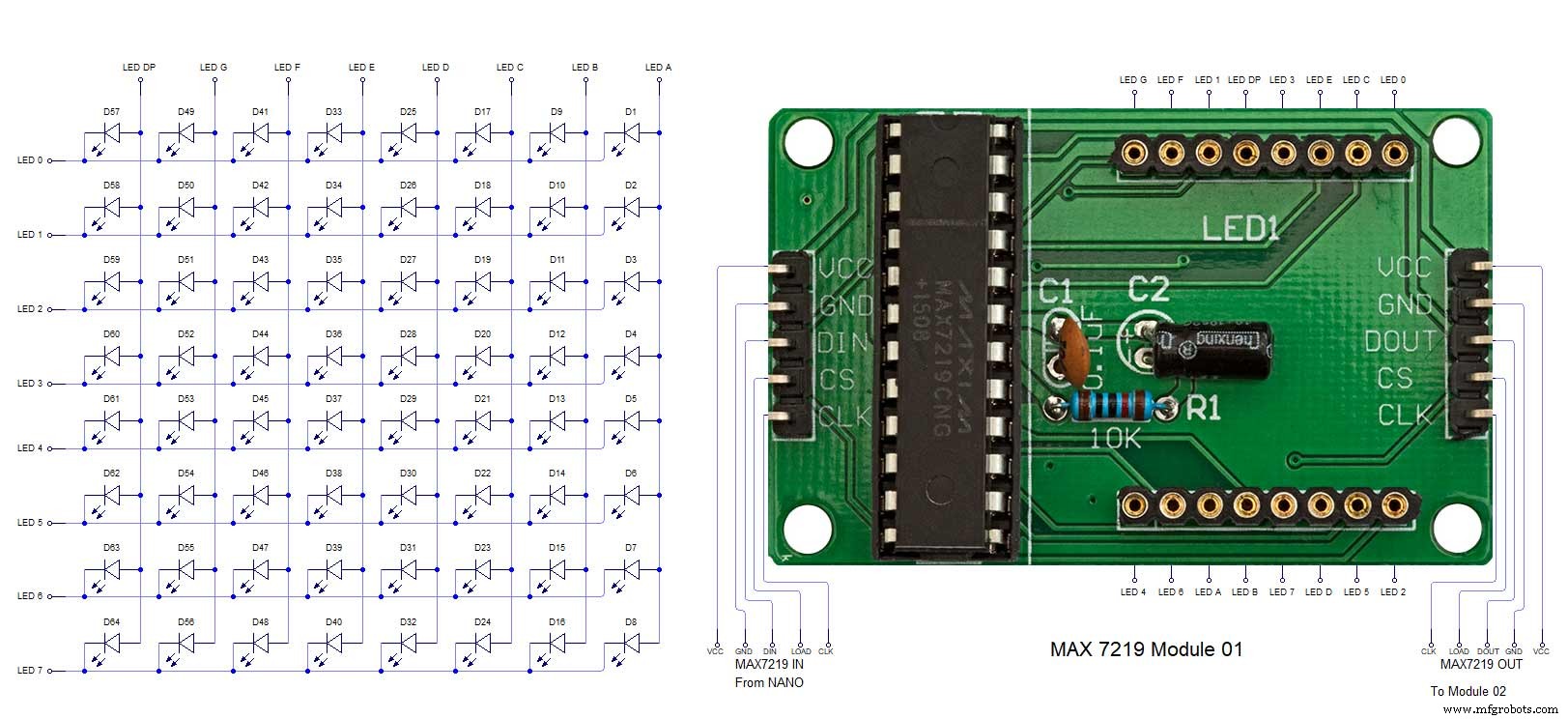 MAX7219 7 segment display module 02 LED connections
 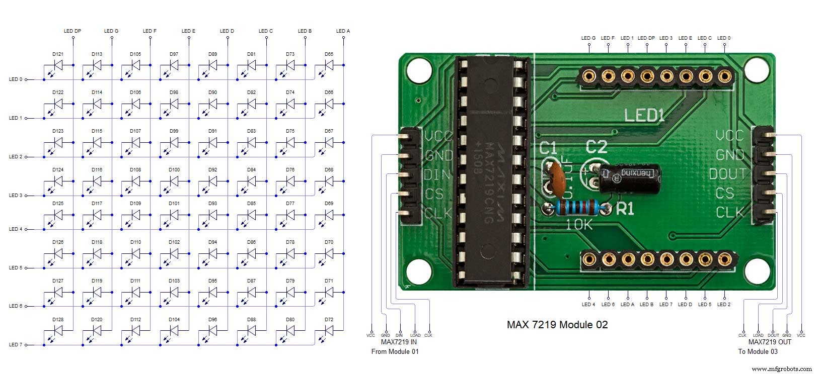 MAX7219 7 segment display module 03 LED connections
 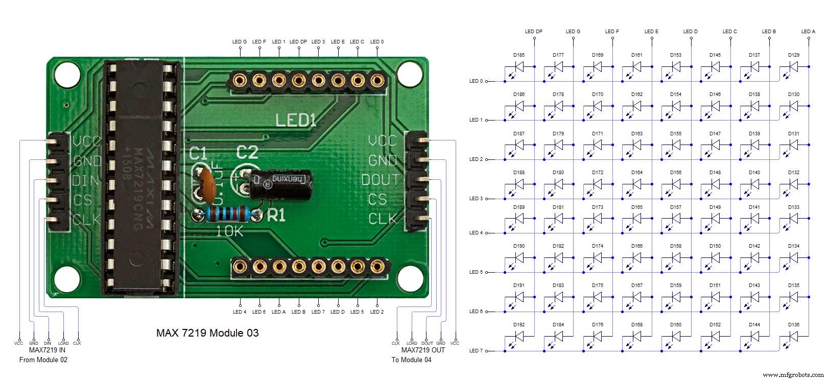 MAX7219 7 segment display module 04 LED connections
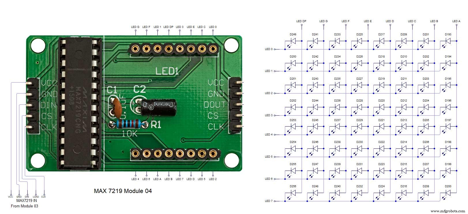
Processo de manufatura
- Relógio de cuco
- Impressão 3D com silicone - está chegando a hora?
- Leitura de sensores analógicos com um pino GPIO
- DIY mais simples relógio IV9 Numitron com Arduino
- Python Timeit() com exemplos
- Simple Word Clock (Arduino)
- Relógio Arduino com horas de oração islâmica
- Reduza gargalos com 5 ferramentas fáceis
- Arduino Temp. Monitor e relógio em tempo real com tela 3.2
- Despertador simples com DS1302 RTC