


O Companion IC
Componentes e suprimentos
 |
| × | 1 | |||
 |
| × | 1 | |||
 |
| × | 4 | |||
 |
| × | 1 | |||
 |
| × | 2 | |||
 |
| × | 3 | |||
 |
| × | 4 | |||
 |
| × | 2 | |||
 |
| × | 1 | |||
 |
| × | 1 |
Ferramentas e máquinas necessárias
 |
| |||
 |
|
Sobre este projeto
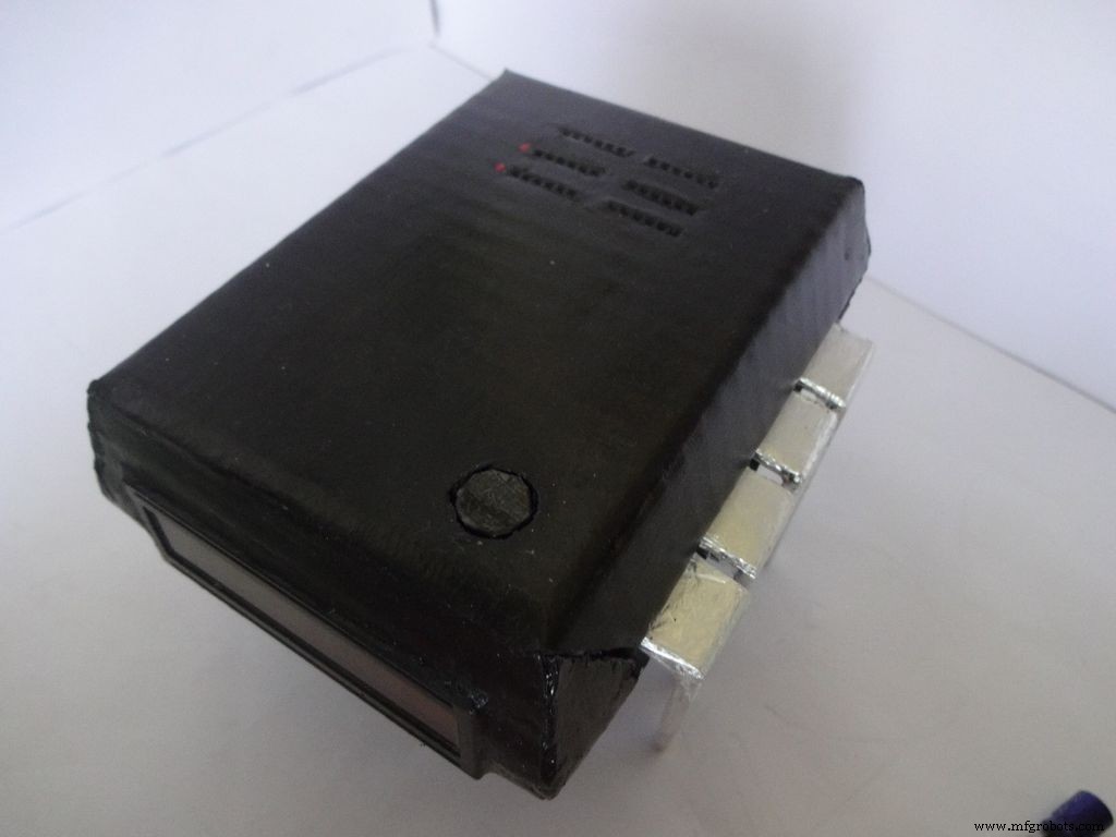

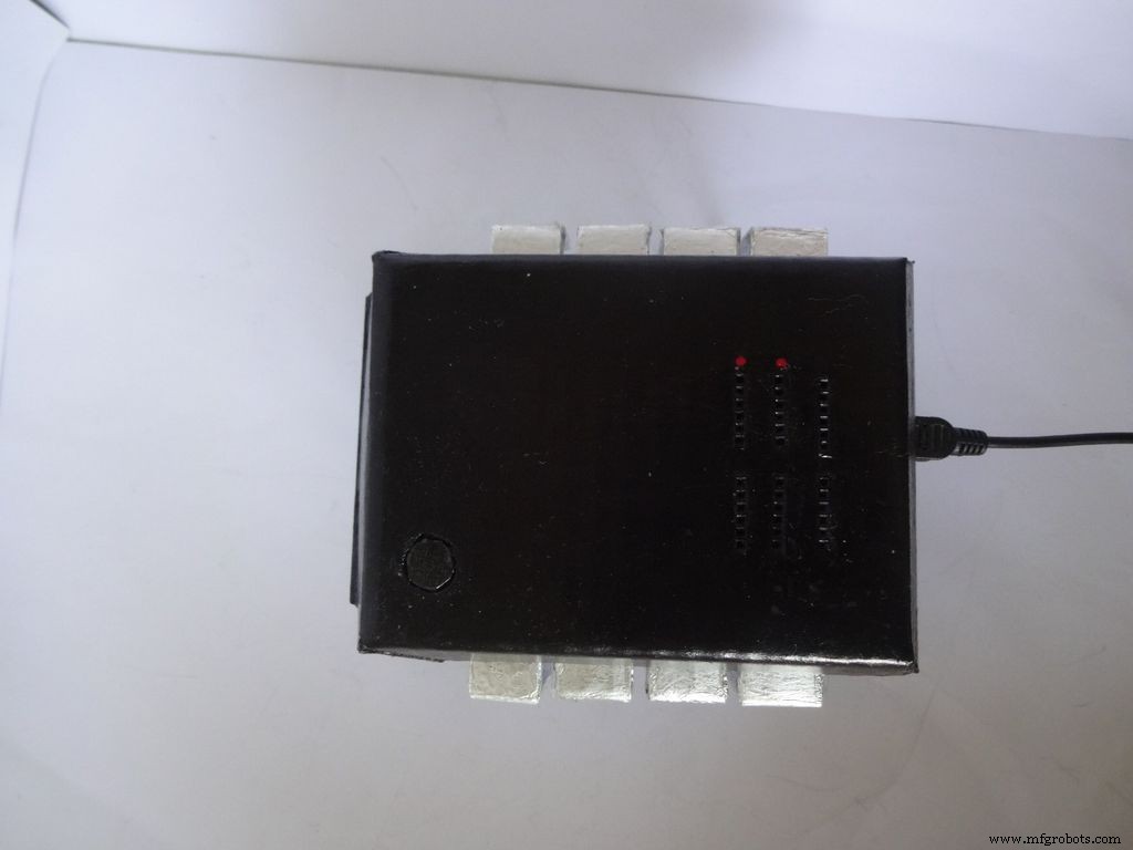
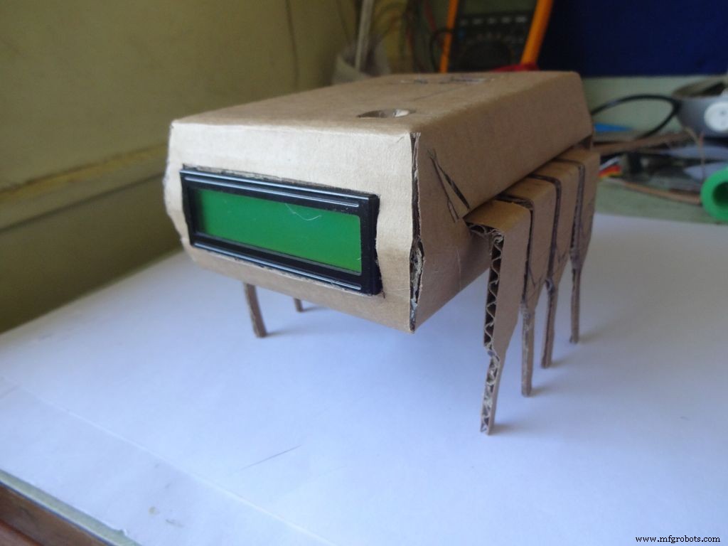
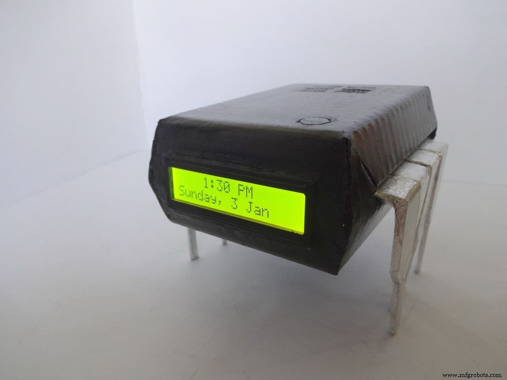
O Companion IC é um relógio + ohmímetro + medidor de capacitância + testador de diodo de aparência muito legal! Ligue-o pressionando o pino 1 do IC! Mantenha-o em sua bancada de trabalho para um teste rápido dos componentes e verificação do tempo. Pode funcionar com baterias ou com USB se você tiver um suprimento perto de sua bancada de trabalho.
Sempre quis publicar um projeto, mas nunca encontrei nada único para fazer até agora! A ideia surgiu quando eu queria testar alguns capacitores para ver se eles estavam com defeito ou não. Eu só tinha um multímetro disponível e ele não tinha uma função de medição de capacitância. Depois de pesquisar sobre isso, descobri que o Arduino pode fazer isso. Decidi que vou fazer um, mas ver os pinos não usados no Arduino não foi muito satisfatório, então decidi adicionar um ohmímetro de escala automática, testador de LED / Diodo rápido e relógio RTC também! Eu também queria medir diretamente os valores, conectando o componente e não usando nenhuma ponta de prova. O design tinha que ser único, então, após um brainstorming, o design do IC foi feito!
Editar (01/07/2016):Teste de continuidade opcional foi adicionado, consulte a seção de comentários.
Este artigo explica detalhadamente como fiz isso e como você também pode fazer por conta própria. É amigável para iniciantes e qualquer pessoa com 2 a 3 semanas de experiência em Arduino / Eletrônica pode construí-lo!
O design é modificável e você pode remover / adicionar novos recursos de acordo com seus requisitos. Fiz a caixa com papelão, mas se você tiver habilidade, pode fazer em madeira ou imprimir em 3D.
Tentei tirar e anexar fotos em cada etapa que fiz (muitas em cada etapa!). A maioria delas foi tirada várias vezes até que eu obtivesse o melhor ângulo / luz, mas ainda algumas delas estão um pouco borradas, pois segurar tudo com as duas mãos às vezes é difícil.
Eu quebrei todo o código e a fiação em partes e etapas, exatamente como o fiz. O código incluído é fortemente comentado e devidamente indentado. À medida que avançamos. vamos combinar todo o código e fiação passo a passo para criar o IC final. Isso deve ajudar qualquer pessoa a entendê-lo claramente. Se não, por favor me avise nos comentários.
Mesmo se você decidir não fazer um, experimente em uma placa de ensaio ou pelo menos leia isto uma vez, pois deve haver algum método ou truque ou algo que você possa aprender aqui e será útil para você algum dia (Sério, você nunca sabe quando clica!)
Etapa 1:ferramentas e componentes necessários
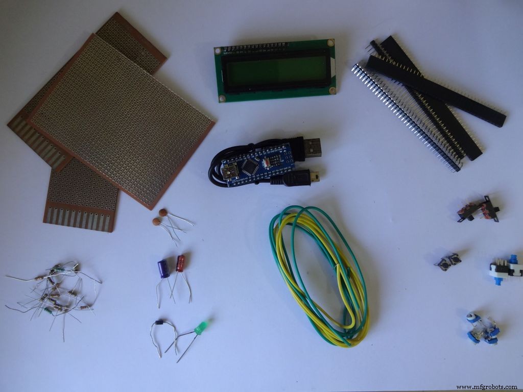

Lista de componentes e materiais usados (links da loja apenas para referência):
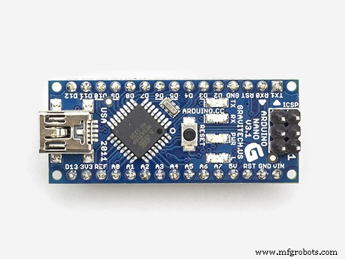
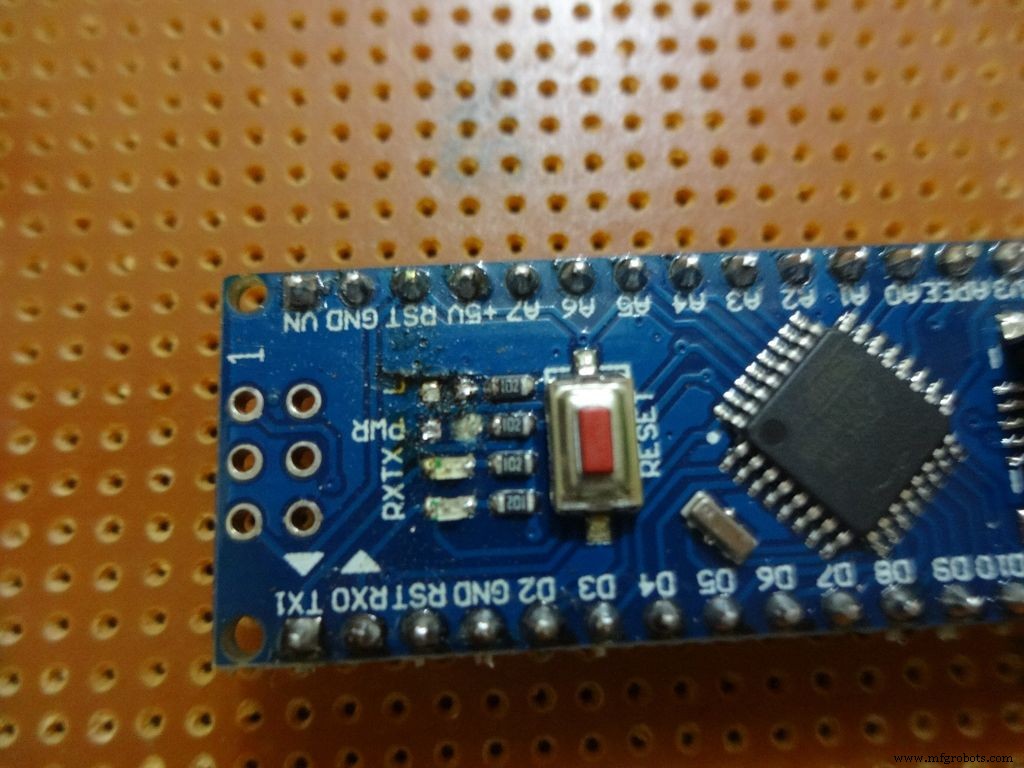
- 1x Arduino Nano V3, Usei um clone com CH340G - ebay
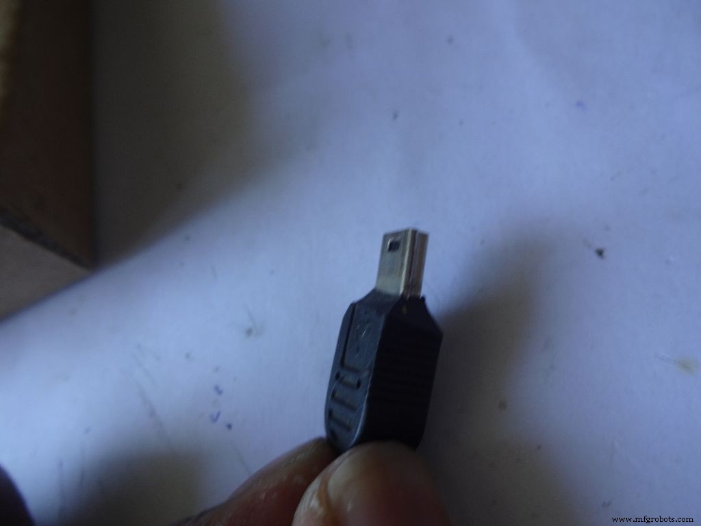
- Mini cabo USB para Arduino Nano - Mini não Micro !
- Cardboard - Usei uma caixa de embalagem, com espessura de ~ 2 mm. Pergunte ao seu vizinho, amigos, vá catar, se não conseguir encontrar um.
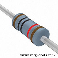
- 4x resistor de 10k ohm - facilmente disponível
- 2x resistor de 220 ohms - facilmente disponível
- 1x (1k, 4,7k, 47k, 100k) resistores ohm - facilmente disponível
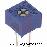
- 1x pequeno potenciômetro de 10k ohm, para controle de contraste do LCD ... qualquer tamanho pequeno funcionará .-- ebay
- 2x Micro botão, para redefinir e botão de mudança de modo, aqueles comuns que você usa em uma placa de ensaio.
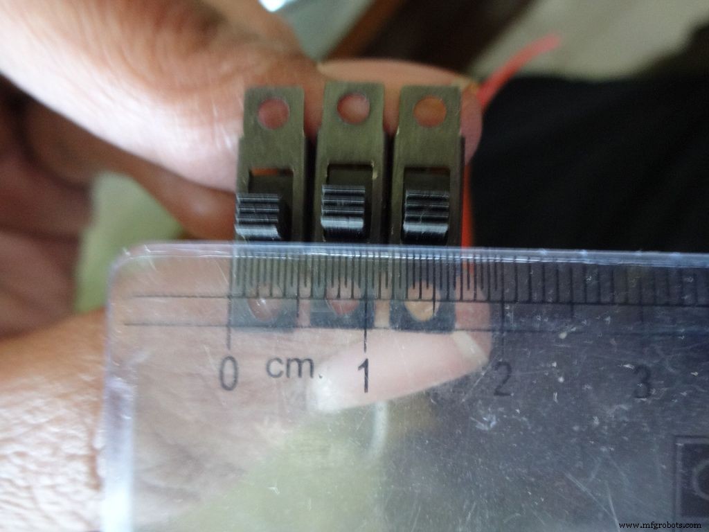
- 3x pequenos interruptores deslizantes , para habilitar a luz de fundo, pinos 0 e 1, esses pinos precisam ser desabilitados durante o uso de Serial - ebay
- 1x Mantido / Alternado / Interruptor de pressão com trava, para interruptor de energia - ebay
- Alguns capacitores, diodos, leds apenas para teste, você vai usá-los algum dia de qualquer maneira.
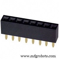
- 4x Tira de alfinetes do cabeçalho feminino - ebay (40 pinos por tira)
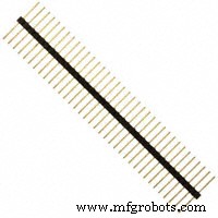
- 2x Tira de alfinetes do cabeçalho macho - ebay (40 pinos por tira)
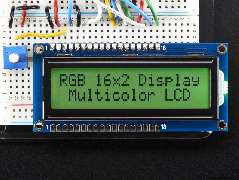
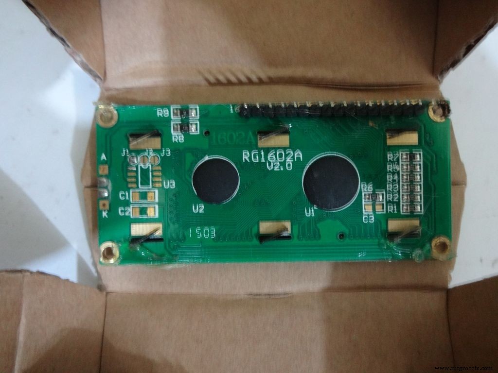
- 1x LCD de 16x2 caracteres - ebay
- 1x DS3231 ou DS1307 Módulo RTC (RTC significa Real Time Clock) - Não compre barato no ebay. Eles usam chips falsos e são imprecisos. Compre isto, isto ou isto. Qualquer um deles funcionará.
- 4x pilhas AA (ou AAA. Usar AAA será muito mais fácil, mas a capacidade da bateria é menor)
- 1x porta-pilhas 4 AA (ou AAA) , variante plana - ebay
- Cabo de fio simples , os usados para placas de ensaio, 22 calibres
- Cabo fita (ou alguns fios finos de par trançado podem ser usados) - ebay
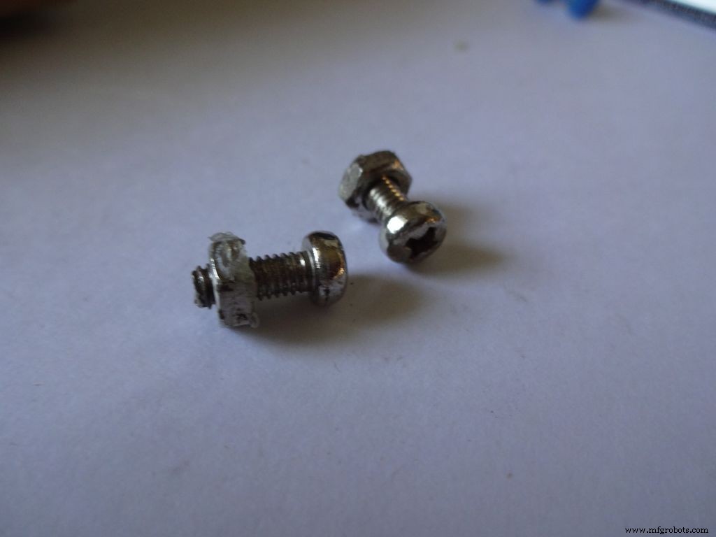
- 2x Porca e parafuso pequenos - Usei os do meu antigo conjunto Meccano (os parafusos têm 1,3 cm de comprimento)
- Tinta acrílica preta e pincéis
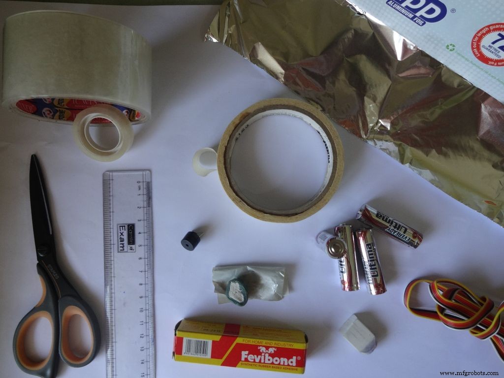
Ferramentas necessárias:
- Ferro de soldar
- Solda
- Desoldering pavio / trança (para quando você bagunçar tudo!)
- Pistola de cola
- Fita adesiva
- Fita para violoncelo, transparente
- Decapador de fio, pinça
- Cortador de caixa afiada
- Uma tesoura afiada
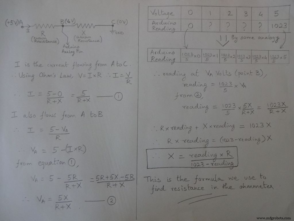
Etapa 2:Ohmímetro - Conceito
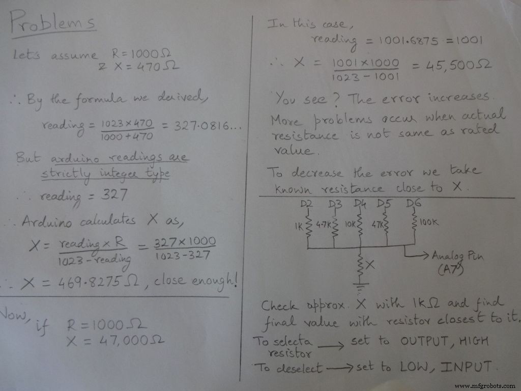
A ideia básica de medir a resistência vem do divisor de tensão.
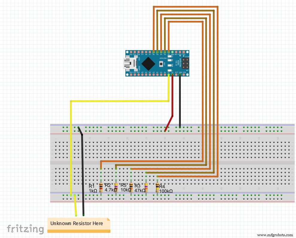
Os valores do resistor são modificáveis, altere os valores de r1, r2, etc. Defina também as faixas (para faixa automática) de acordo. Veja o código abaixo, faça o download dos arquivos nas extremidades e teste o ohmímetro em uma placa de ensaio
Se você está configurando o Nano pela primeira vez, o driver CH340G do pode ser baixado aqui, funciona com windows 7, 8, 8.1 e 10. Usuários de Mac verificam aqui.
Selecione "Arduino Nano" no menu de placas e a porta COM correta. Envio!
Código
// Pino analógico usado para encontrar a resistênciaint Apin =7; // valores de r1 a r5float r1 =1000; float r2 =4700; float r3 =10000; float r4 =47000; float r5 =100000; / / pinos de r1 a r5int r1_pin =2; int r2_pin =3; int r3_pin =4; int r4_pin =5; int r5_pin =6; leitura flutuante =0; // ler do pino analógico e armazenar aqui o flutuador R =0; // calcula desconhecido e armazena hereString finalR; // valor final a ser exibido junto com unitsint caseno; // para depuração, armazena o número do caso // dividimos todo o intervalo em casos e atribuímos um número a cada um, total de 5 casos // caso1:menos de 2850 // caso2:2850 a 7350 // caso3:7350 a 28500 // case4:28500 a 73500 // case5:mais de 73500 # include // necessário para converter float em string, tem a função String (float, n). Explicado abaixo.void setup () {Serial.begin (9600);} void loop () {// primeiro encontramos a resistência desconhecida usando o resistor de 1kOhm // Portanto, desative R2, R3, R4 e R5 digitalWrite (r2_pin, LOW); // gire cada pino para BAIXO antes de defini-lo como INPUT pinMode (r2_pin, INPUT); // girando INPUT quando seu HIGH habilita o resistor pullup interno digitalWrite (r3_pin, LOW); pinMode (r3_pin, INPUT); digitalWrite (r4_pin, LOW); pinMode (r4_pin, INPUT); digitalWrite (r5_pin, LOW); pinMode (r5_pin, INPUT); pinMode (r1_pin, OUTPUT); digitalWrite (r1_pin, HIGH); // lê e calcula a resistência reading =analogRead (Apin); R =(leitura * r1) / (leitura 1023); // se valor <2850, finalR =valor (usando 1kOhm) if (R <2850) {caseno =1; if (R <1000) {// se o valor for menor que 1000 use "Ohm" e não "kOhm" finalR =String (R, 2) + "Ohm"; // String (float, n) Convertendo float em string com n dígitos após decimal // anexar "Ohm" após o valor à string, '+' unir duas strings aqui} else {// use "kOhm R =R / 1000; finalR =String (R, 2) + "kOhm";}} // se o valor estiver entre 2850 e 7350, use o valor obtido por 4,7kOhm else if (R> =2850 &&R <7350) {caseno =2; digitalWrite (r1_pin , LOW); // Ativar apenas 4,7 kOhm pinMode (r1_pin, INPUT); digitalWrite (r3_pin, LOW); pinMode (r3_pin, INPUT); digitalWrite (r4_pin, LOW); pinMode (r4_pin, INPUT); digitalWrite (r5_pin, LOW); ); pinMode (r5_pin, INPUT); pinMode (r2_pin, OUTPUT); digitalWrite (r2_pin, HIGH); leitura =analogRead (Apin); R =(leitura * r2) / (1023-leitura) / 1000; finalR =String ( R, 2) + "kOhm";} // se o valor estiver entre 7350 e 28500, use o valor obtido por 10kOhm else if (R> =7350 &&R <28500) {caseno =3; digitalWrite (r1_pin, LOW); pinMode ( r1_pin, INPUT); digitalWrite (r2_pin, LOW); pinMode (r2_pin, INPUT); digitalWrite (r4_pin, LOW); pinMode (r4_pin, INPUT); digitalWrite (r5_pin, LOW); pinMode (r5_pin, INPUT); ode (r3_pin, OUTPUT); digitalWrite (r3_pin, HIGH); leitura =analogRead (Apin); R =(leitura * r3) / (leitura 1023) / 1000; finalR =cadeia (R, 2) + "kOhm"; } // se o valor estiver entre 28500 e 73500, use o valor obtido por 47kOhm else if (R> =28500 &&R <73500) {caseno =4; digitalWrite (r1_pin, LOW); pinMode (r1_pin, INPUT); digitalWrite (r2_pin, LOW); pinMode (r2_pin, INPUT); digitalWrite (r3_pin, LOW); pinMode (r3_pin, INPUT); digitalWrite (r5_pin, LOW); pinMode (r5_pin, INPUT); pinMode (r4_pin, OUTPUT); digitalWrite (r4_pin, HIGH); leitura =analogRead (Apin); R =(leitura * r4) / (leitura 1023) / 1000; finalR =cadeia (R, 2) + "kOhm"; } // se o valor for maior que 73500, use o valor obtido por 100kOhm else if (R> =73500) {caseno =5; digitalWrite (r1_pin, LOW); pinMode (r1_pin, INPUT); digitalWrite (r2_pin, LOW); pinMode (r2_pin, INPUT); digitalWrite (r3_pin, LOW); pinMode (r3_pin, INPUT); digitalWrite (r4_pin, LOW); pinMode (r4_pin, INPUT); pinMode (r5_pin, OUTPUT); digitalWrite (r5_pin, HIGH); leitura =analogRead (Apin); R =(leitura * r5) / (leitura 1023) / 1000; finalR =cadeia (R, 2) + "kOhm"; } Serial.println (finalR); // imprimindo a string final com unidades Serial.println (""); atraso (1000);}
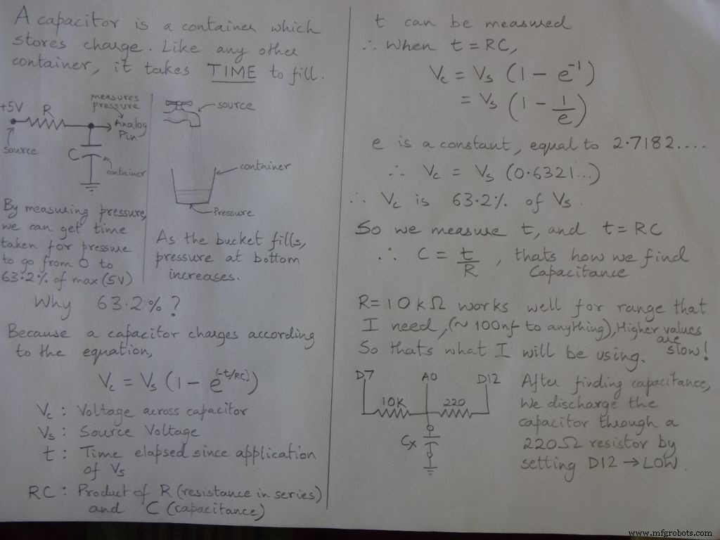
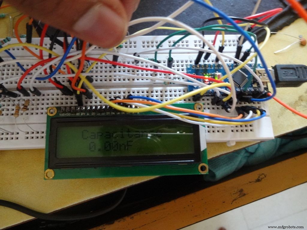
Etapa 3:medidor de capacitância - conceito

Código
/ * RCTiming_capacitance_meter * conceito de código retirado de Paul Badger 2008 * * A tensão do capacitor em uma constante de tempo é definida como 63,2% da tensão de carga. * ou seja, um capacitor é preenchido com 63,2% de sua capacidade total em 1 constante de tempo * / int analogPin =0; // pino analógico para medir a tensão do capacitor int chargePin =7; // pino para carregar o capacitor - conectado a uma extremidade do resistor de carga int descargaPin =12; // pino para descarregar o capacitor, mesmo usado para teste de diodo (chechPin1) float resistorValue =10000.0; // Usamos resistor de 10kOhm unsigned long startTime; unsigned long elapsedTime; float microFarads; // variável de ponto flutuante para preservar a precisão, fazer cálculos float nanoFarads; void setup () {pinMode (chargePin, OUTPUT); // define chargePin para saída digitalWrite (chargePin, LOW); Serial.begin (9600); // inicializa a transmissão serial para depuração} void loop () {digitalWrite (chargePin, HIGH); // define chargePin HIGH e carregamento do capacitor startTime =millis (); while (analogRead (analogPin) <648) {// 647 é 63,2% de 1023, que corresponde à tensão de escala completa} elapsedTime =millis () - startTime; // converte milissegundos em segundos (10 ^ -3) e Farads em microFarads (10 ^ 6), net 10 ^ 3 (1000) microFarads =((float) elapsedTime / resistorValue) * 1000; // (float) converte o tempo decorrido "sem sinal longo" em float Serial.print (elapsedTime); // imprime o valor na porta serial Serial.print ("mS"); // imprime unidades if (microFarads> 1) {Serial.print ((long) microFarads); // imprime o valor na porta serial Serial.println ("microFarads"); // imprime unidades} else {// se o valor for menor que um microFarad, converta para nanoFarads (10 ^ -9 Farad). nanoFarads =microFarads * 1000,0; // multiplique por 1000 para converter em nanoFarads (10 ^ -9 Farads) Serial.print ((long) nanoFarads); // imprime o valor na porta serial Serial.println ("nanoFarads"); // imprime unidades} / * carrega novamente o capacitor * / digitalWrite (chargePin, LOW); // define o pino de carga para BAIXO pinMode (descargaPin, OUTPUT); // define o pino de descarga para saída digitalWrite (descargaPin, LOW); // define o pino de descarga LOW while (analogRead (analogPin)> 0) {// espera até que o capacitor esteja completamente descarregado} pinMode (descargaPin, INPUT); // defina o pino de descarga de volta para input}
Etapa 4:Teste de diodo
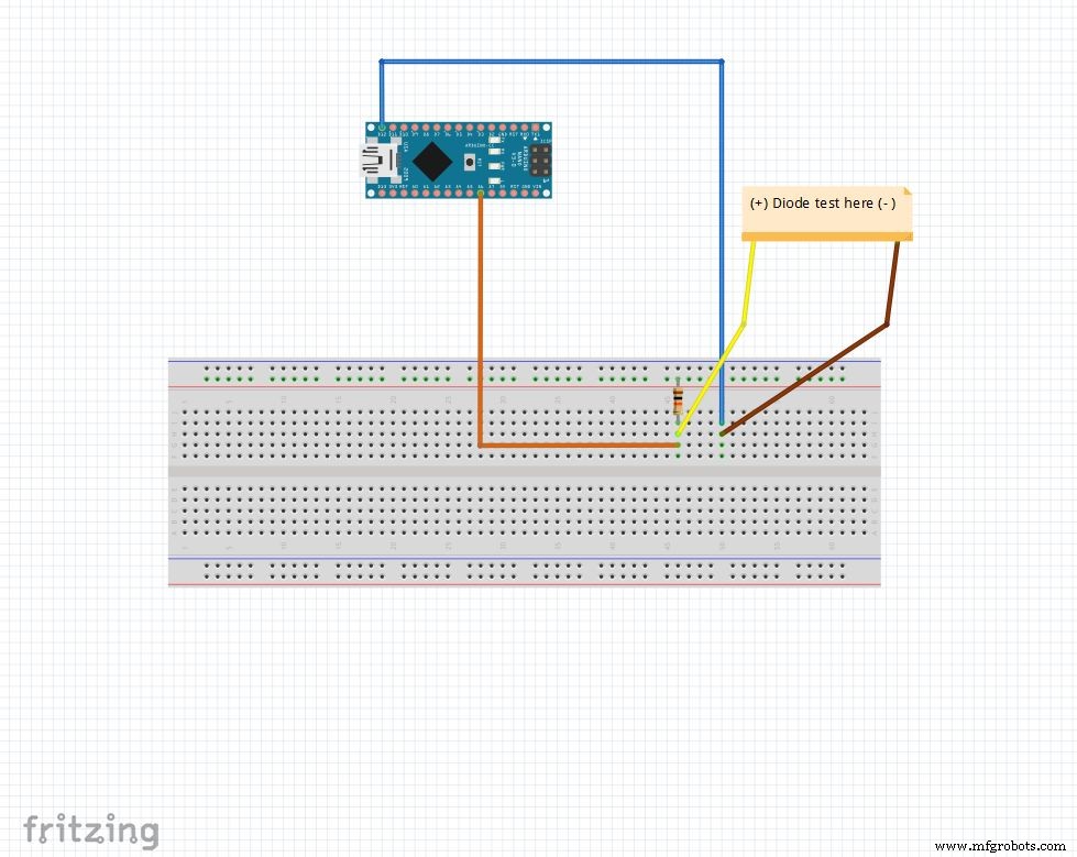
O pino analógico é puxado para 5 V com o resistor de 10k Ohm. Então, o pino analógico lê 1023 quando nada está conectado. D12 está definido para SAÍDA , BAIXO .
Quando um diodo é polarizado direto entre pino analógico ( 5V ) e D12 ( GND ), pino analógico lê 100-400 .
Quando é polarizado reversamente, praticamente uma corrente muito pequena flui e pino analógico lê 900-1023 .
Dessa forma, podemos simplesmente descobrir o lado p e n de qualquer diodo. Isso pode ser usado para verificação rápida de LEDs e diodos.
Código
String state ="nulo"; int checkPin1 =12; int checkPin2 =6; void setup () {Serial.begin (9600);} void loop () {pinMode (checkPin1, OUTPUT); digitalWrite (checkPin1, LOW); // o pino 11 é definido como baixo // a leitura analógica é normalmente puxada pelo resistor de 10k, então a leitura nula é 1023 // Na polarização direta, o pino analógico é conectado a checkPin1, que é BAIXO. Portanto, lendo menos de 1023 // Praticamente uma pequena corrente flui em polarização reversa também, então pegamos 700 para diferenciar if (analogRead (checkPin2) <700) {state ="forward"; } Serial.println (estado); Serial.println (analogRead (checkPin2)); estado ="nulo"; atraso (500);}
Etapa 5:Relógio em tempo real (RTC)
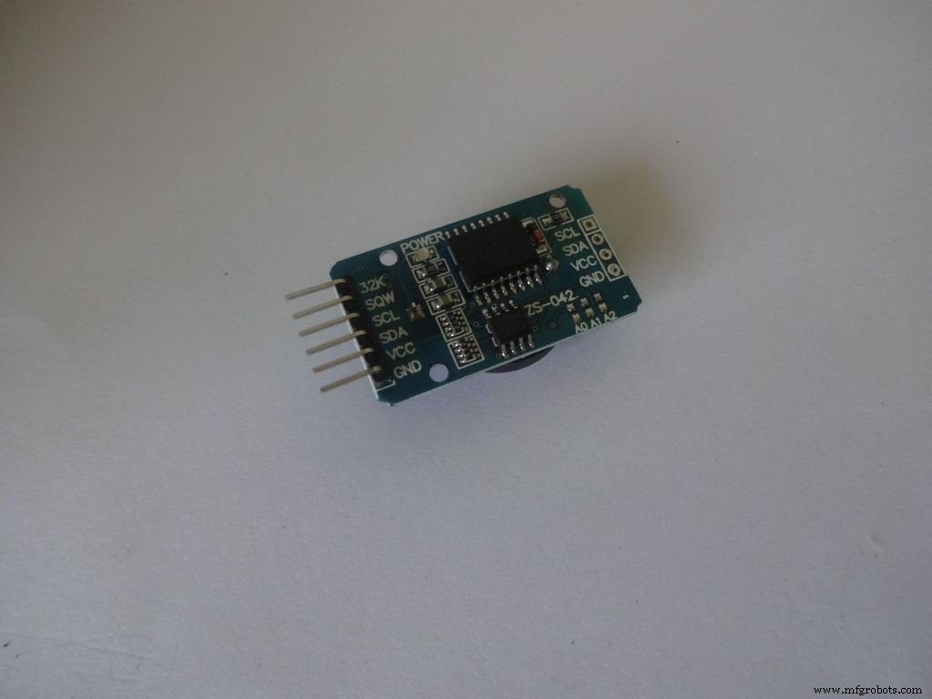
O RTC mantém informações de segundos, minutos, horas, dia, data, mês e ano. Ele continua contando mesmo quando a alimentação externa é removida, graças à pequena célula tipo moeda nele. A data no final do mês é ajustada automaticamente para meses com menos de 31 dias, incluindo correções para ano bissexto.
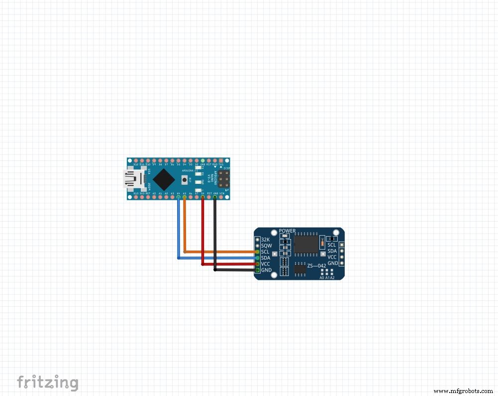
Seja qual for o módulo que você tiver, usaremos 4 pinos: Vcc , GND , SDA e SCL . O SDA e SCL pinos no arduino nano e uno são A4 e A5 respectivamente. Para outros arduinos, pesquise no Google!
Estaremos utilizando a biblioteca "RTClib", que torna a configuração e o acesso aos horários super fáceis! A biblioteca pode ser baixada aqui (Clique em "Download ZIP" e extraia o "RTClib-master" na pasta de bibliotecas do Arduino. Mais sobre como instalar bibliotecas.)
Para definir a hora, baixe o "RTC_set_time.ino" anexado a esta etapa e descomente as linhas,
rtc.adjust (DateTime (F (__ DATE__), F (__ TIME__))); Se você quiser usar o tempo definido no seu computador durante a compilação. Ou
rtc.adjust (DateTime (2014, 1, 21, 3, 0, 0)); // ano, mês, data, hora, minuto, segundos Para definir uma hora personalizada.
Conecte como mostrado e faça o upload. Abra Serial monitorar em 9600 baud para ver a hora atual. Verifique novamente após algumas horas para ver como o RTC está se recuperando.
Certifique-se de recomendar essas linhas e carregue novamente após definir a hora uma vez. Do contrário, você continuará redefinindo-o cada vez que o Arduino redefinir!
Código
// Funções de data e hora usando um RTC DS1307 conectado via I2C e Wire lib # include #include RTC_DS1307 rtc; // criando objeto "rtc" de RTC_DS1307, objetos são usados para acessar funções // mais em objetos e classes:https://www.youtube.com/watch?v=ABRP_5RYhqUchar daysOfTheWeek [7] [12] ={"Sunday", "Monday", "Tuesday", " Quarta-feira "," quinta-feira "," sexta-feira "," sábado "}; configuração nula () {Serial.begin (9600); rtc.begin (); // a linha seguinte define o RTC para a data e hora em que este esboço foi compilado // rtc.adjust (DateTime (F (__ DATE__), F (__ TIME__))); // Esta linha define o RTC com uma data e hora explícitas, por exemplo, para definir // 21 de janeiro de 2014 às 3h, você chamaria:// rtc.adjust (DateTime (2014, 1, 21, 3, 0, 0) );} void loop () {DateTime now =rtc.now (); Serial.print (now.year ()); Serial.print ('/'); Serial.print (now.month ()); Serial.print ('/'); Serial.print (now.day ()); Serial.print ("("); Serial.print (daysOfTheWeek [now.dayOfTheWeek ()]); Serial.print (")"); Serial.print (now.hour ()); Serial.print (':'); Serial.print (now.minute ()); Serial.print (':'); Serial.print (now.second ()); Serial.println (); Serial.println (); atraso (1000);}
Etapa 6:configuração final
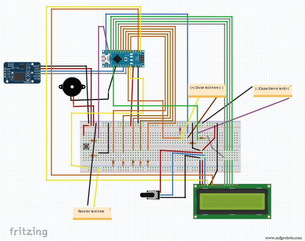
Então esse é o circuito final depois de combinar todos os elementos. O código principal e o arquivo fritzing estão anexados no final.
Baixe o fritzing de fritzing.org se ainda não o fez.
Extraia o arquivo Main_code.rar e abra Main_file_rtc.ino. Incluí todas as declarações de variáveis em definições.h separadas arquivo de cabeçalho, ele será adicionado automaticamente quando você abrir o código principal.
As diferentes partes são transformadas em funções: Clock () , findResistance () , findCapcitance () e diodeTest () . Eles são escritos em guias separadas, tornando a leitura fácil e as alterações são fáceis de implementar. O arquivo principal apenas verifica o estado do "botão de modo" e chama as funções apropriadas.
Outros detalhes são explicados corretamente no próprio código.
Depois de um teste em uma placa de ensaio, estamos prontos para começar a fazer o IC!
Observação:a campainha, se ainda não for utilizada, pode ser utilizada quando necessário, por exemplo, uma função de continuidade.
Etapa 7:Preparando os interruptores
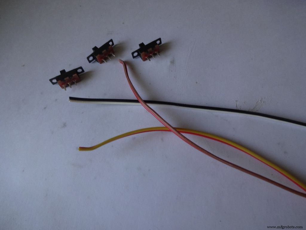
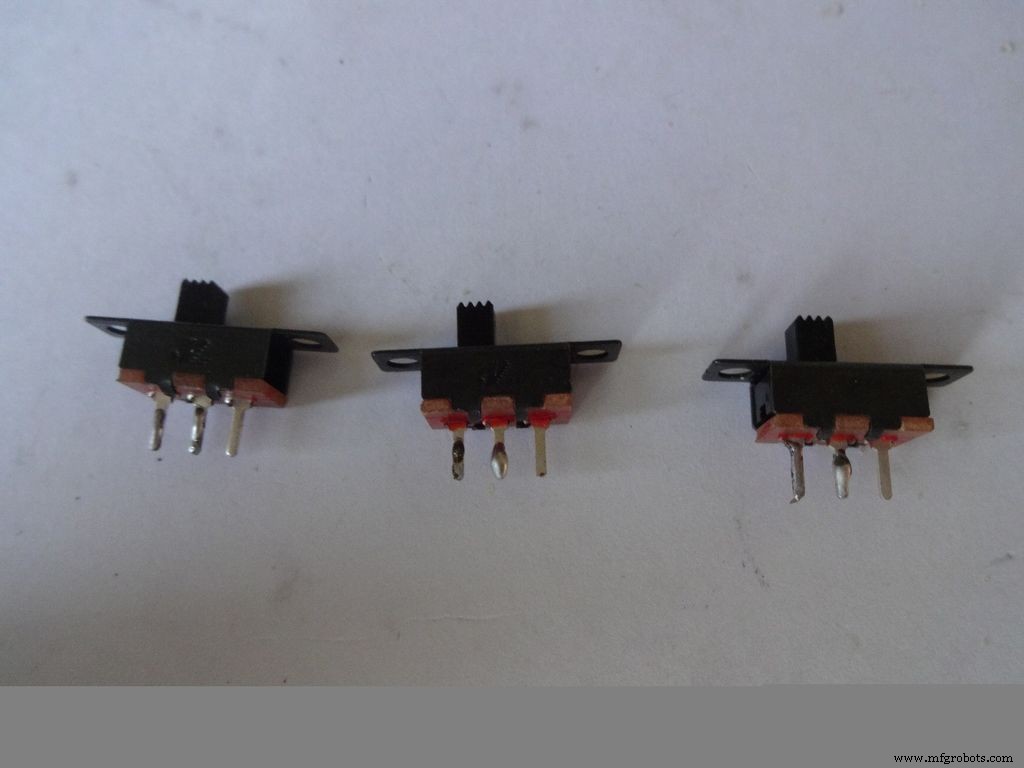


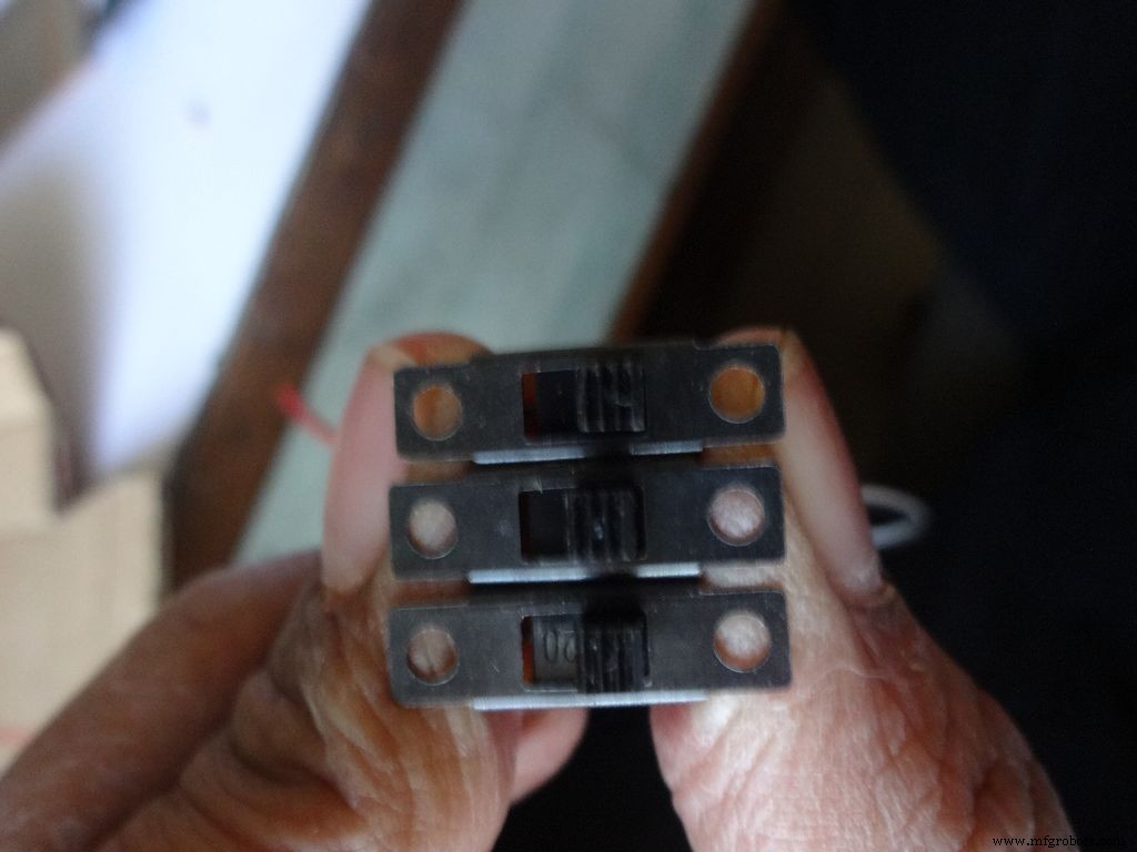
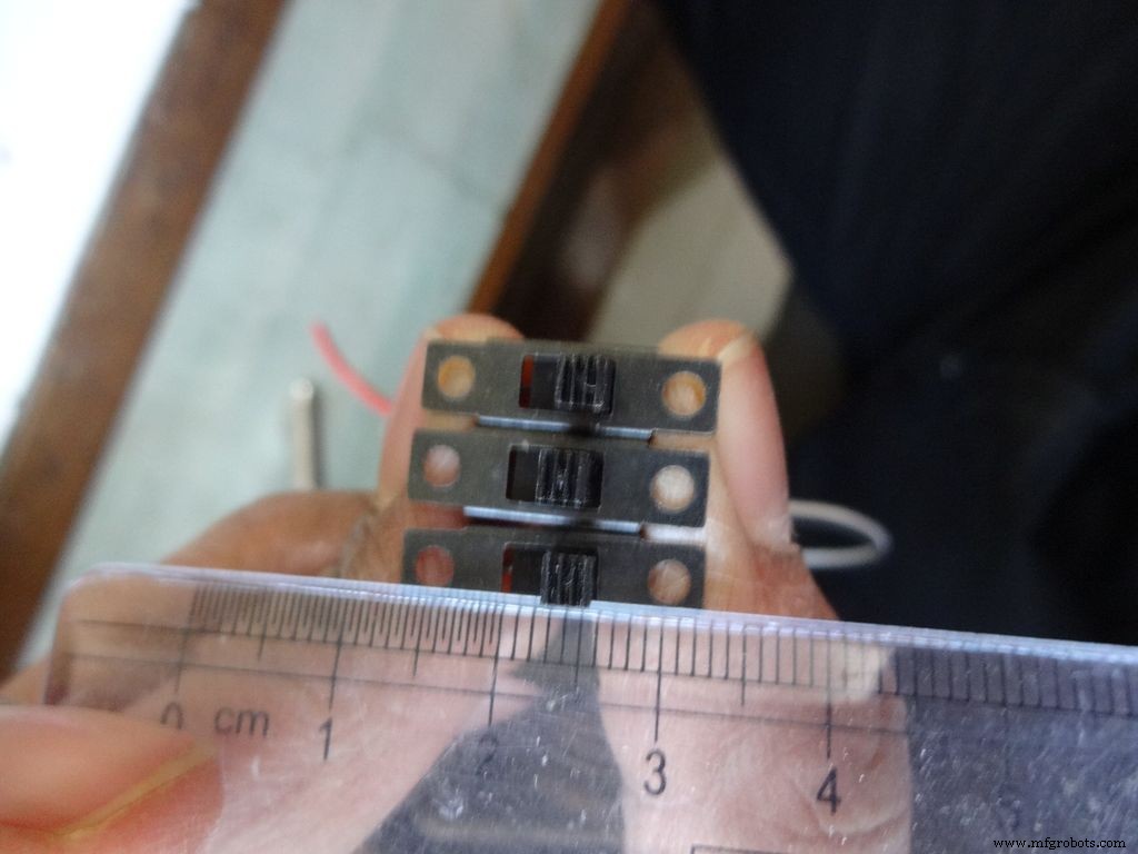
Pegue os 3 interruptores deslizantes junto com 3 pares de fios, com cerca de 10 cm de comprimento. Eu divido o cabo da fita para isso.
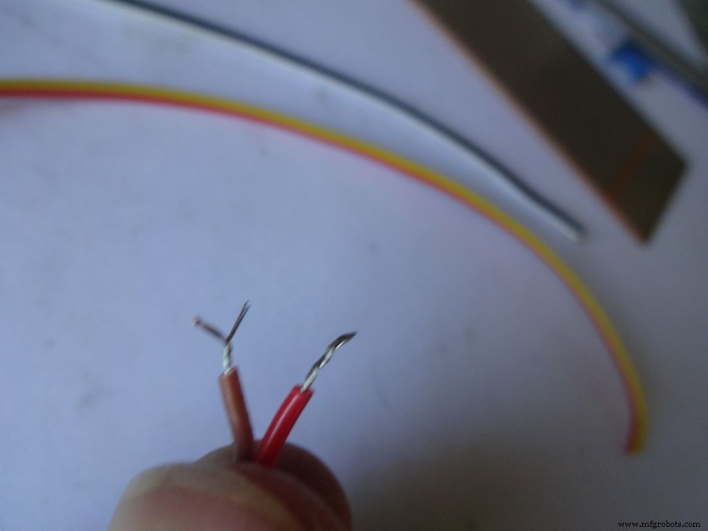
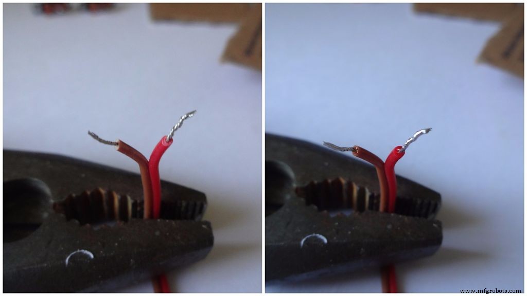
Retire uma pequena parte do isolamento (não mais do que 5 mm) e torça os fios.
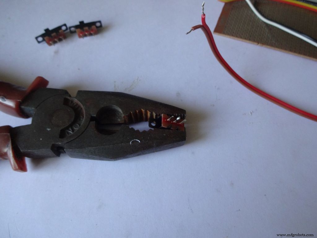
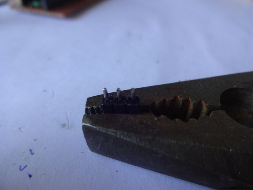
Aplique um pouco de solda em 2 pinos adjacentes de cada uma das chaves. Use algo para segurá-lo no lugar enquanto você solda, usei um alicate pesado.
Se você não soldou antes, agora é um bom momento para começar. O Youtube tem muitos vídeos ensinando como soldar corretamente. As lições do PACE são muito informativas, por favor, assista.
Em seguida, temos que 'estanhar' os fios. Toque a ponta do ferro de solda no fio a ser estanhado. Aplique um pouco de solda entre a ponta e o fio, isso cria uma ponte que conduz o calor da ponta para o fio. Em seguida, você aplica a solda diretamente no fio, no lado oposto da ponta do ferro de solda . Remova a solda. Remova a ponta. Um vídeo sobre isso.
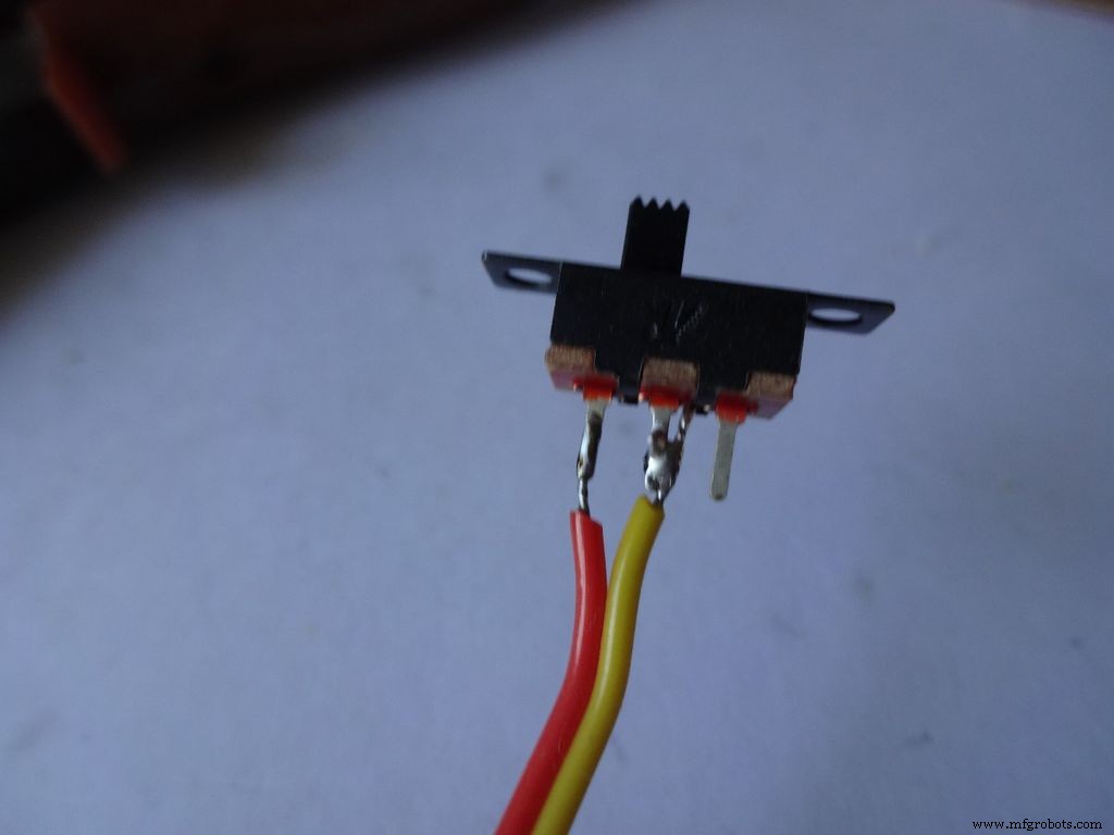
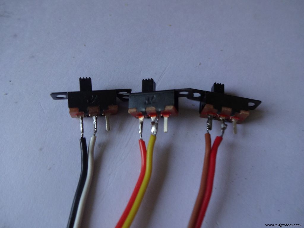
Depois disso, segure a chave no lugar, leve um dos fios estanhados ao pino e reflua a solda tocando o ferro de solda. Faça o mesmo com o segundo fio. Observe que coloquei os fios de cor escura em um lado dos interruptores.
Agora repita o procedimento e conecte dois fios a um botão (este será o botão de reset). Certifique-se de não colocar fios nas extremidades do botão normalmente conectadas.
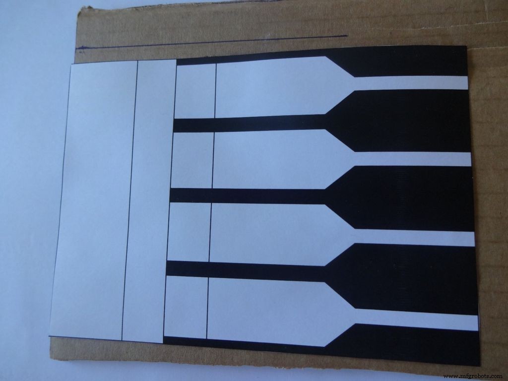
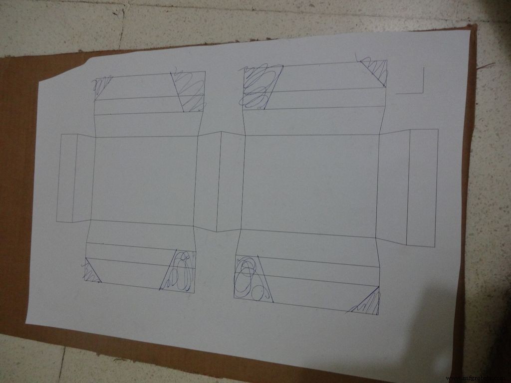
Etapa 8:Fazendo o caso - Cortando o layout
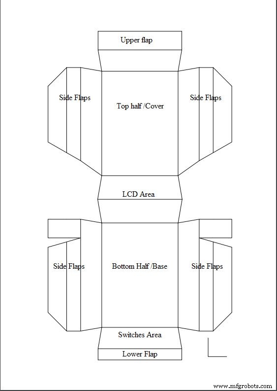
Baixe "Layout_Final_A3.pdf" ou "" Layout_Final_ANSI_B.pdf ", com base no tamanho do papel disponível em sua região. Anexo no final.
Imprima em um papel de tamanho A3 (29,7 x 42,0 cm ou 11,69 x 16,53 polegadas) ou no ANSI B alternativo dos EUA (11 x 17 polegadas ou 279 × 432 mm). Certifique-se de que, ao imprimir, você selecionou o tamanho e a orientação adequados do papel e selecione a opção "Tamanho real". Confirme se a impressão é precisa medindo o pequeno ângulo direito no canto inferior direito, que deve ser de 2 cm x 2 cm.
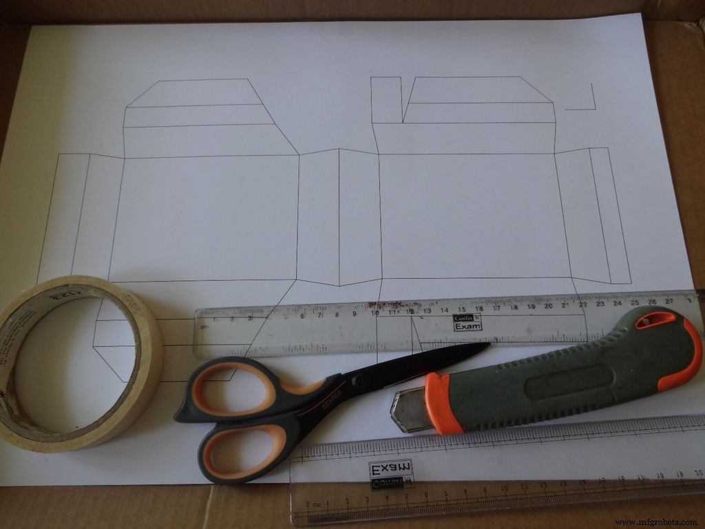
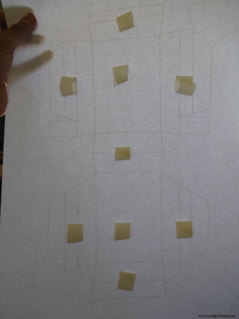
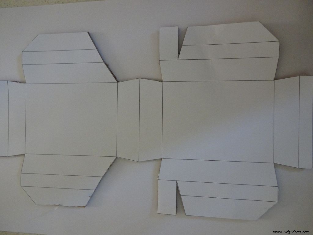
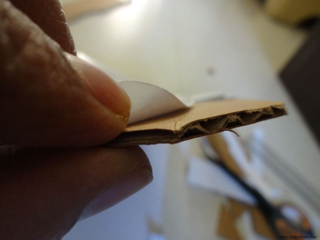
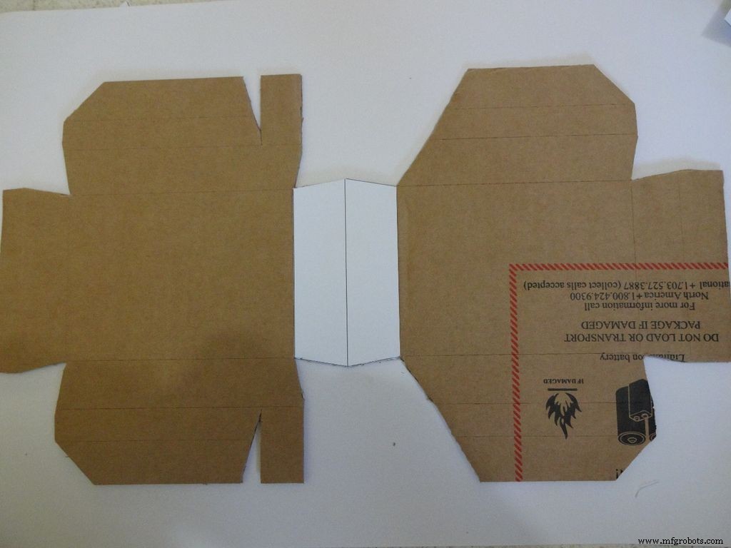
Corte um pedaço de papelão mais ou menos do que o layout. Rasgue um pequeno pedaço de fita, forme um rolo de 'dupla face adesiva' e prenda-o nos locais indicados. Em seguida, cole a folha no papelão.
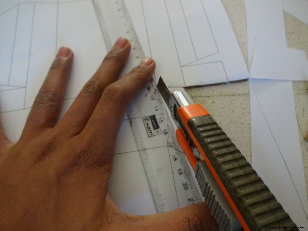
Use uma tesoura afiada ou um cortador de caixa com uma régua para cortar o limite externo do layout da caixa. Achei cortadores de caixa muito melhores do que tesouras. A maioria dos cortadores tem lâminas que podem ser quebradas em estágios para obter uma ponta nova e afiada, portanto, é recomendável fazer isso. Mantenha outro pedaço de papelão ou madeira embaixo da parte que você está cortando, isso ajuda a obter cortes mais limpos.
Além disso, não manter a régua corretamente na linha durante o corte é um erro comum. Não faça isso com pressa.
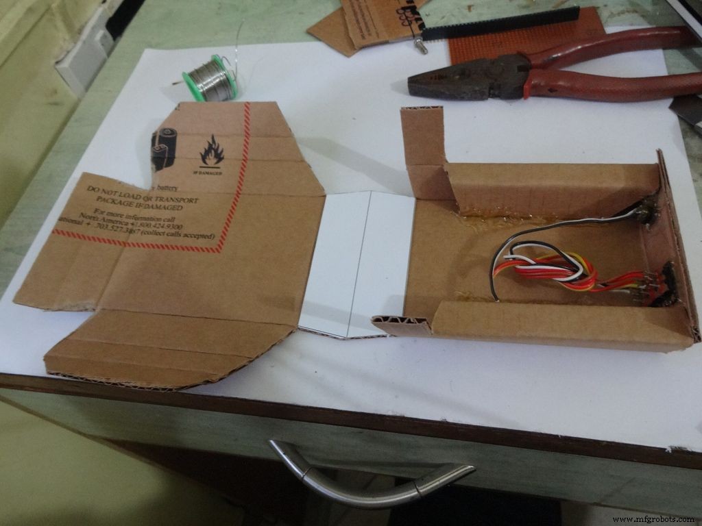
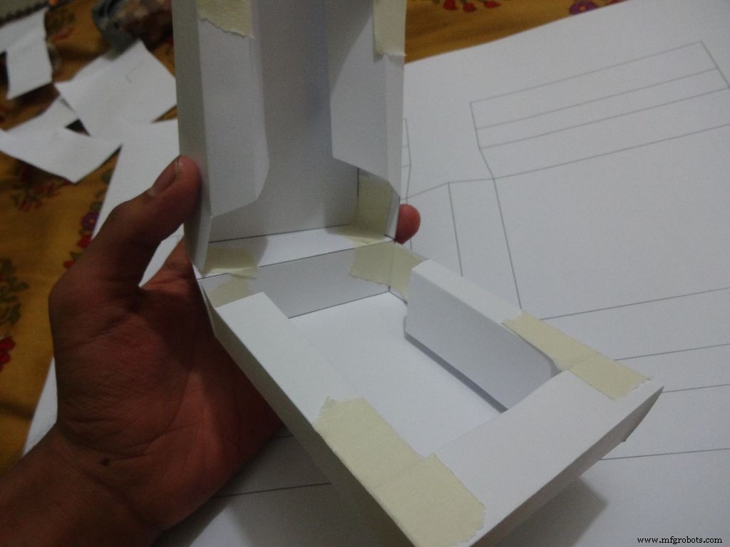
Etapa 9:Construindo a Caixa - Enrugando e Dobrando
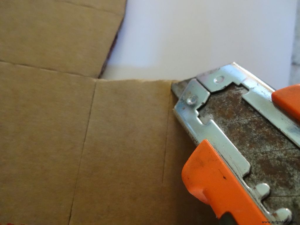
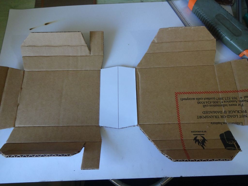


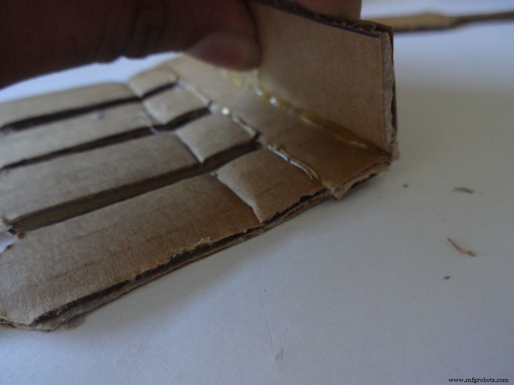
Usando o cortador com a escala, cuidadosamente faça vincos ao longo de todas as linhas de dobra, exceto a linha do meio na área do LCD. Dobre e dobre todas as partes dobráveis e retifique quaisquer vincos incompletos.
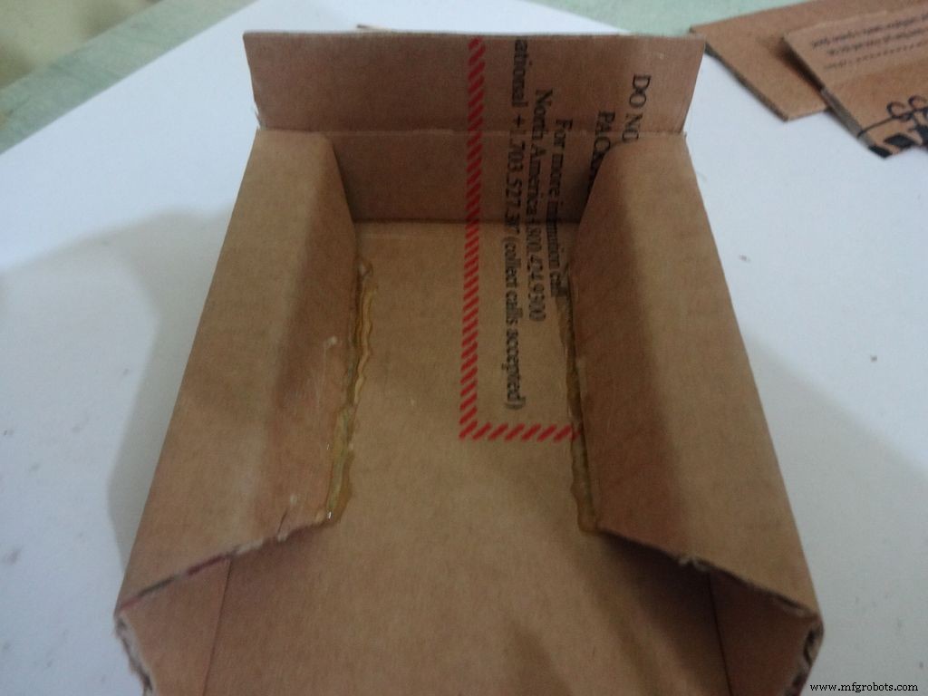
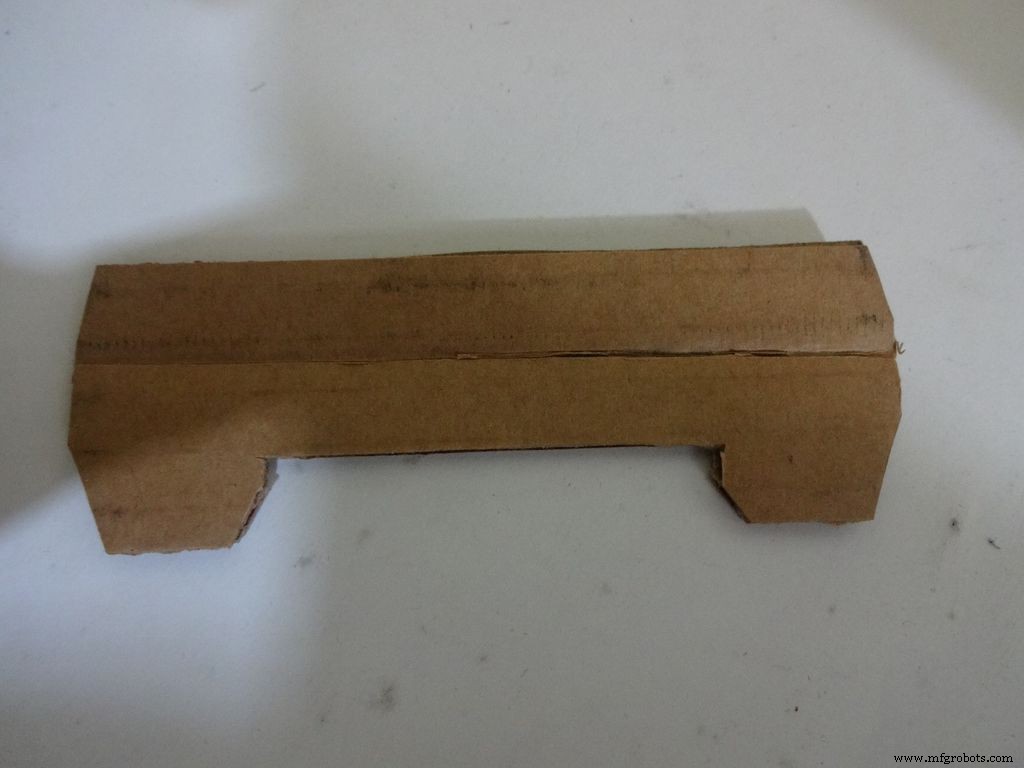
Para a metade inferior ou base:
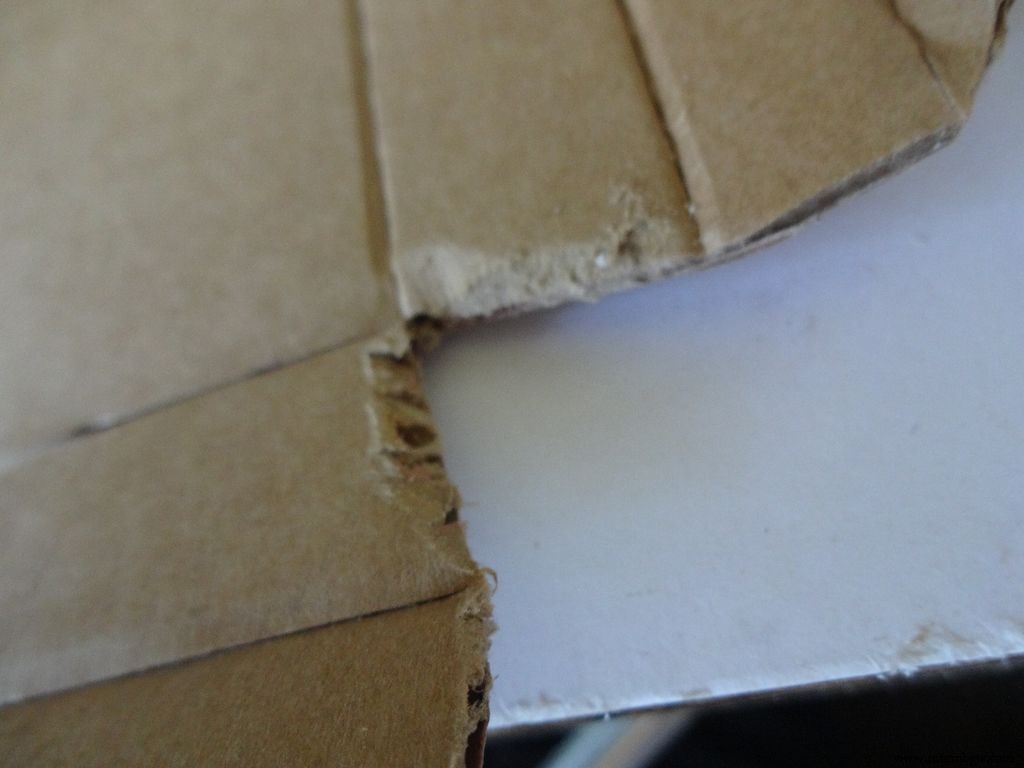
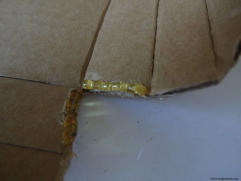
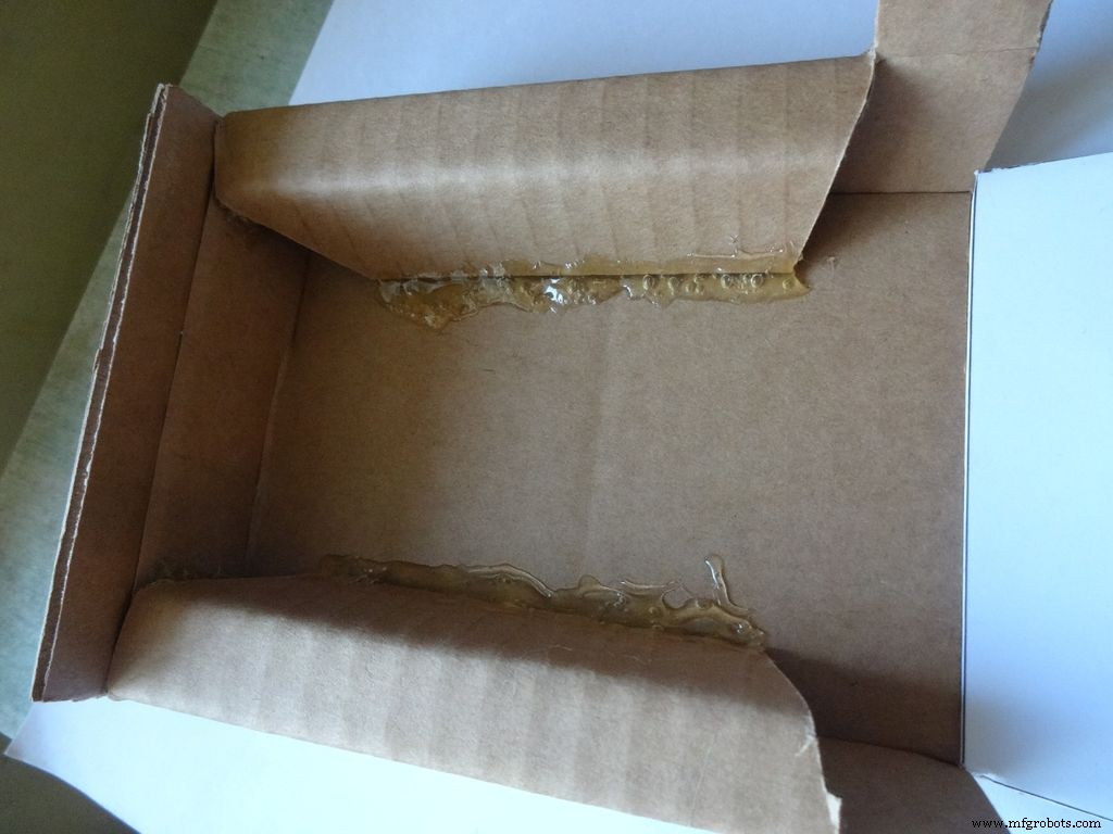
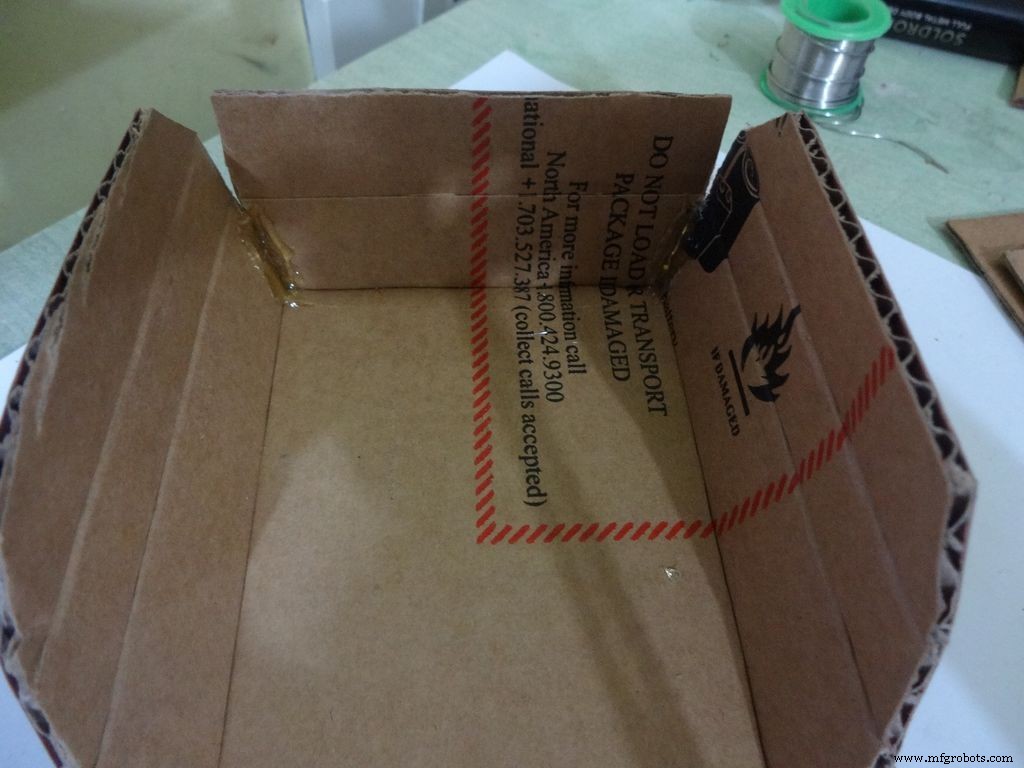
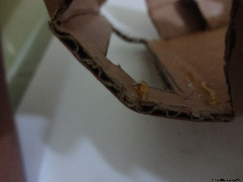
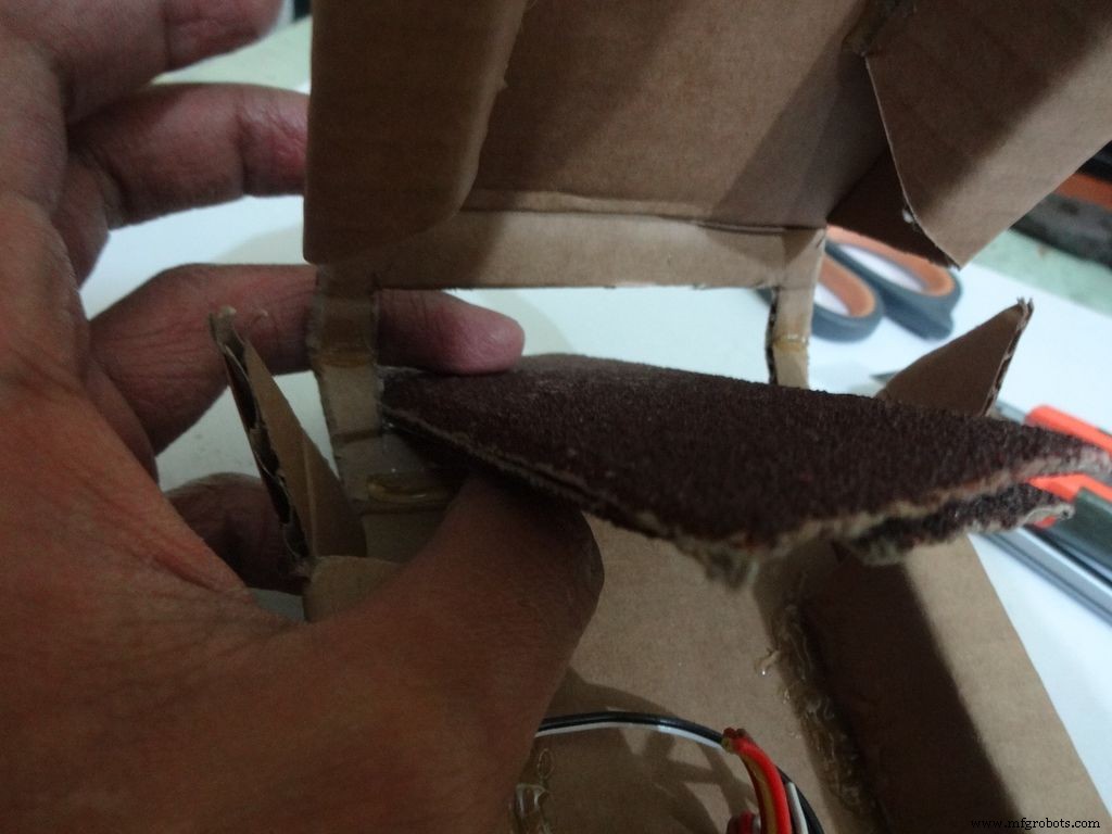
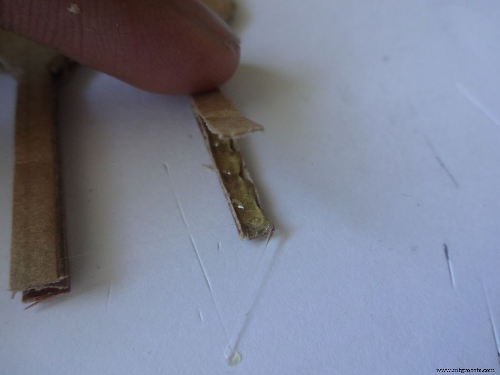
Usando a lixa, lixe as primeiras quatro bordas em declive, aplique cola quente com uma pistola de cola (um lado de cada vez), junte e segure por 30-60 segundos enquanto a cola esfria.
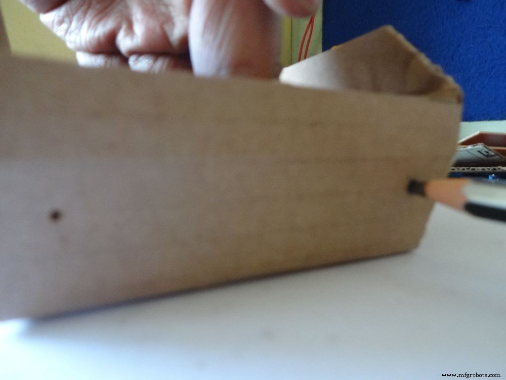
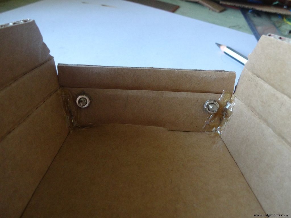
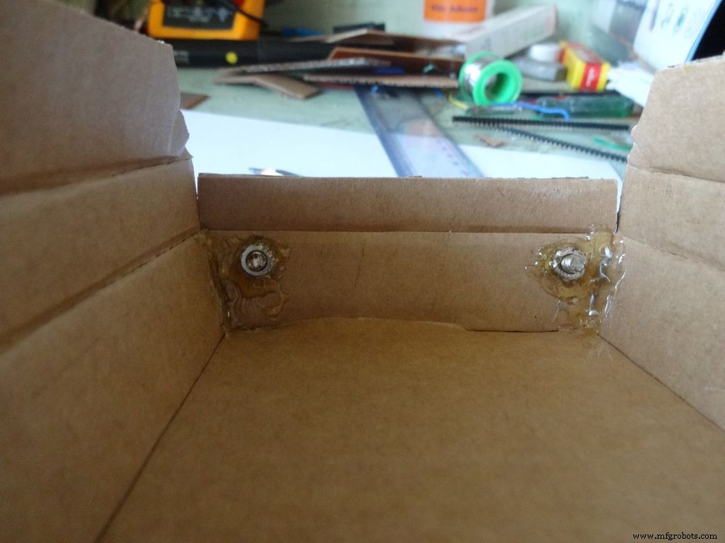
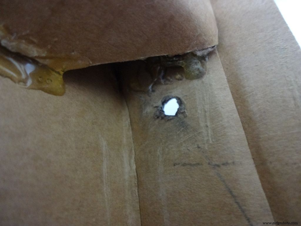
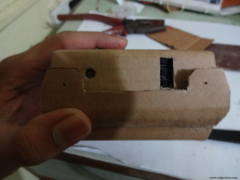
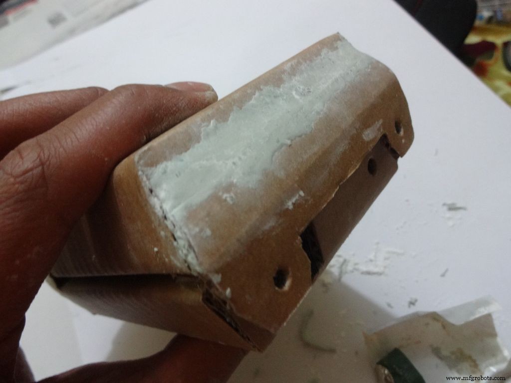
Faça dois furos com um alfinete como mostrado e aumente com um lápis apenas o suficiente para encaixar o parafuso. Aperte a porca por dentro, aplique cola quente (só na porca!), Deixe esfriar. Remova o parafuso com um scredriver.
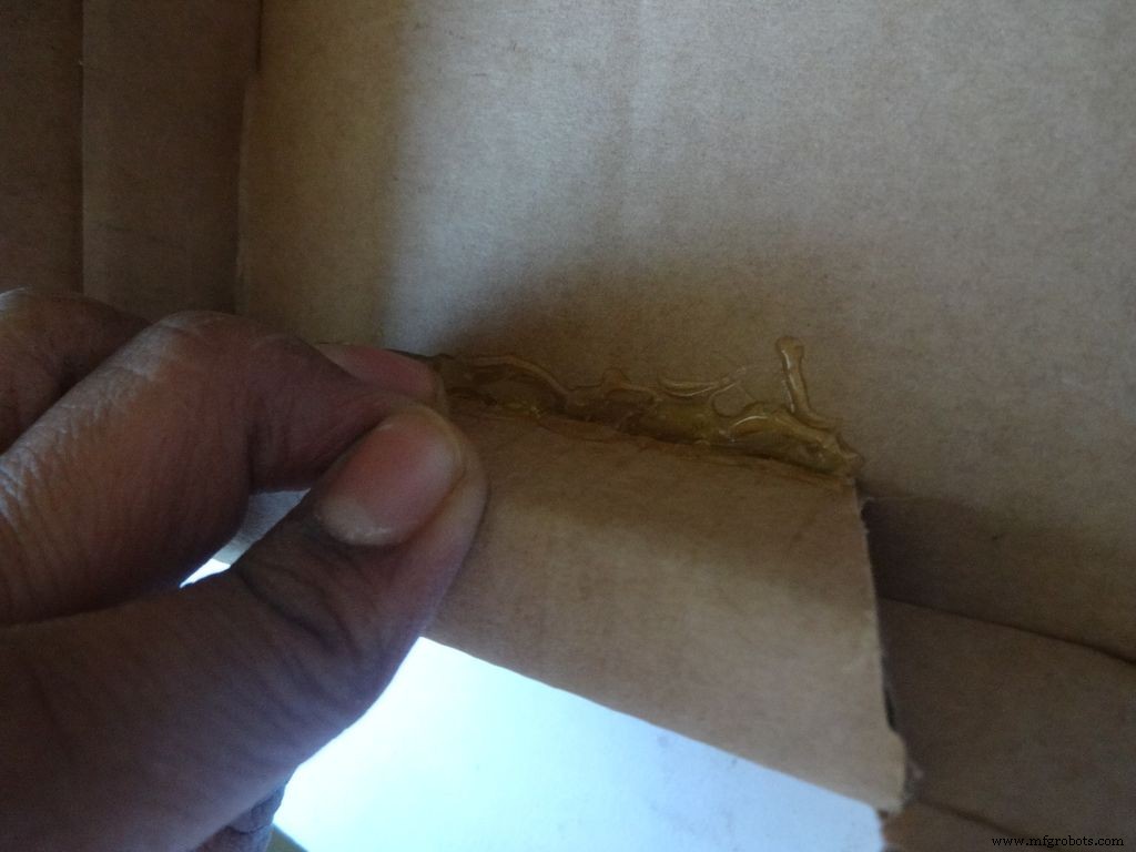
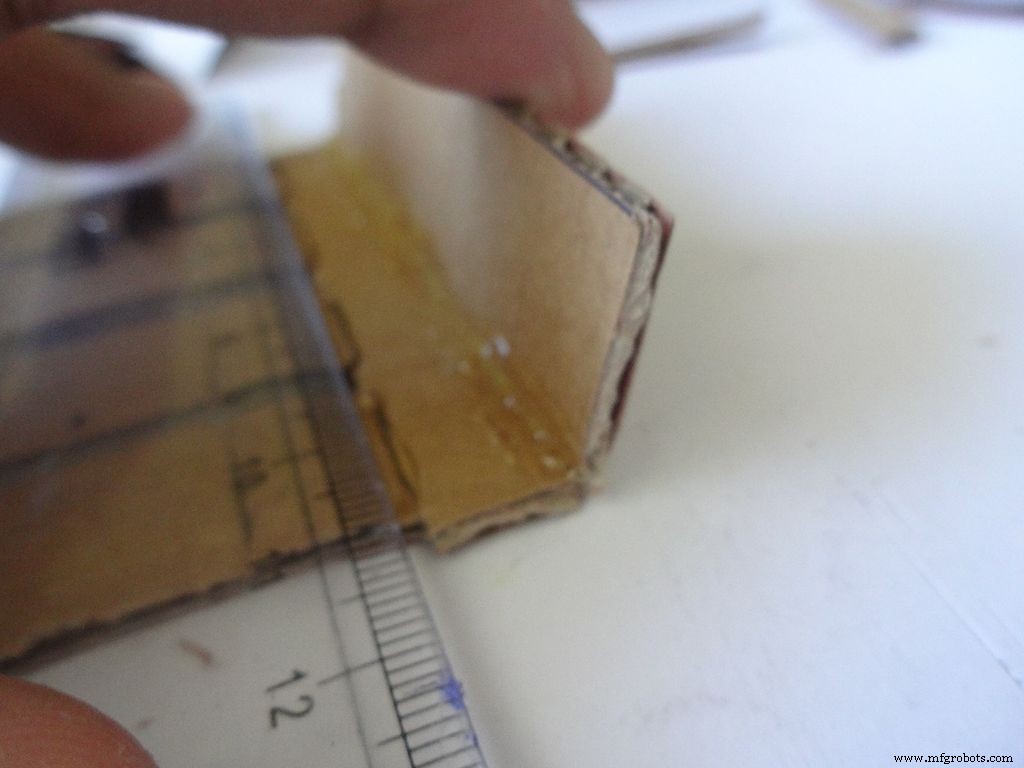
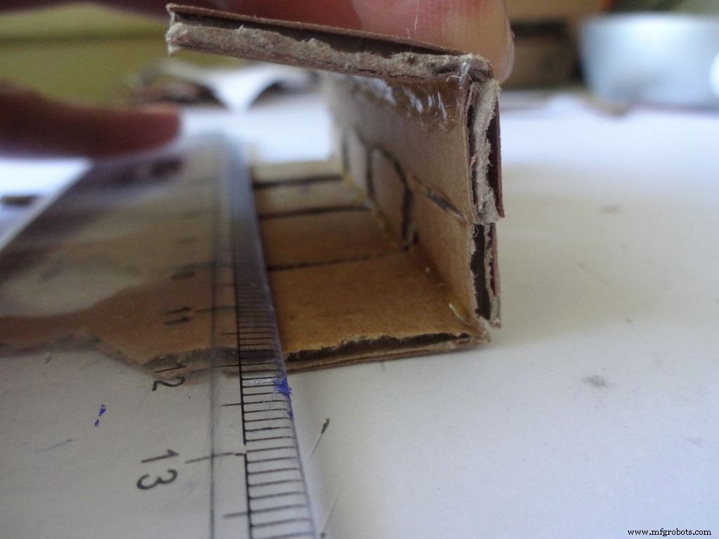
Em seguida, dobre as duas abas laterais para dentro e cole. A parte externa da aba deve ser ligeiramente inclinada e a parte do meio plana.
Etapa 10:Argumentando - Adicionando as opções
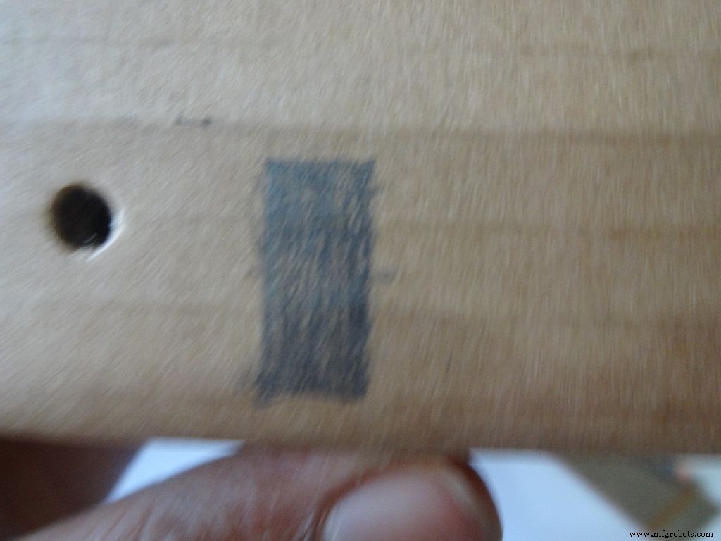
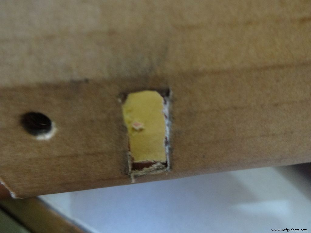
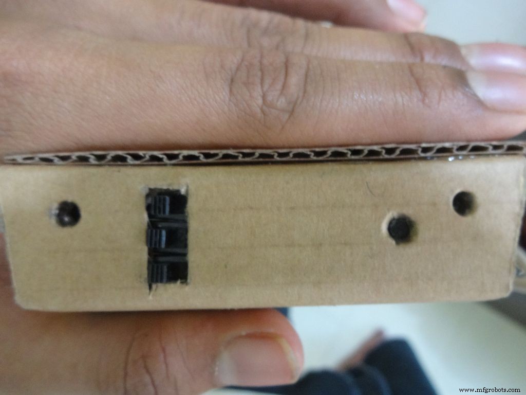

Take the 3 sliding switches with wires we soldered earlier, measure the approximate dimension of rectangle needed. Mark it on the left side of the box(left from the outside). Cut it with a cutter, sand it a bit on the inside to remove any material sticking out.
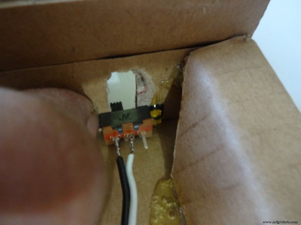
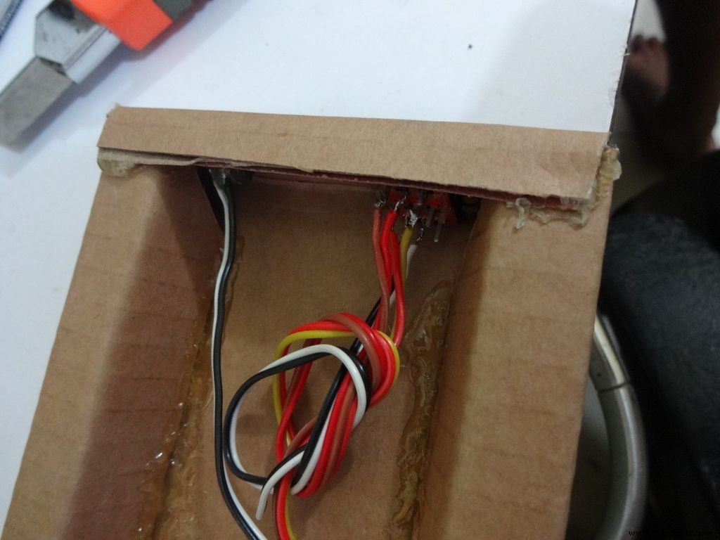
Keep the first switch in position and while holding it add glue on one side. Let it cool. Repeat with the other two as well, and then add glue on the remaining sides. Note:The wired pins of the switches should be on the same side.
Make another hole on the other side for the reset pushbutton. Hold the button in place and add glue. Fold the lower flap inwards and stick it.
Step 11:Making the case - Top half or cover
Sand the edges and stick the side flaps inwards(just like the base) for the top half
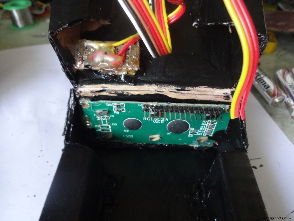
Step 12:Making the case - Adding the LCD
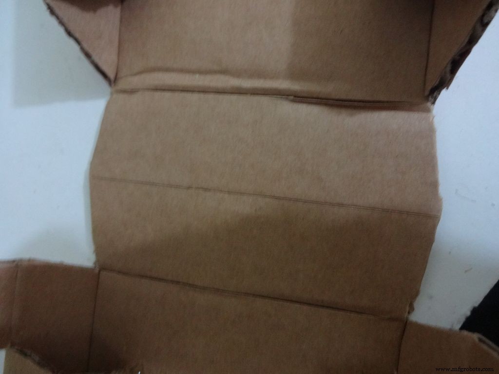
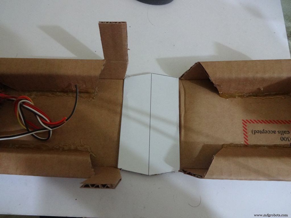
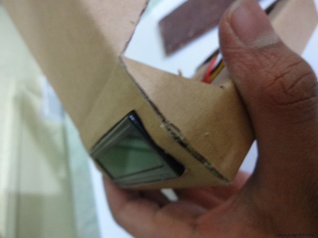
Crease the middle line. (Didn't do it earlier as it is delicate and gets loose soon).
Fold the cover over to the base and check whether everything looks alright, sufficient spacing should be left for the IC pins. (See photo)
Cut the covering flaps as shown in the images.
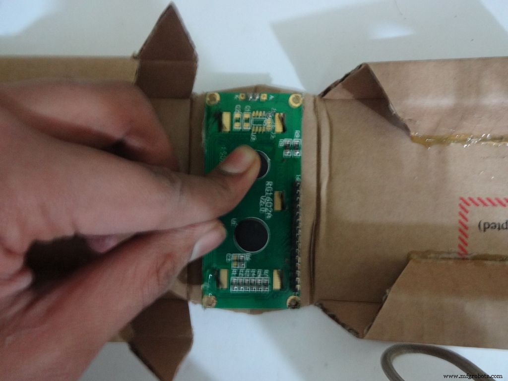
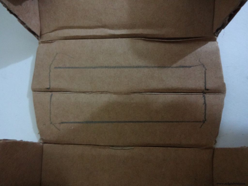
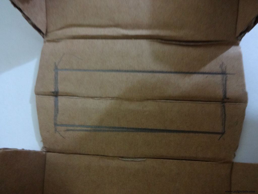
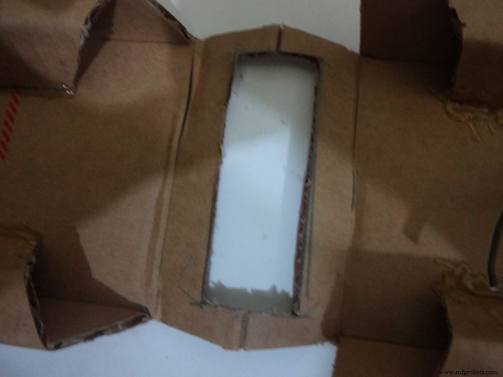
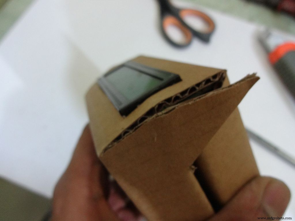
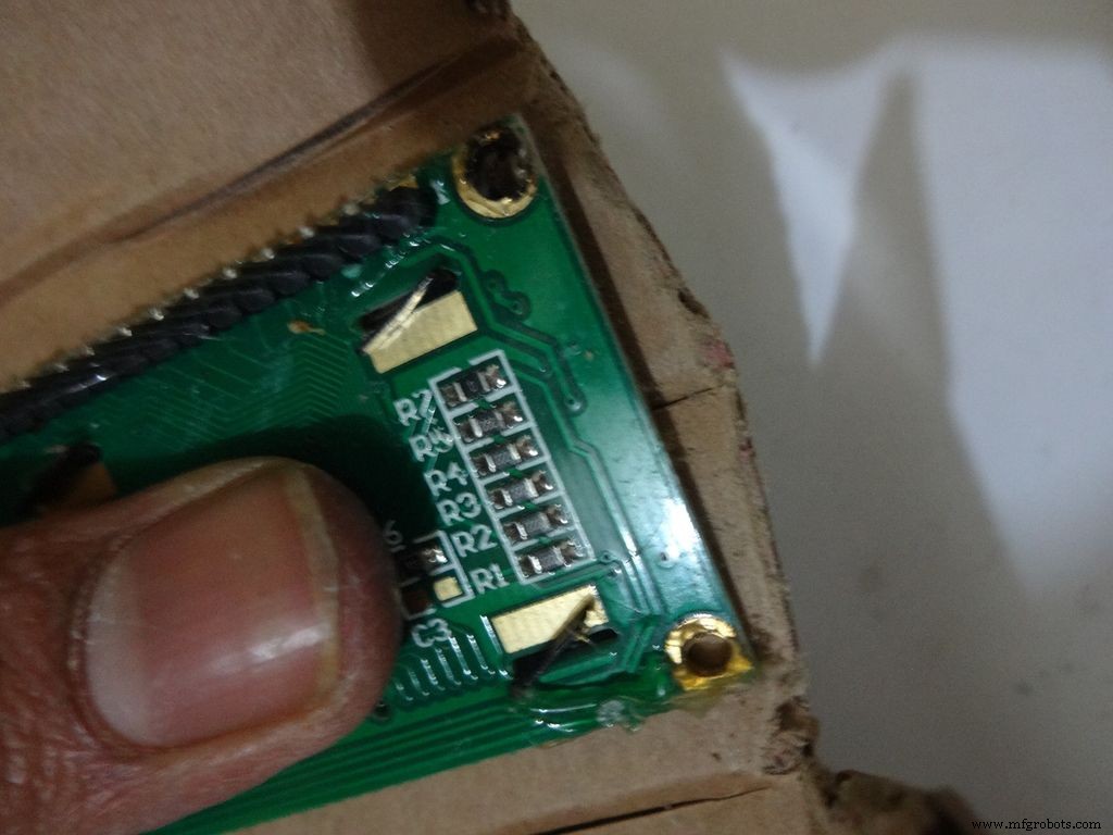
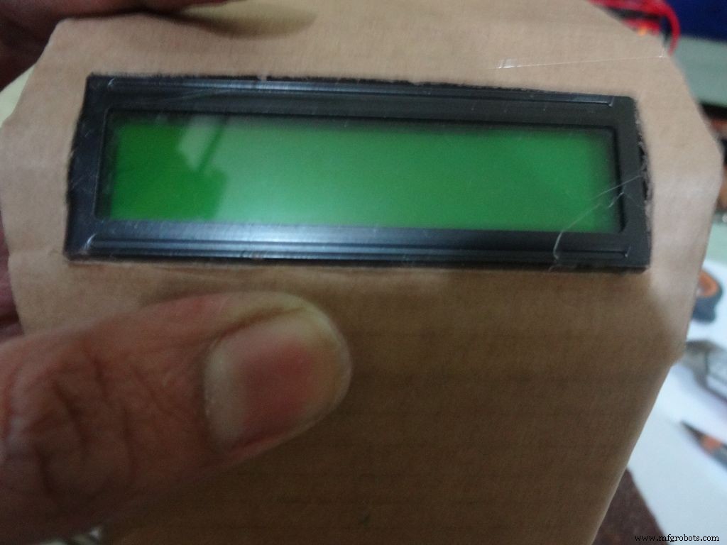
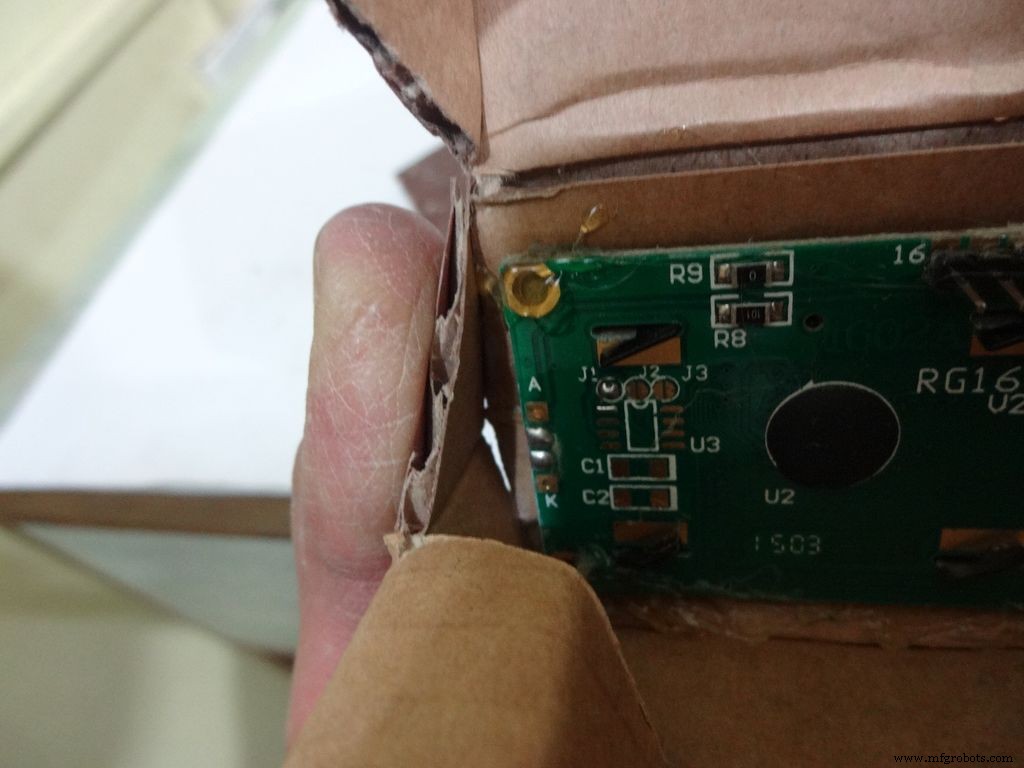
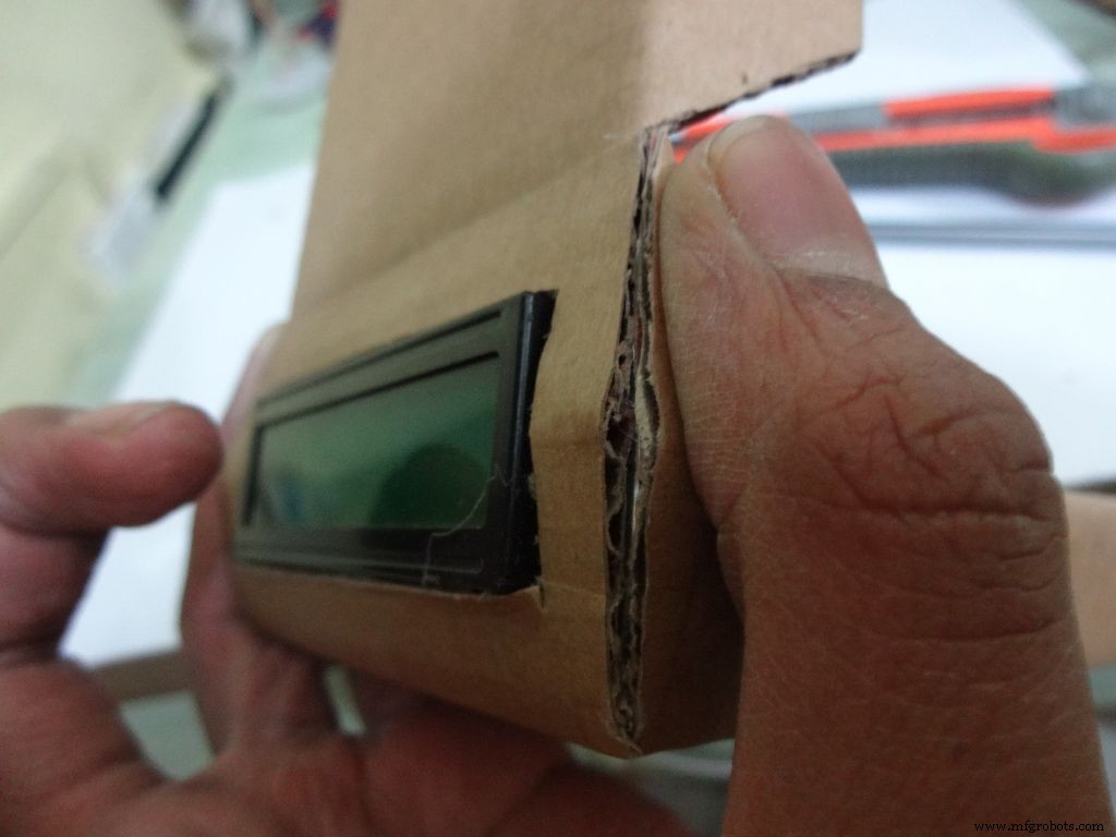
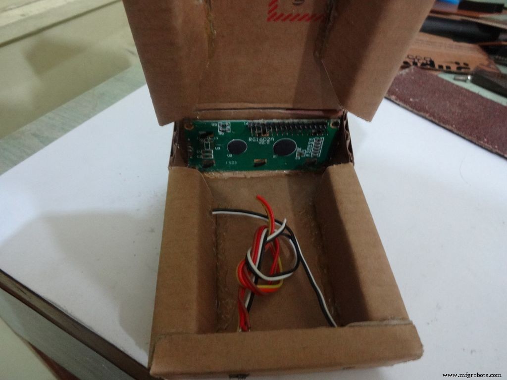
Keep the LCD at the center of the LCD Area, mark it with a pencil. Using a ruler, make the rectangle properly and cut it carefully using a cutter. Fold the LCD window and apply glue to the hinges to keep them at their correct position. Insert the LCD and make any modifications if required.
Finally, apply glue to the four corners(don't put excess) of the LCD and place it in position.
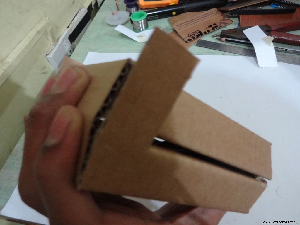
Step 13:Making the case - Final flaps
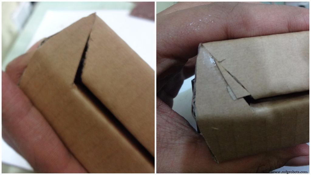
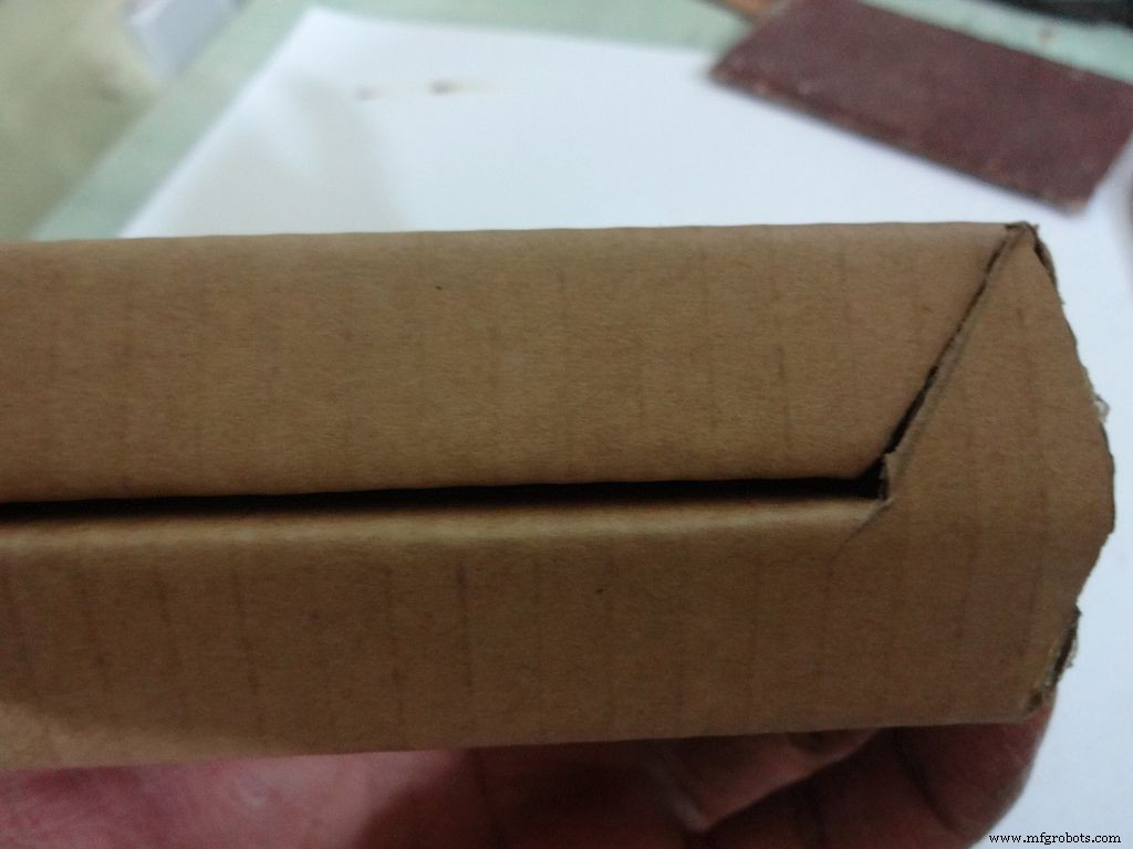
Sand, trim and close the tringular flap.
Make a small piece as shown and stick it to the cover. Make two holes, widen them with a pencil for inserting the bolt and locking the cover to the base.
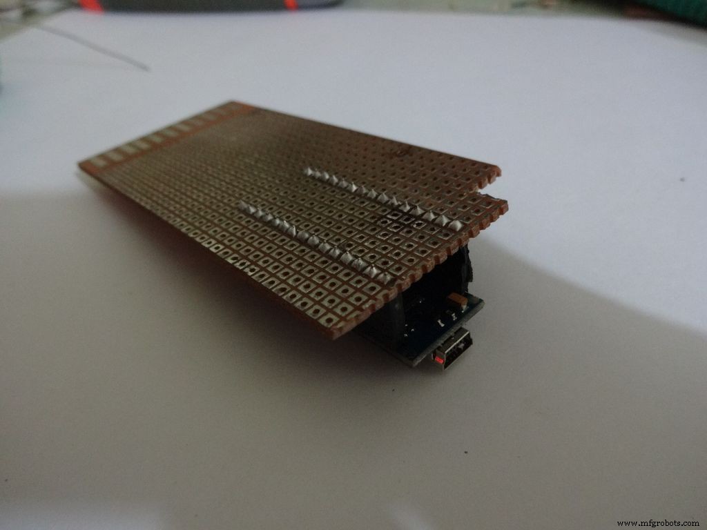
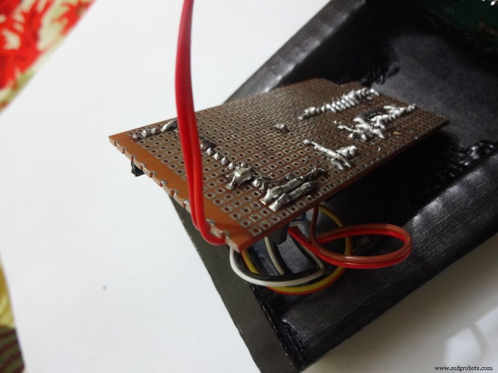
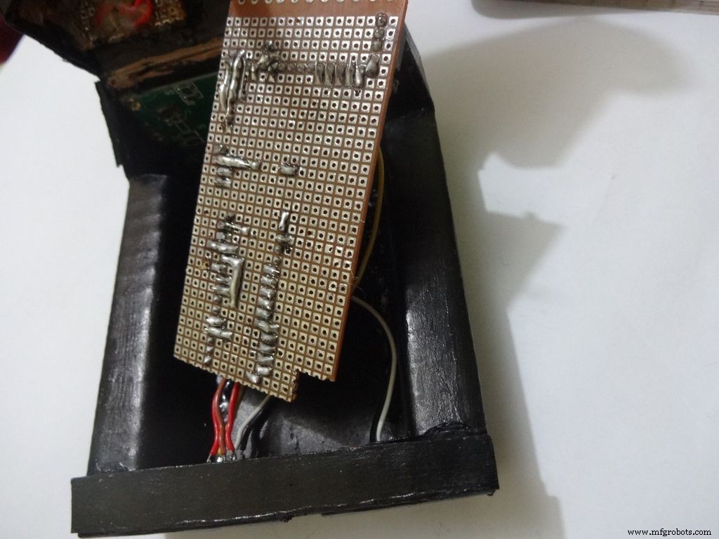
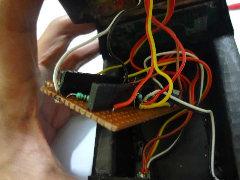
Step 14:The Circuit Board -- Making it fit

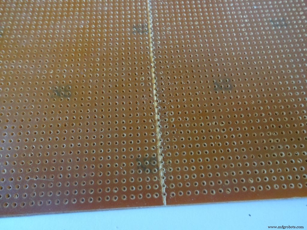
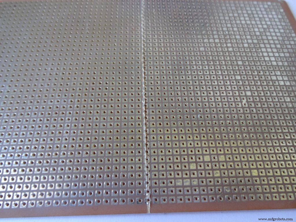
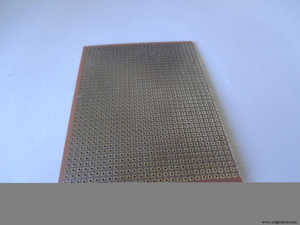
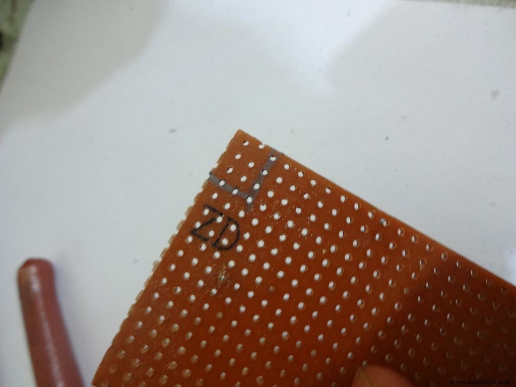
Cut the General purpose PCB to the right size such that it fits properly in the case. Mine is 2x4inches. To cut it, use the ruler and cutter and swipe it multiple times on both sides and it breaks off easily then.
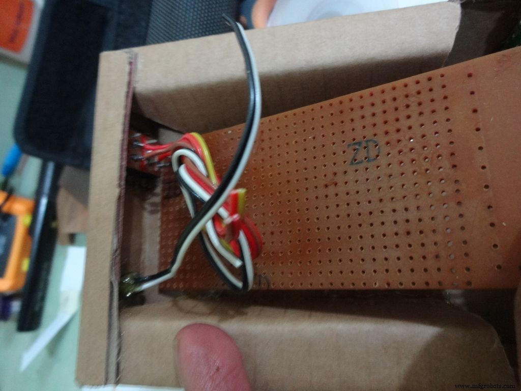
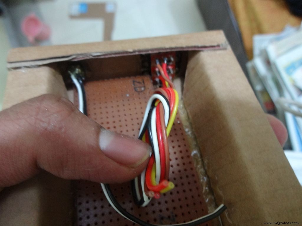
Place it inside. If the glue from the side flap lifts the PCB up, reheat the glue to flatten it or lessen the size of PCB a bit.
Cut a small part so that the 3 switches fit in and PCB goes entirely inside.
Step 15:The Circuit Board -- Arduino Nano

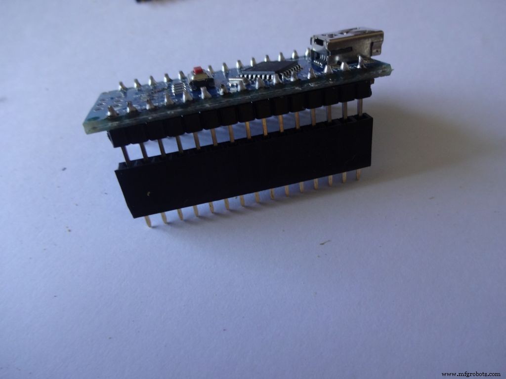
Cut female header pins of the right size for the Arduino.
Place it at the center edge of the PCB and solder all the pins.
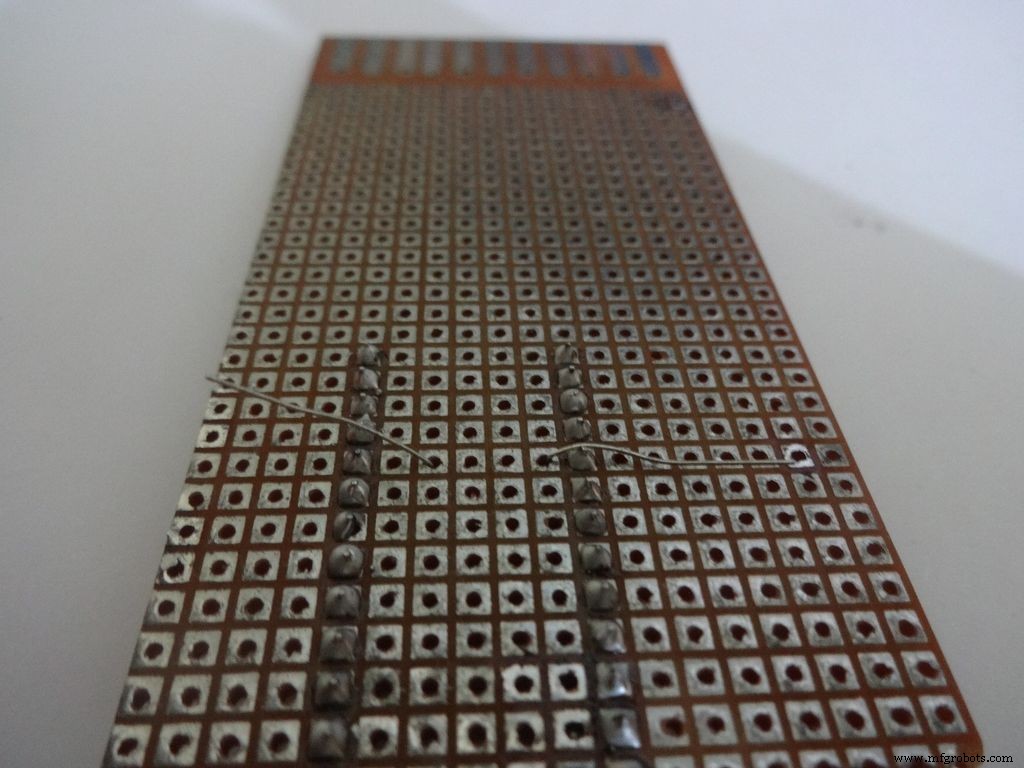
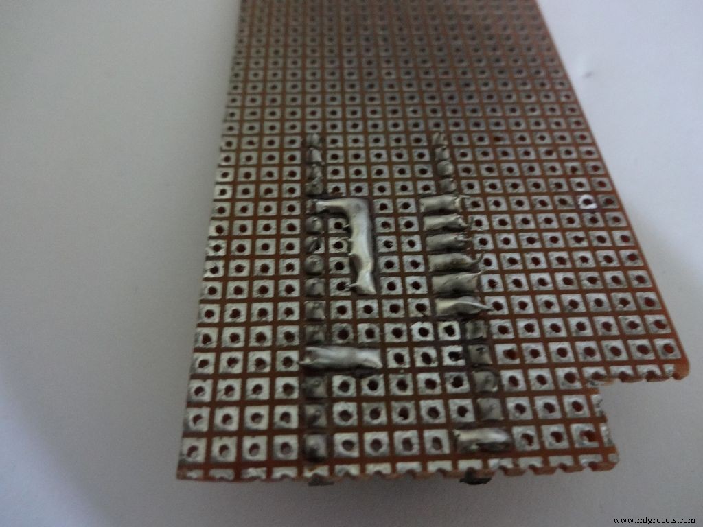
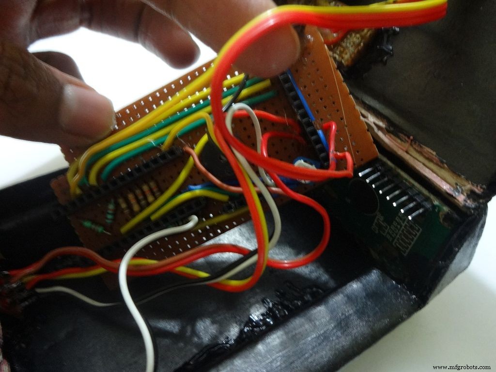
Step 16:The Circuit Board -- Ohmmeter
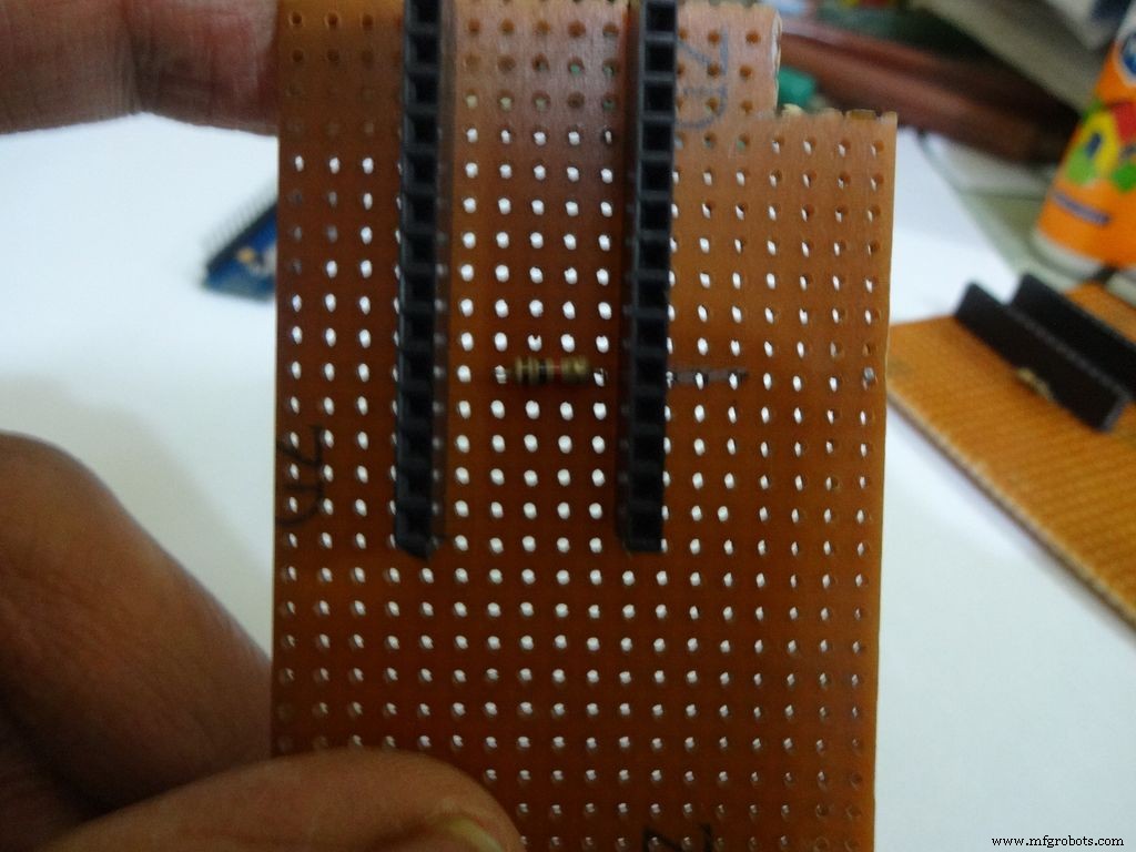
Before making any connections on the PCB please double check from the final Circuit Design.
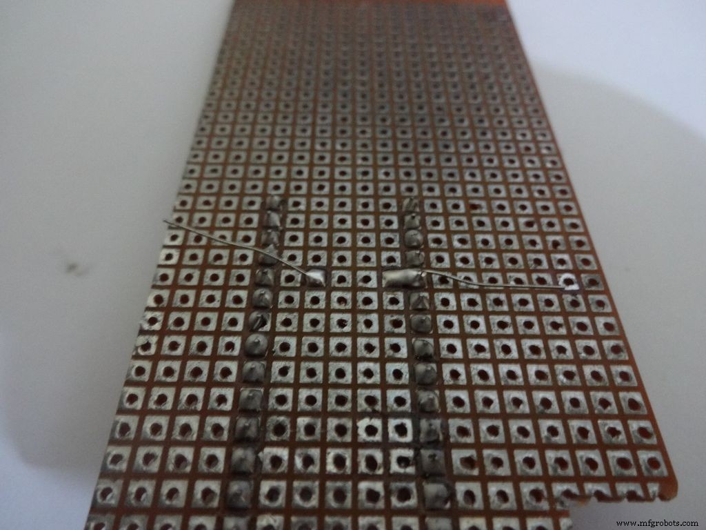
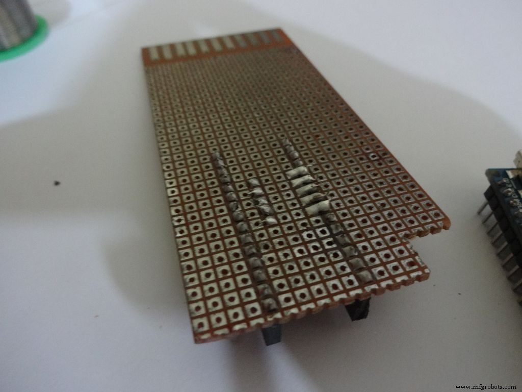
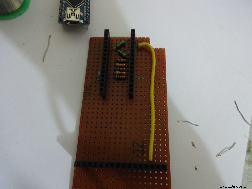
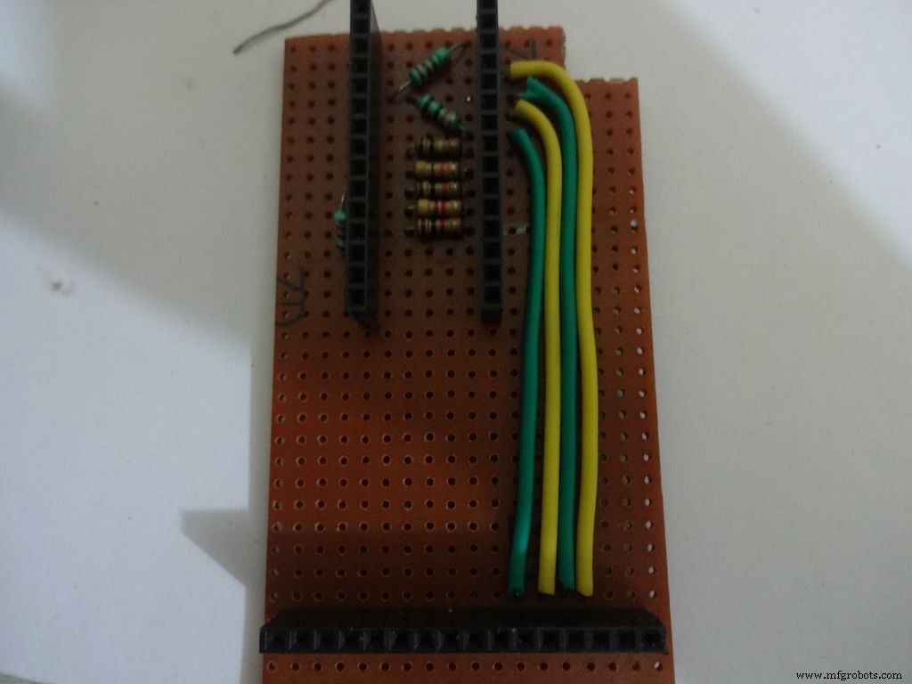
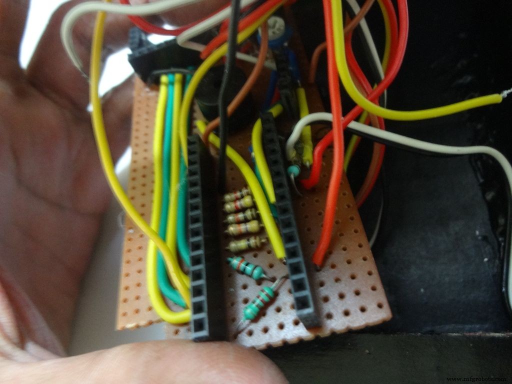
For the ohmmeter start by adding a 1k Ohm resistor to pin D2 of arduino. Place the arduino and carefully mark the pin. On the reverse side, bend as shown and solder it.
Do the same with the other 4 resistors, 4.7k, 10k, 47k and 100k Ohm.
Note:keeping all the tolerance bands(gold band) on one side is a good practice, eg UP and RIGHT.
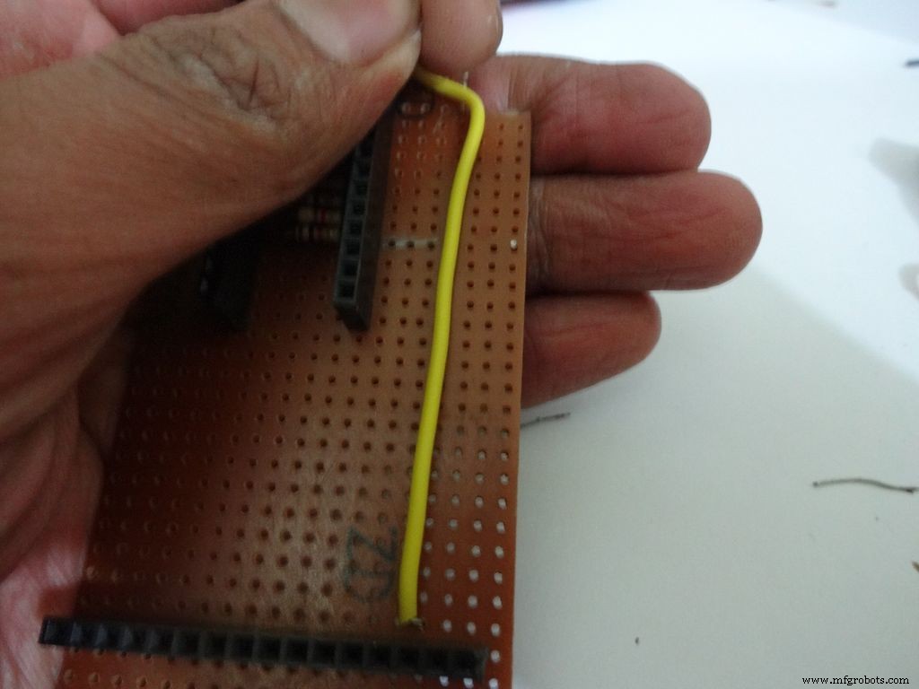
Combine the second ends of resistors and solder it to A7 .
Step 17:The Circuit Board -- Capacitance Meter and Diode Test
Capacitance Meter:
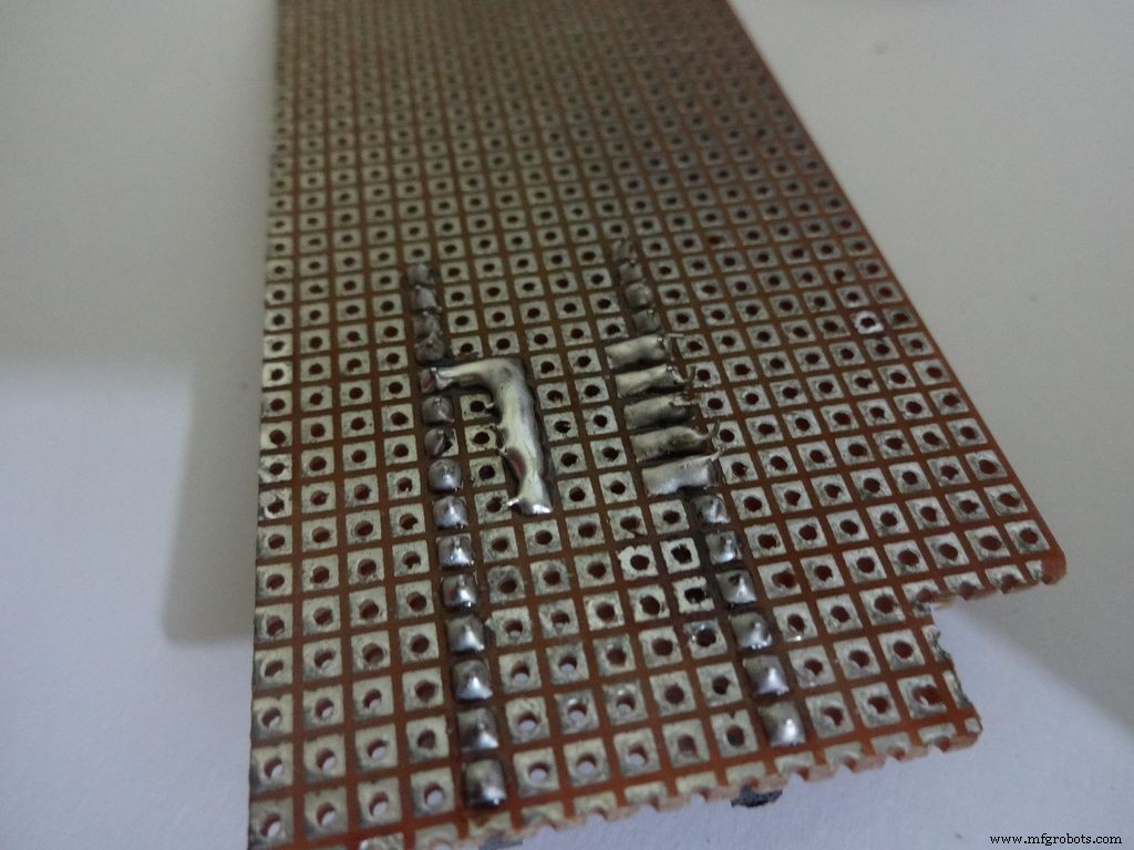
Solder a 220 Ohm resistor from D12 to A0 . And a 10k Ohm resistor from A0 to D7 .
Note: D7 (digital pin) is also used for LCD data pin D4 .
Diode Test:
Solder the 10k Ohm pullup resistor from A6 to +5V .
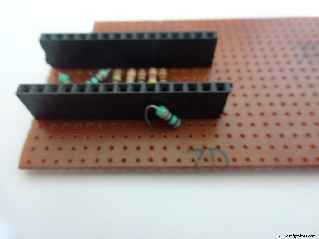
Step 18:Making connectors for LCD
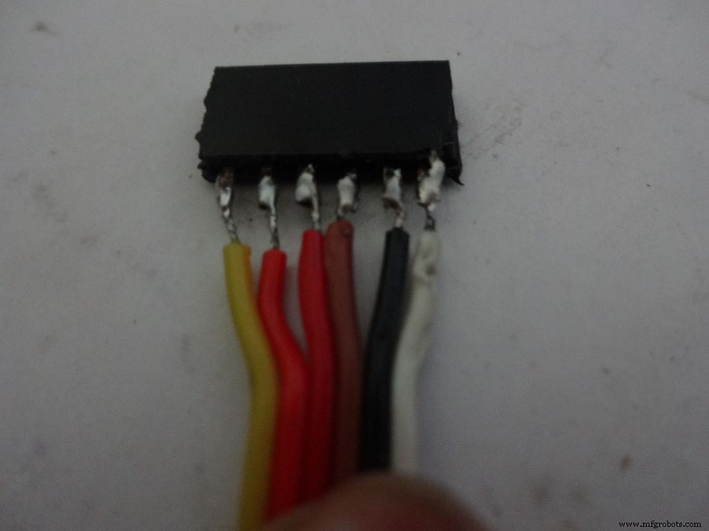
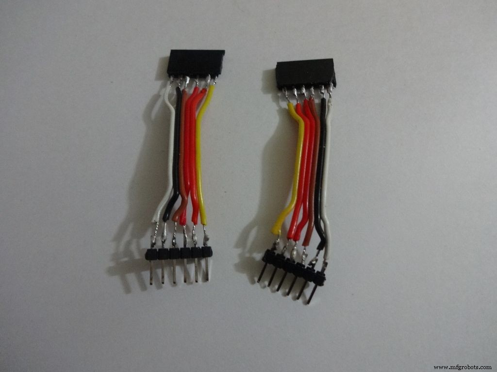
We just use the first 6 and last 6 pins on the LCD. Pins D0-D3 are unused. So we will be making connectors for only the used pins. It is recommended that you do the same because plugging/unplugging a 16pin connector becomes very tough once the build is complete.
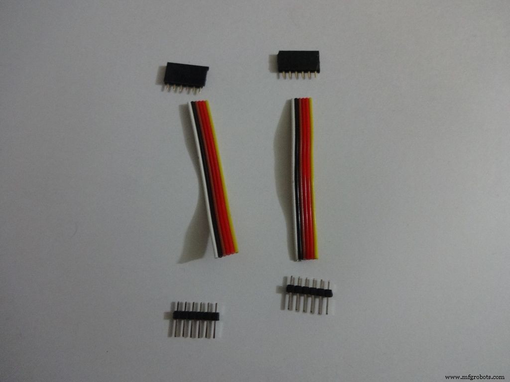
Cut 2x 6pin female and male header pins. Also take 6 wire ribbon cable, around 2-2.5 inches long.
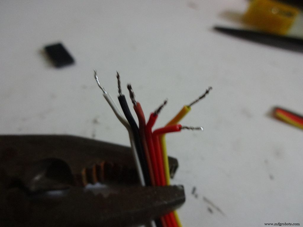
Strip the insulation and tin the leads. Also tin the header pins. Join them one by one just like the slide switches.
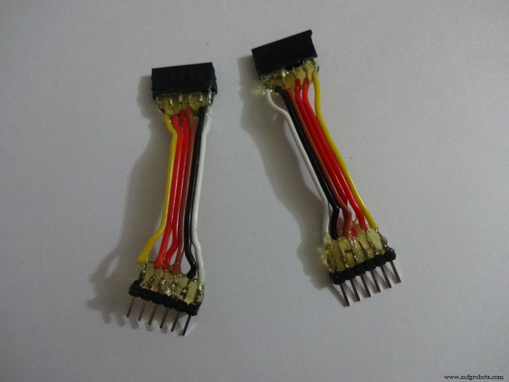
Apply hot glue to secure the wires.
Step 19:The Circuit Board -- LCD connections
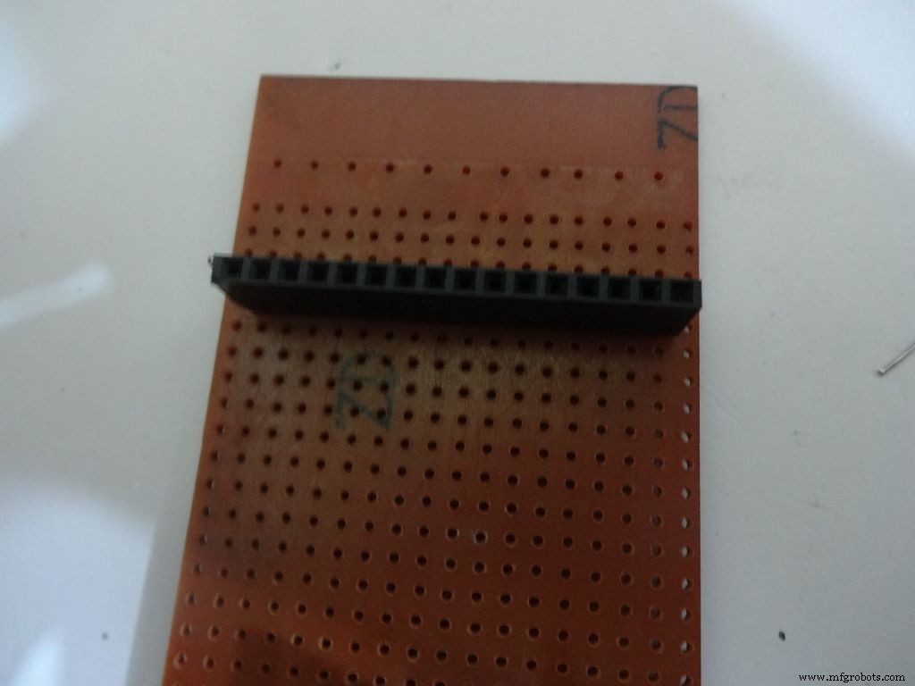
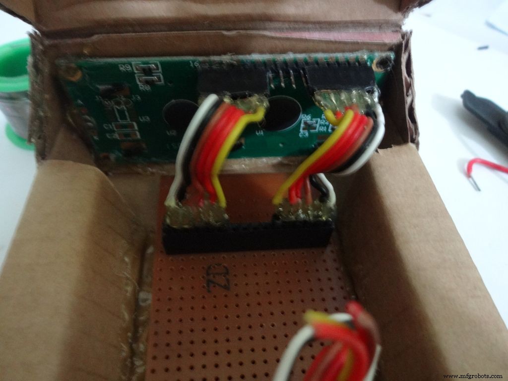

Place the PCB inside the case. Plug the connector to LCD and see where the female port should be on the PCB, solder it.
Make sure you leave 4-5 dot rows behind the LCD port. The Power switch will be added here later.
Measure the length of single stranded wire needed to connect data pins (D4 , D5 , D6 and D7 ) on the LCD to digital pins( D7 , D8 , D9 and D10 ) on the Arduino, respectively.
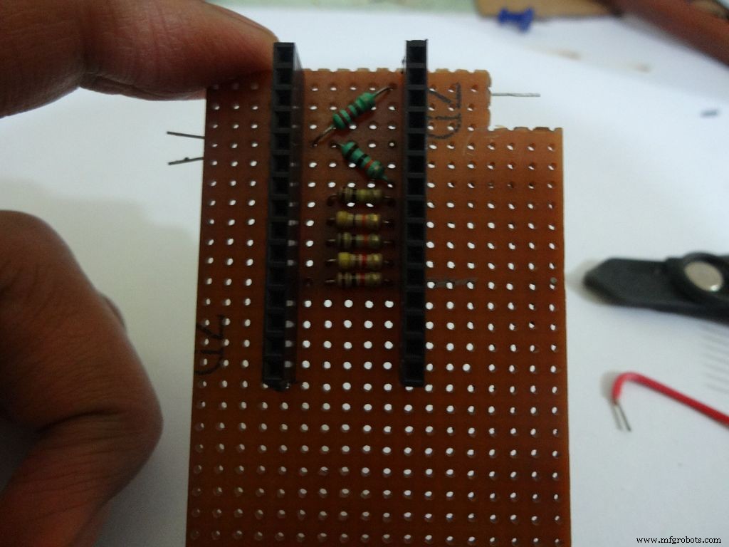
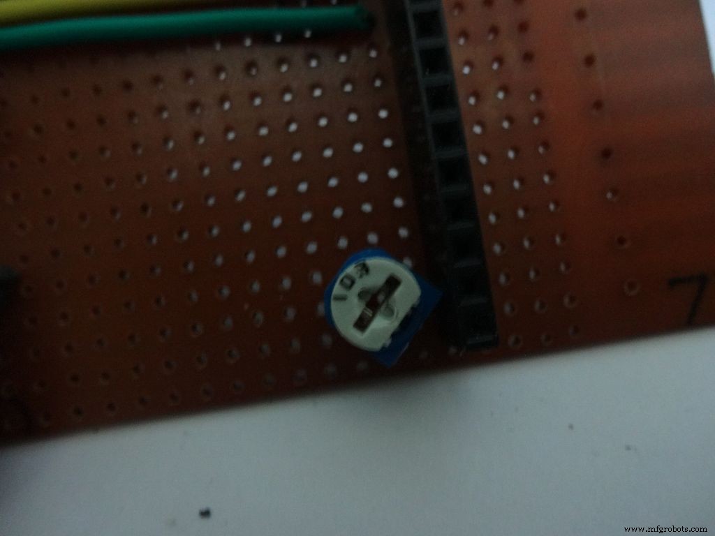
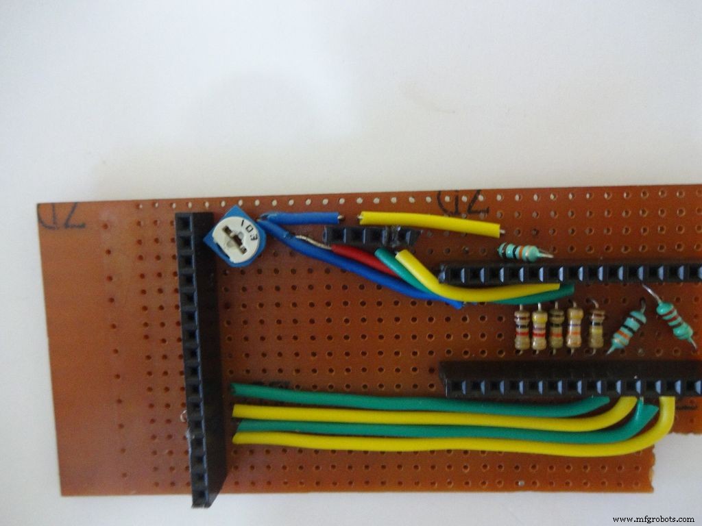
Add the 10k ohm potentiometer such that the side ends go to Vcc , GND and the middle pin to V0 .
Connect Vss(GND) on the LCD to GND , and Vdd to +5V . Also connect R/W to GND .
Arduino Pin
LCD
D7 D4 D8 D5 D9 D6 D10 D7 GND Vss(GND) +5V Vdd
Step 20:The Circuit Board -- RTC Module
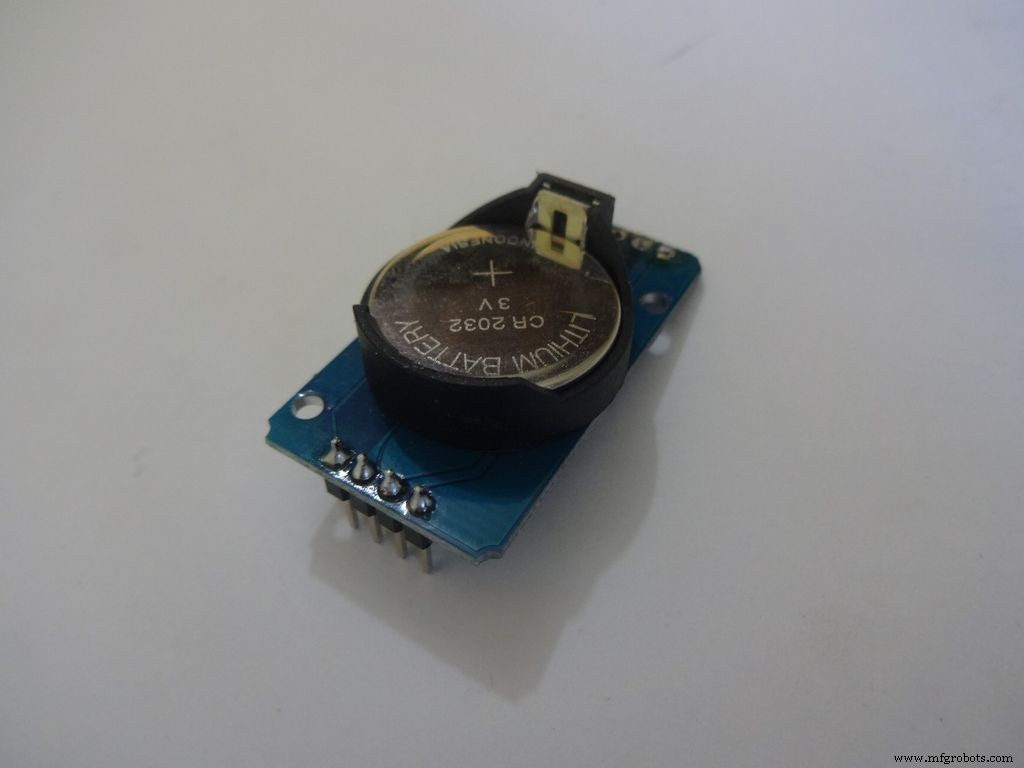
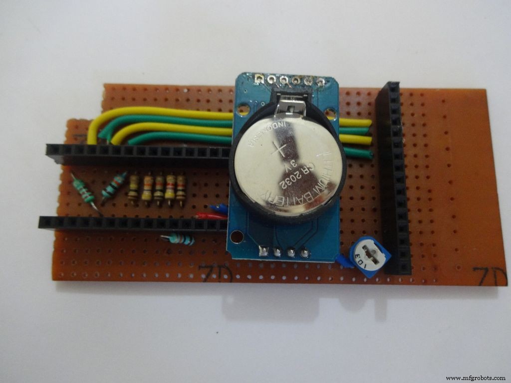
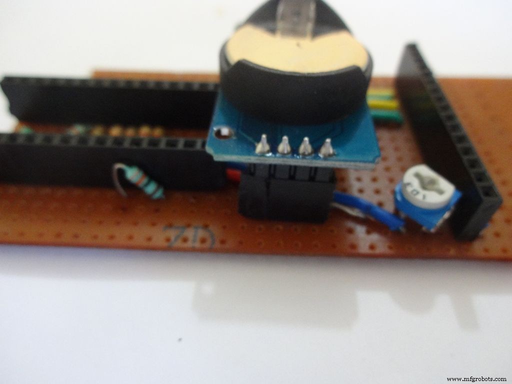
I desoldered the default 90 degree header pins on the module and added straight ones so that it fits flat on the PCB.
Solder 4pin female header pin and make connections to Vcc , GND , SDA to A4 and SCL to A5 .
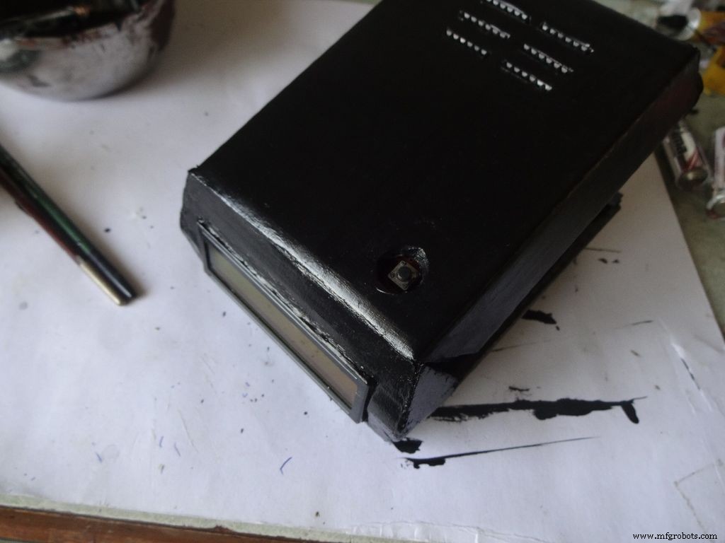
Step 21:Making the Case -- The mode button
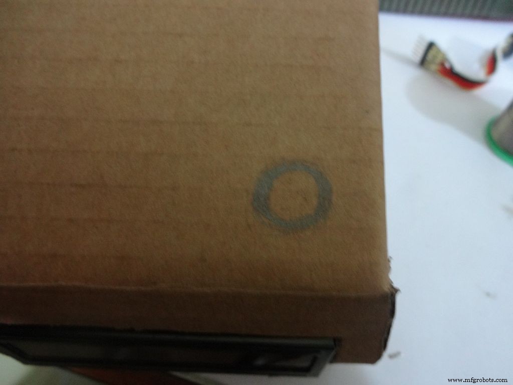
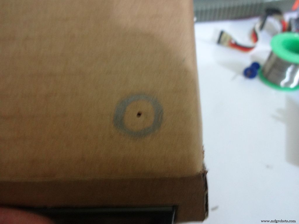
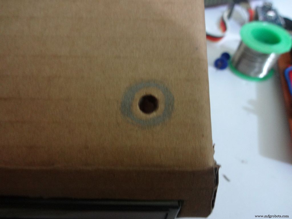
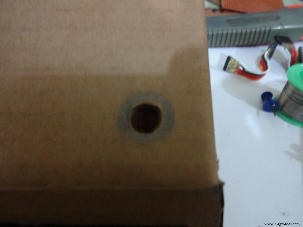
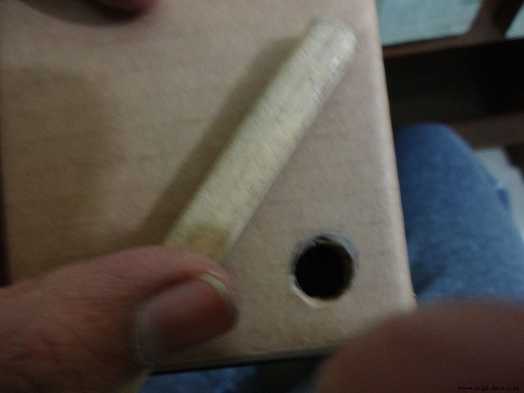
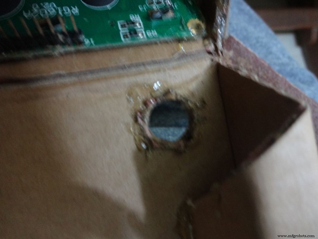


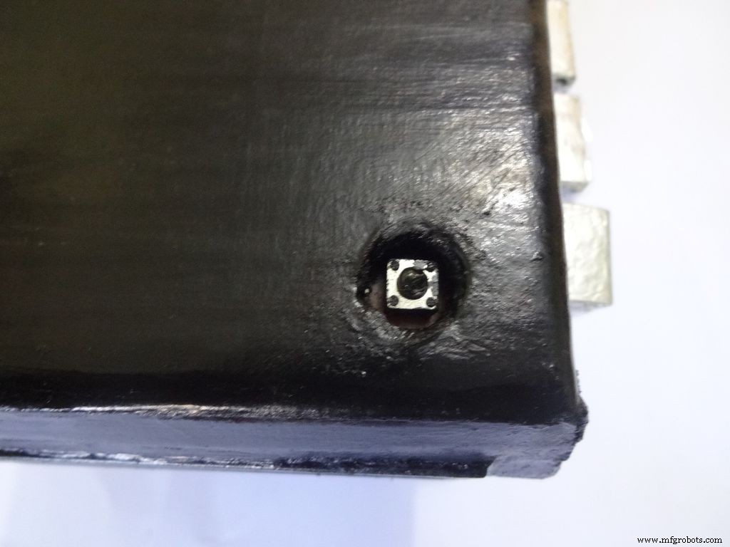
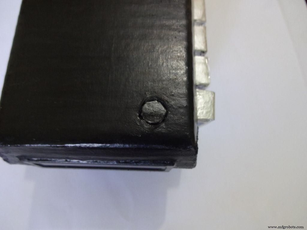
Mark a circle of about 1cm diameter at the pin1 corner of the IC case. mark the center with a pin, use a pencil to expand it. After that use some appropriate tool to increase the diameter to 1cm. Sand it on the inside and use hot glue to secure the hole.
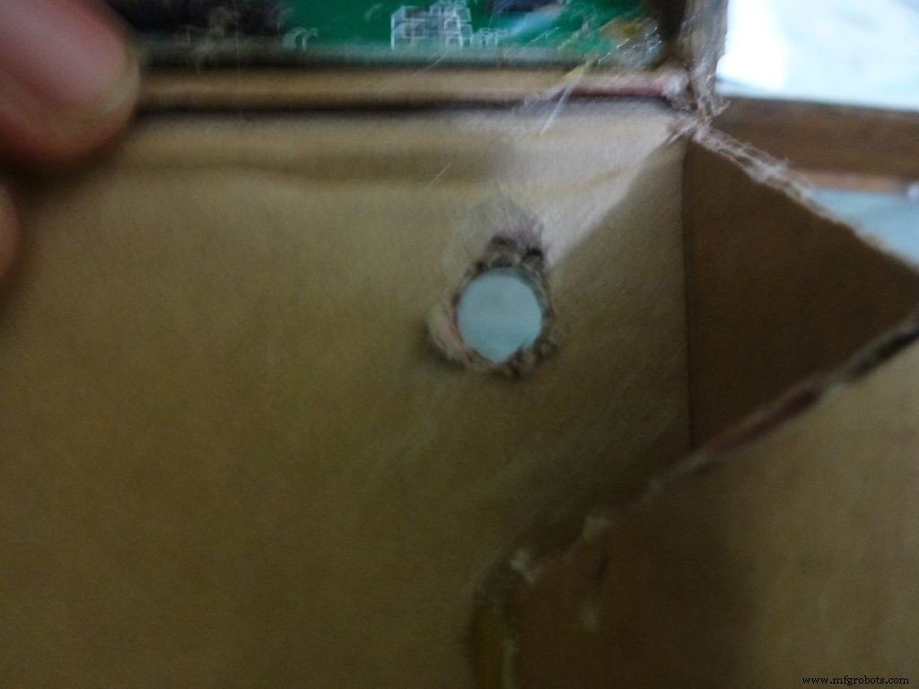
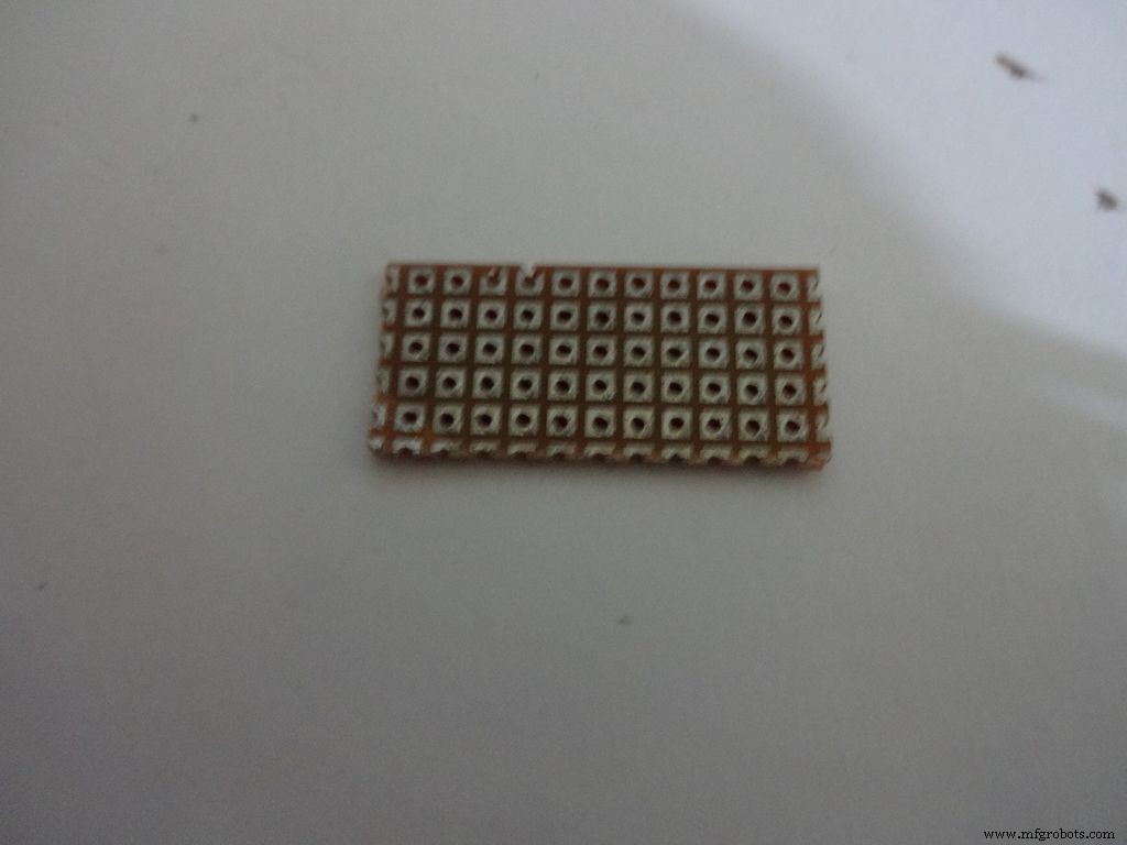
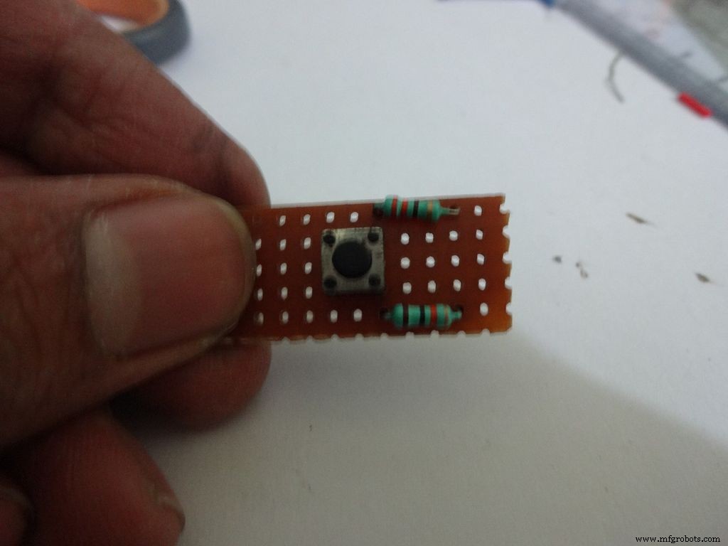
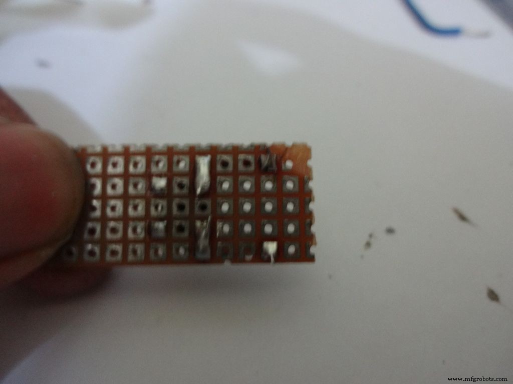
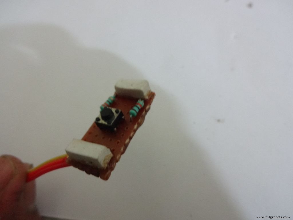
Cut a piece of General purpose PCB (10-11)dots x 5dots. Plug in and solder the pushbutton, 220 and 10k Ohm resistors as shown.
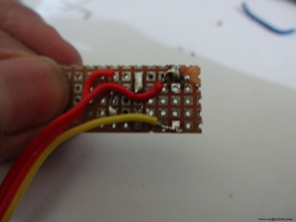
Take 3wire ribbon cable about 15cm long. Tin the ends and solder it as shown. Note down which colour wire goes to where, this will be helpful later on.
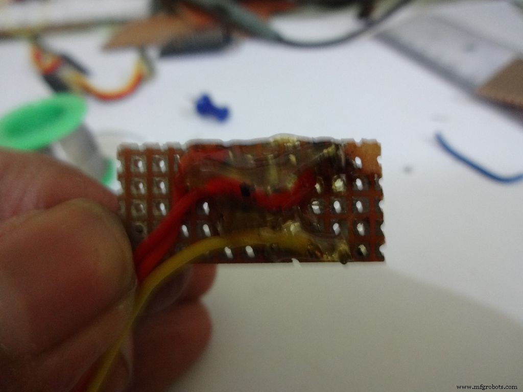
Cut 2 small pieces of eraser and place it on the ends on the board. The height of the eraser should be such that the button is below the cardboard inner level as viewed from outside. I used 4mm.
Secure it with hot glue as shown
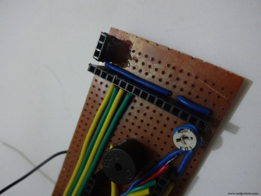
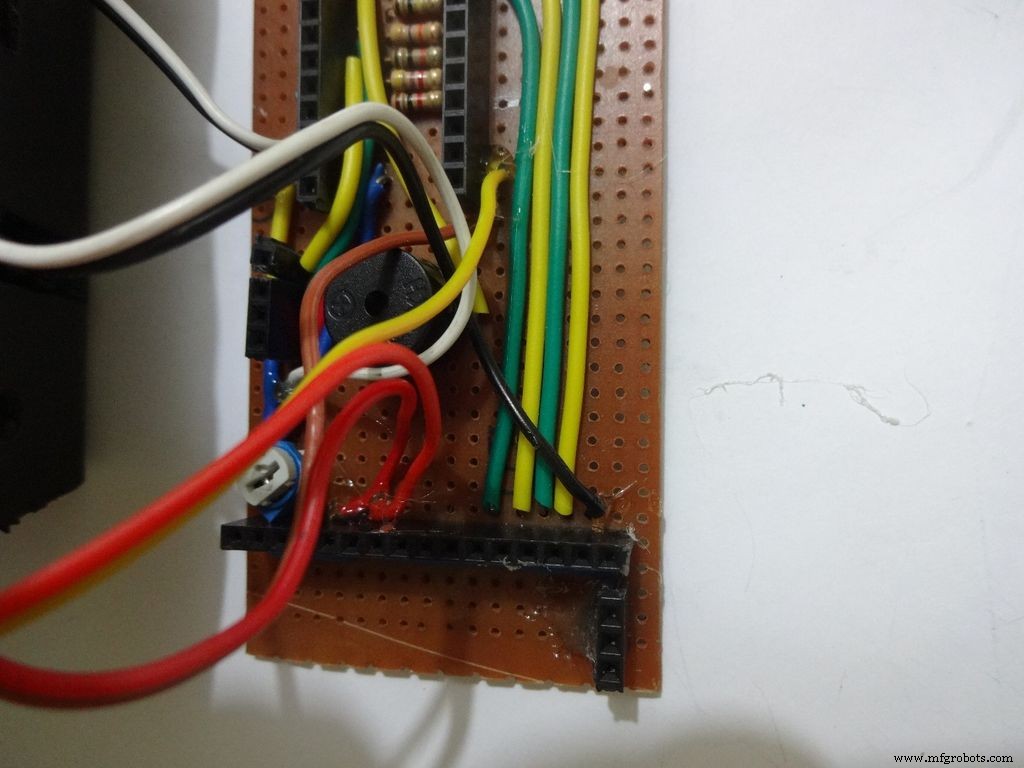
Step 22:Making the Case -- Testing points
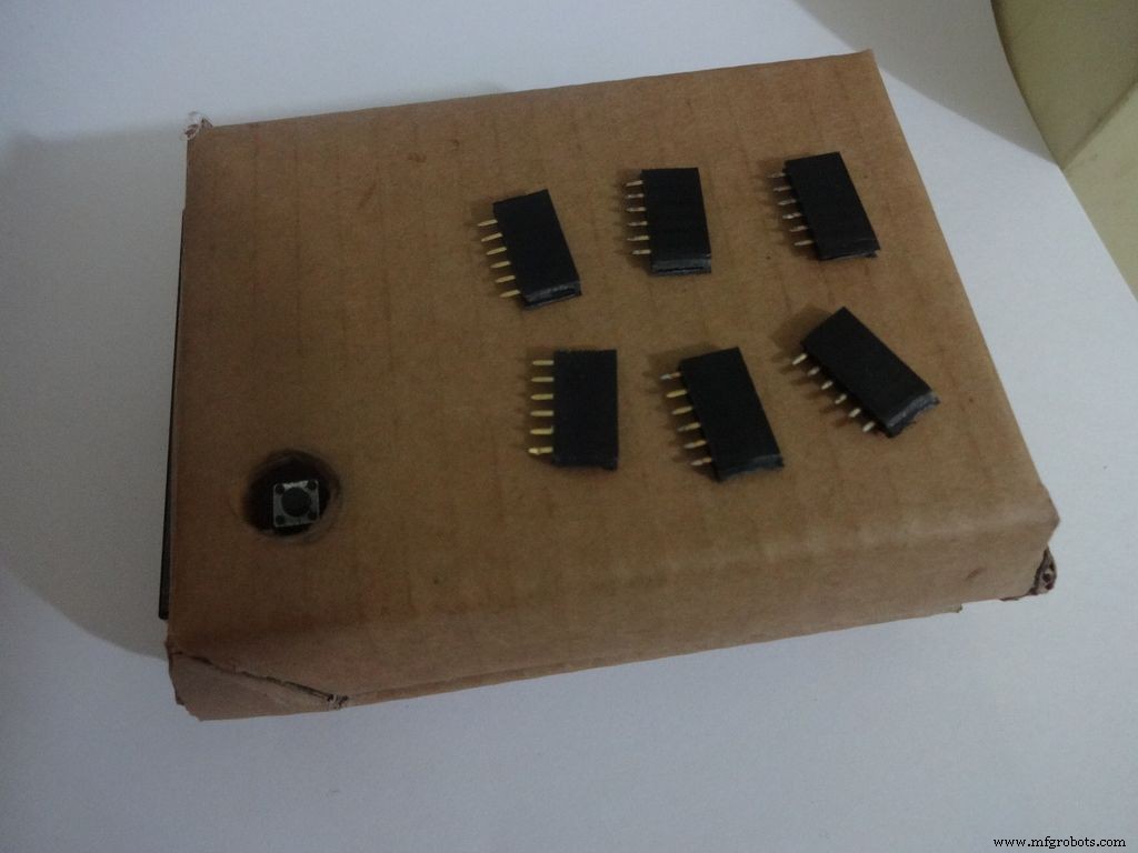
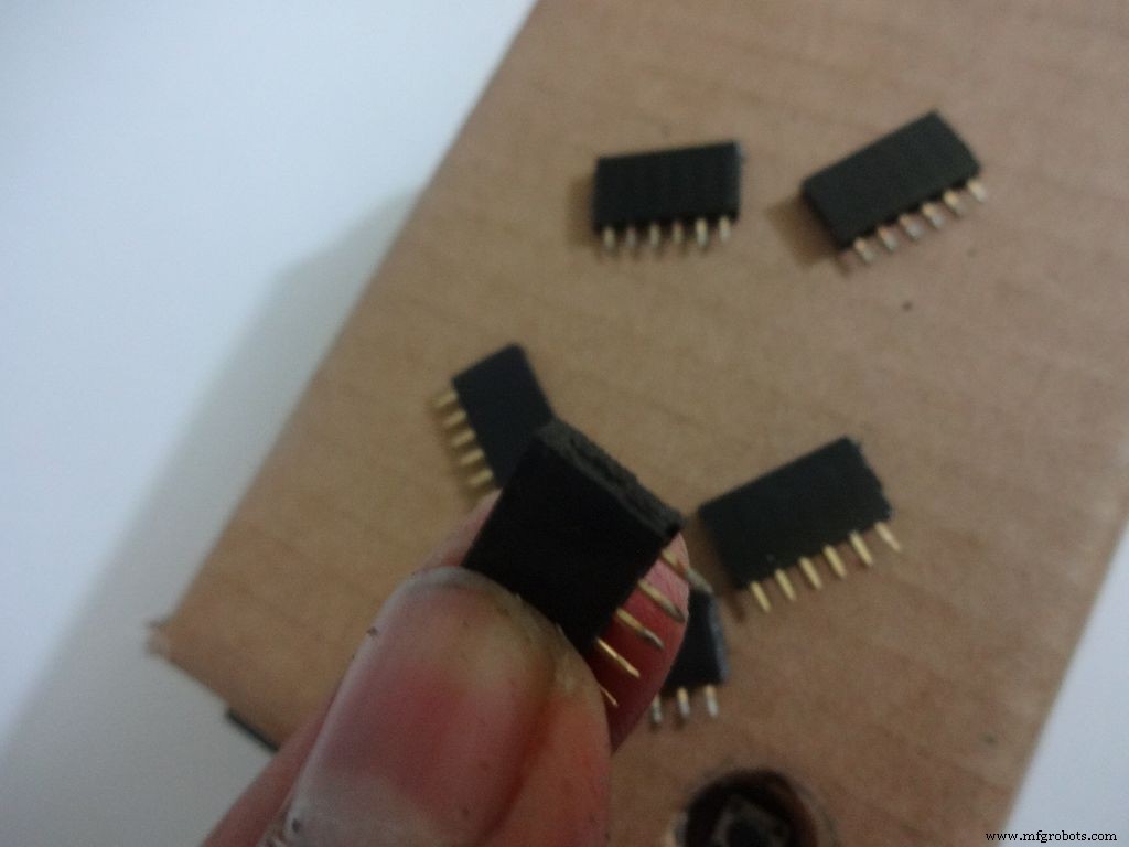
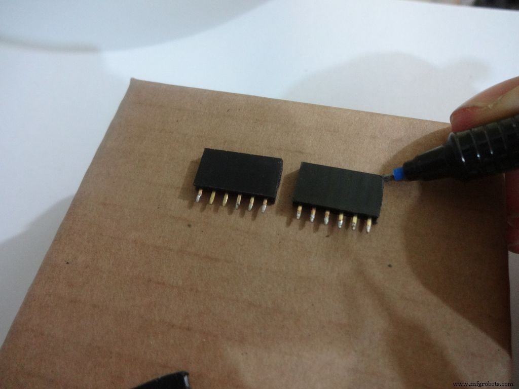
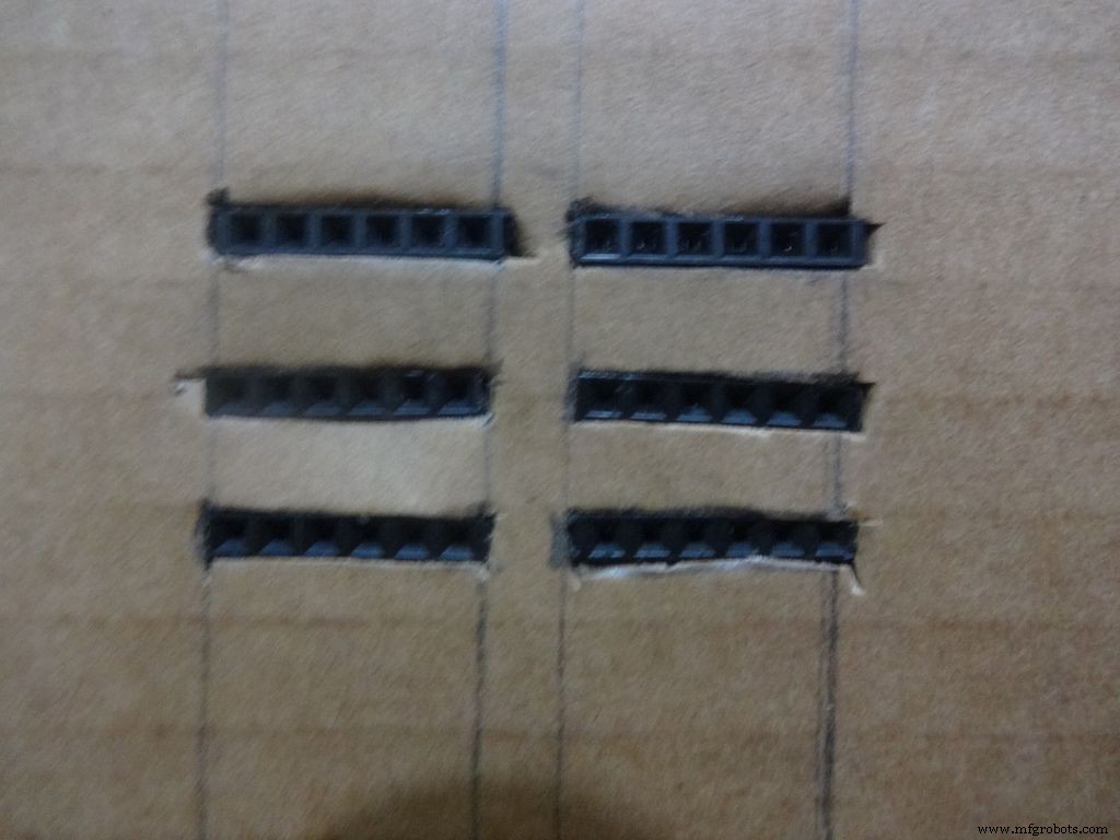
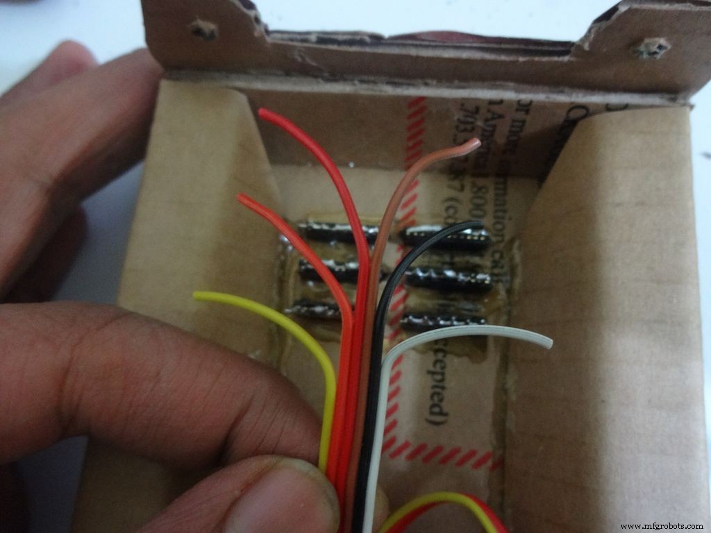
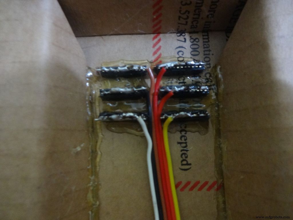
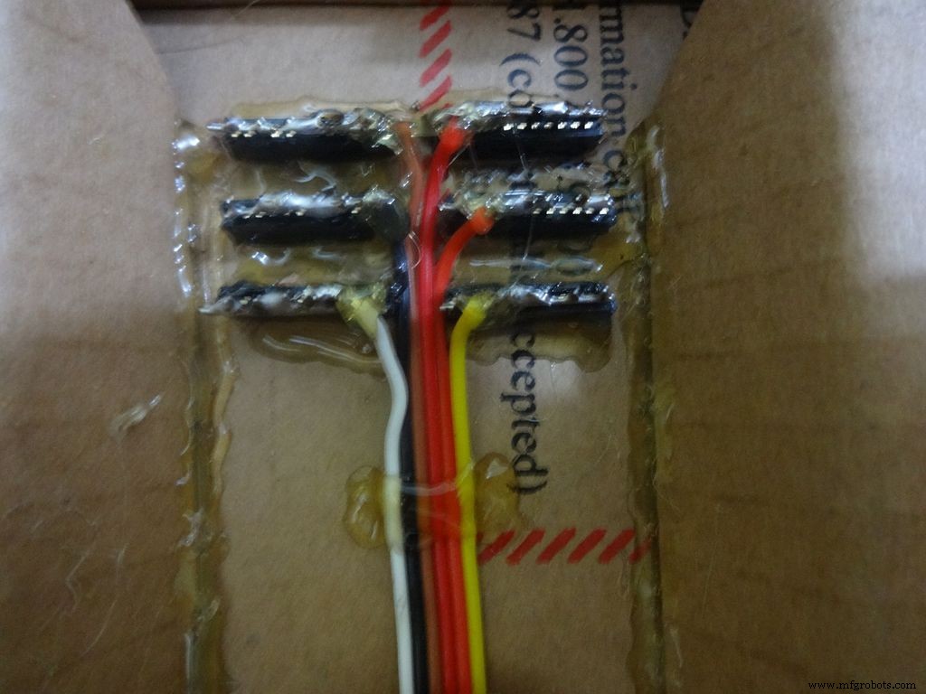
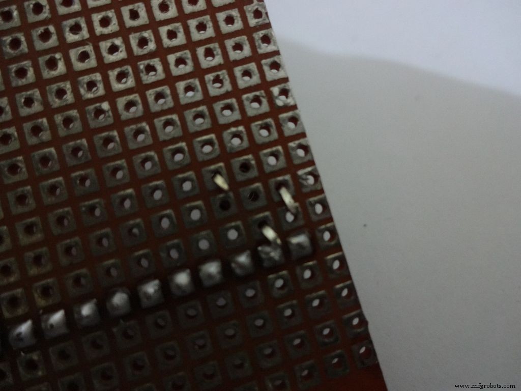
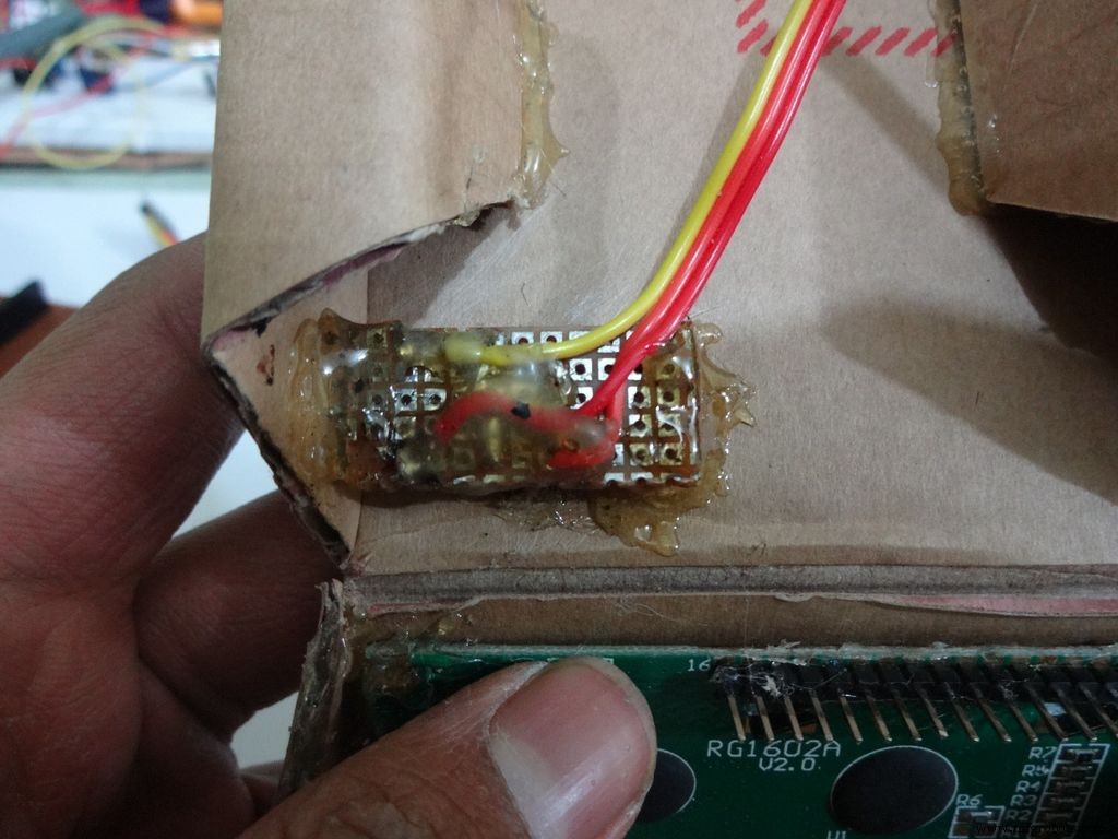
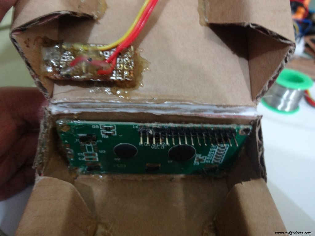
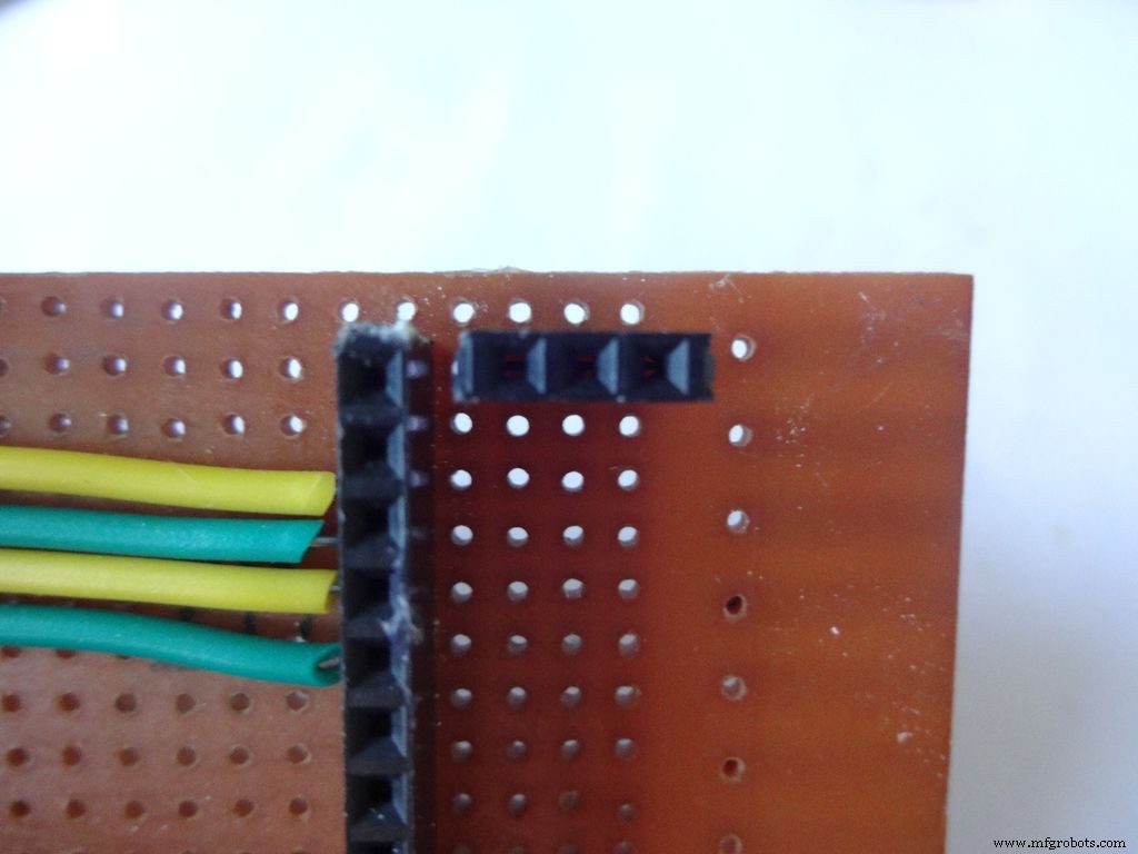
Cut 6x 6pin female header pins. Sand the sides to make it smooth.
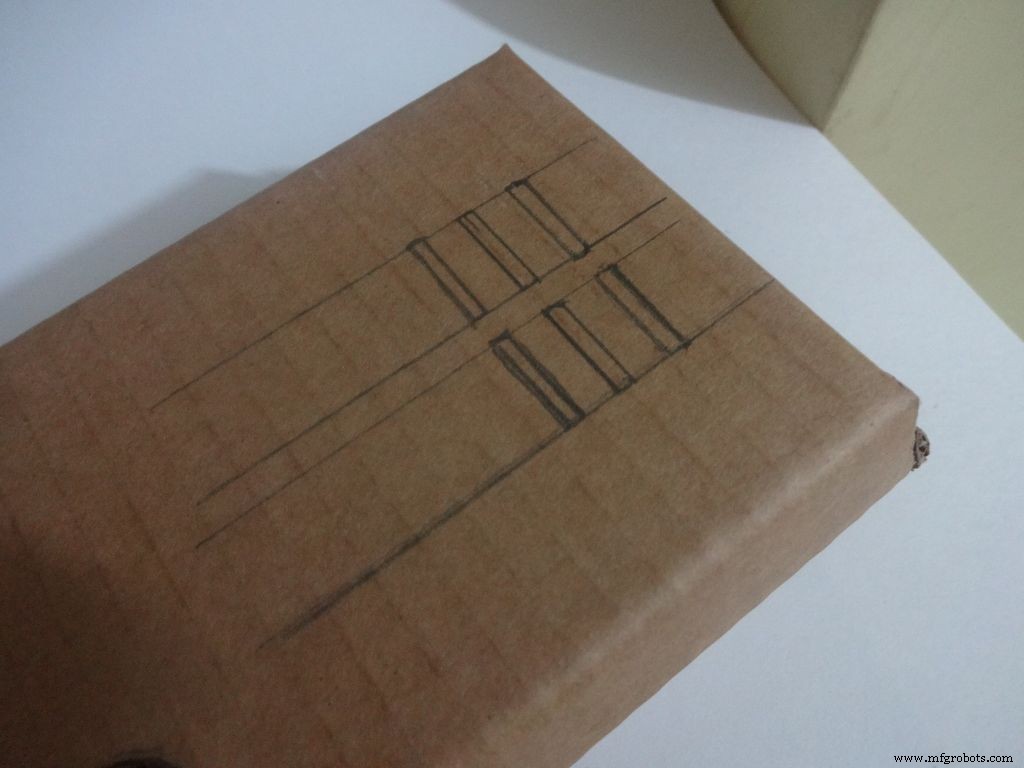
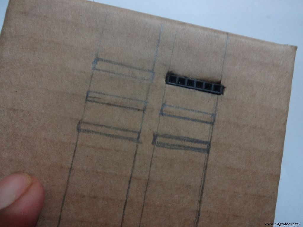
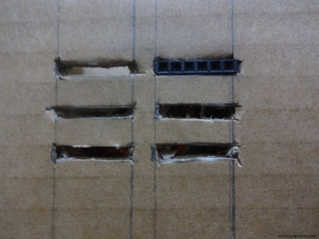
Mark the positions and cut slots for the header pins. Insert it in place and glue it from the inside.
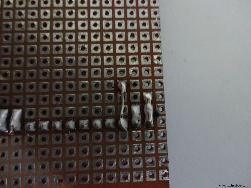
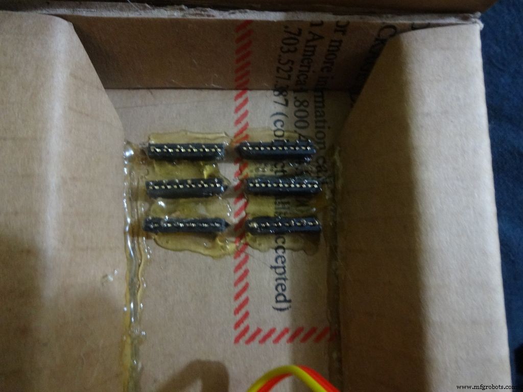
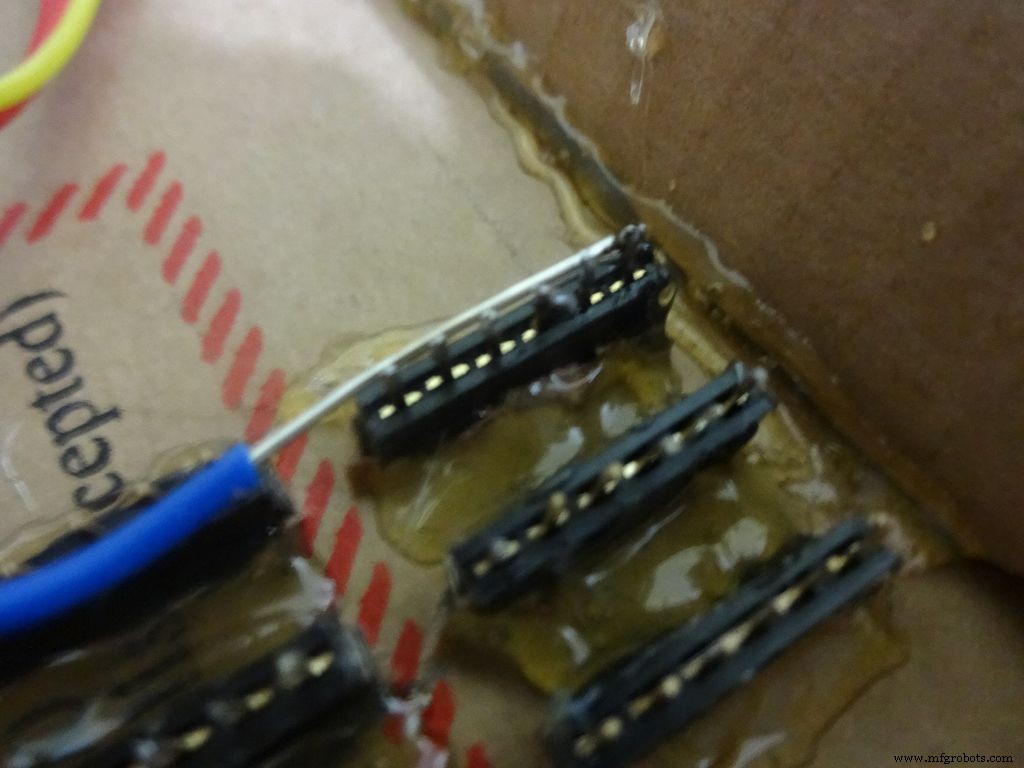
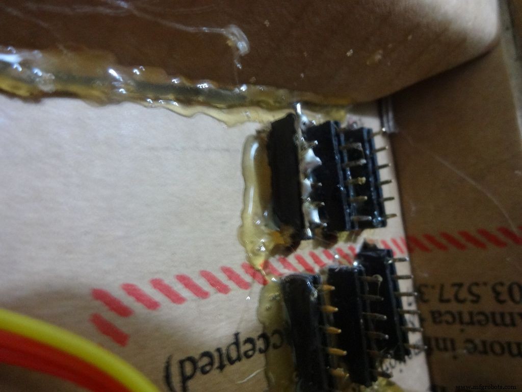
Apply small amounts of solder to all the pins and use a stripped jumper to get it all together. Make sure all of them are connected. Dont keep on heating it to make it perfect. Heating a pin also heats the neighbouring ones.
Take 6 stranded ribbon cable, tin it and attach it to each slot. Note that I put dark colours to the negative side. Apply hot glue to fix them in place.
Step 23:The Legs


Download "Legs_A4.pdf" or ""Legs_ANSI_A.pdf", based of paper size available in your region. attached at the end.
Print it on an A4 size paper (21 x 29.7cm or 8.27 x 11.69 inches) or the US-alternative ANSI A(8.5 x 11inches or 21.6 × 27.9cm). Make sure that while printing you select the proper paper size, orientation, and select the "Actual Size" option. Confirm that the print is accurate by measuring the rectangle. It should be 8.4 x 11.8cm
Cut crease and glue it just like the main case, see the images.
Step 24:Making it shiny!
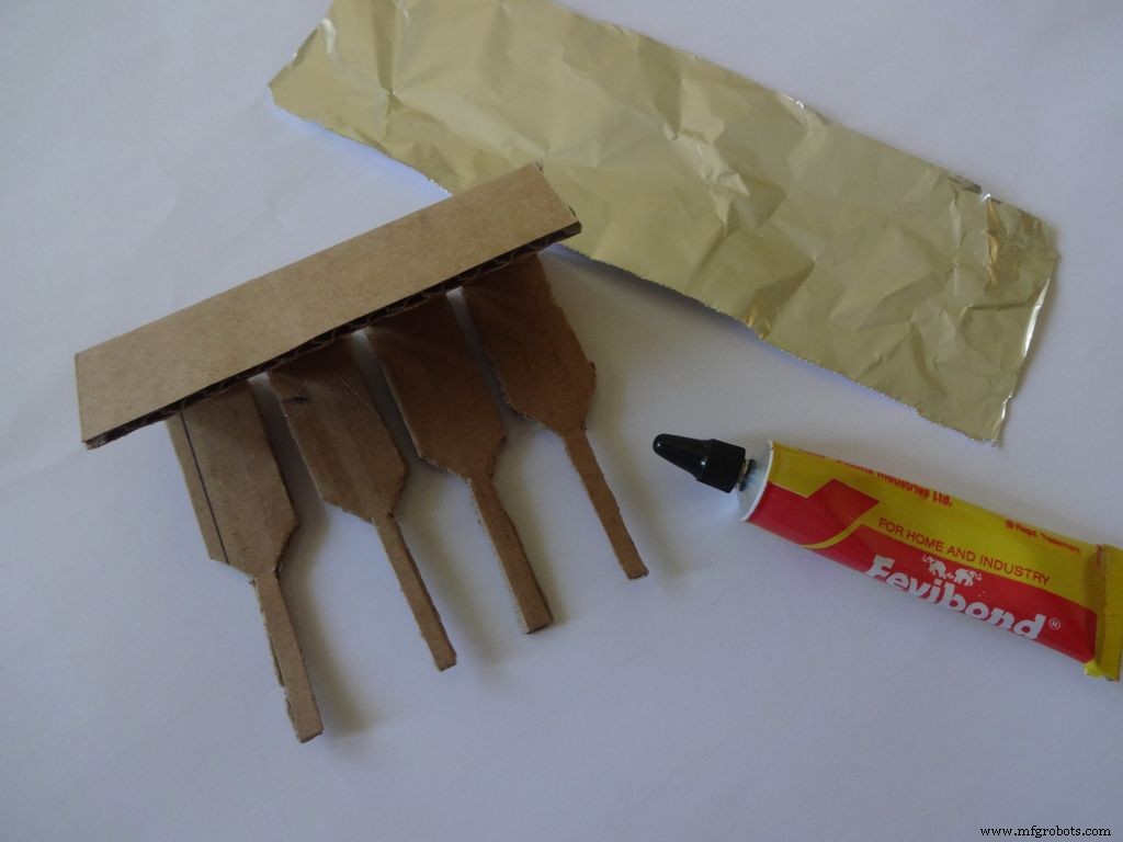
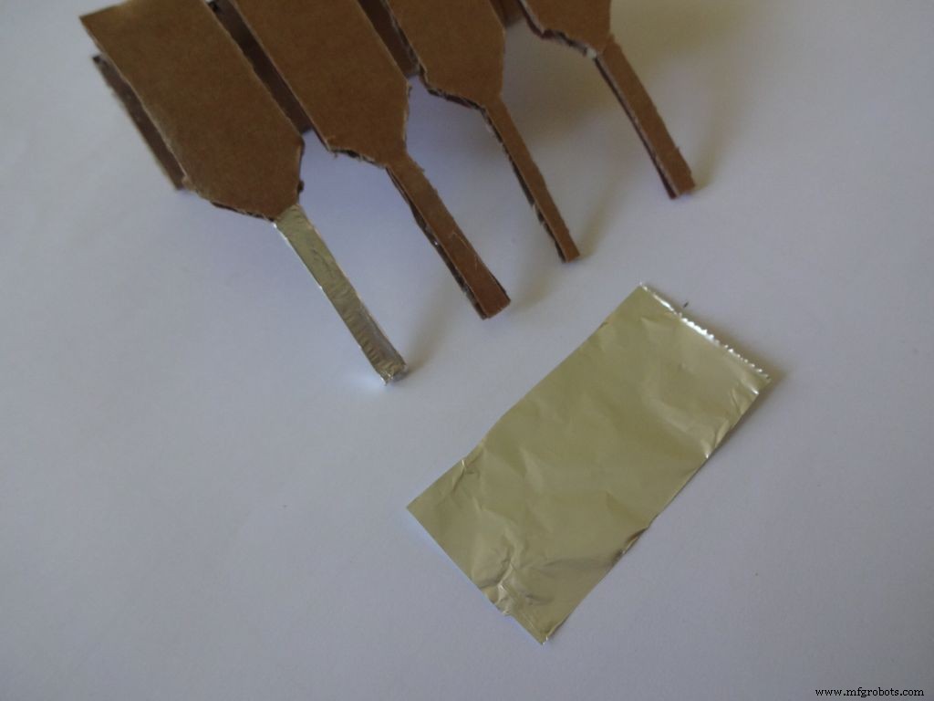
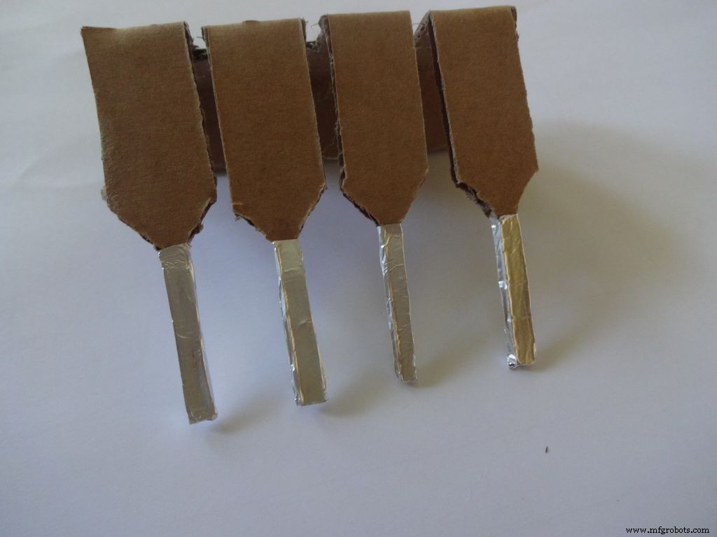
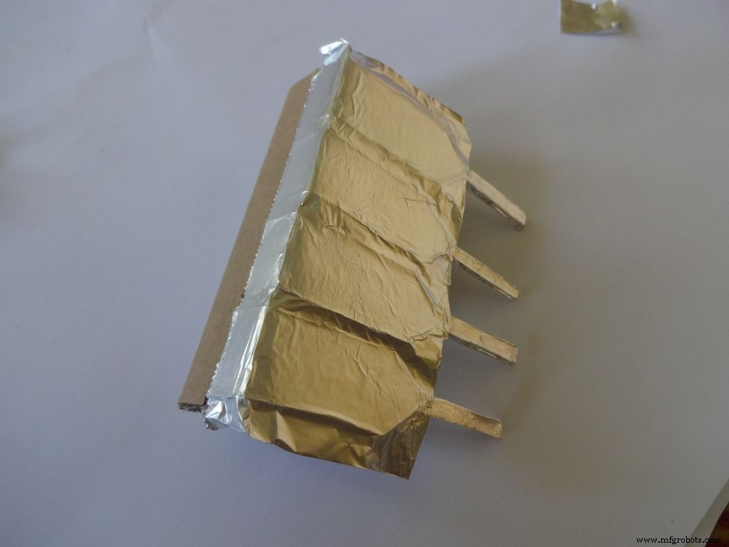
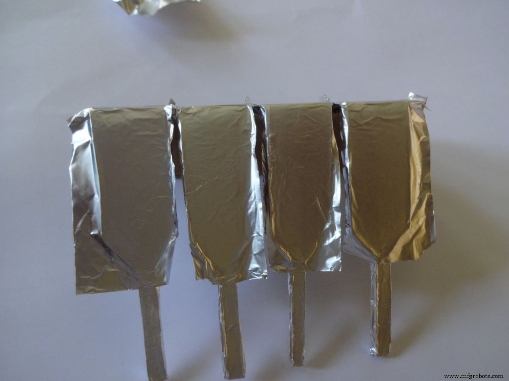
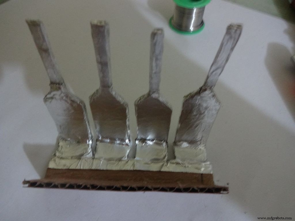
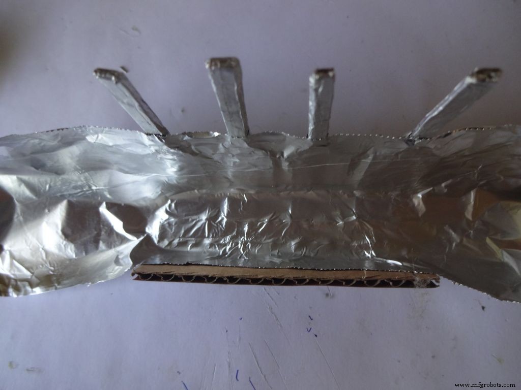
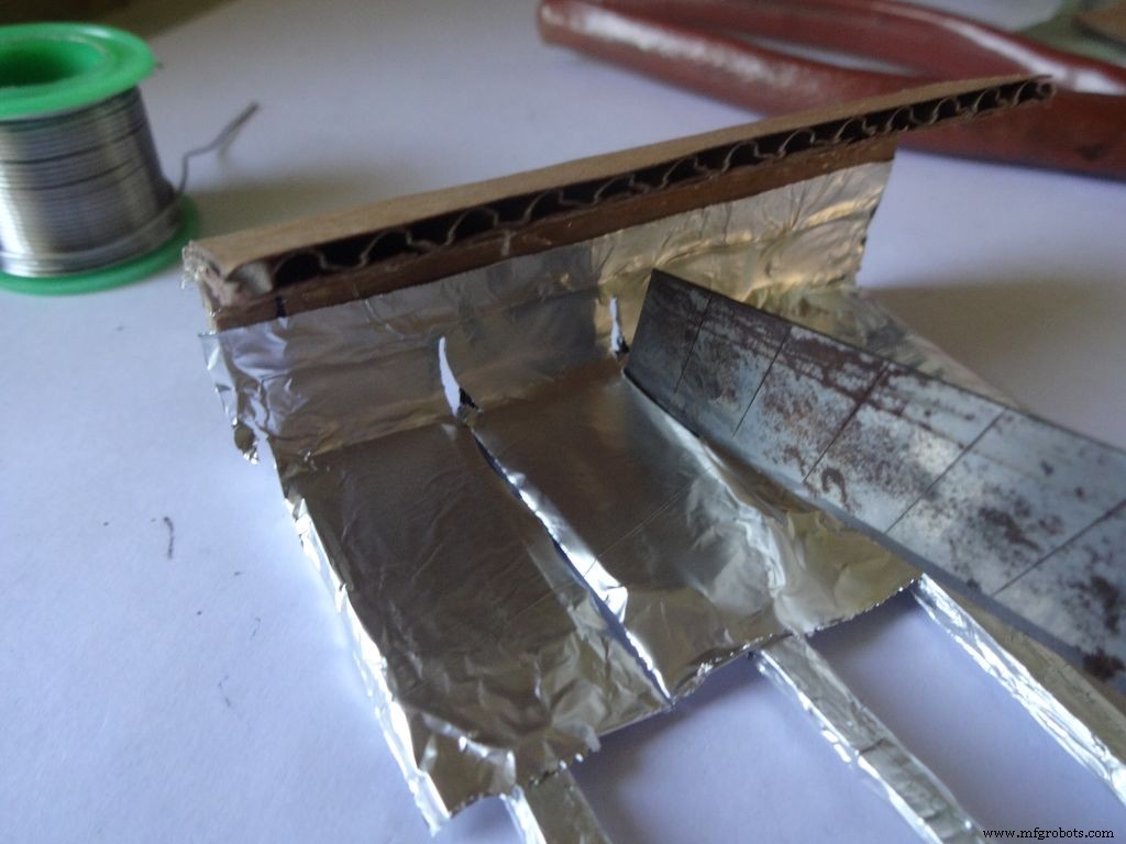
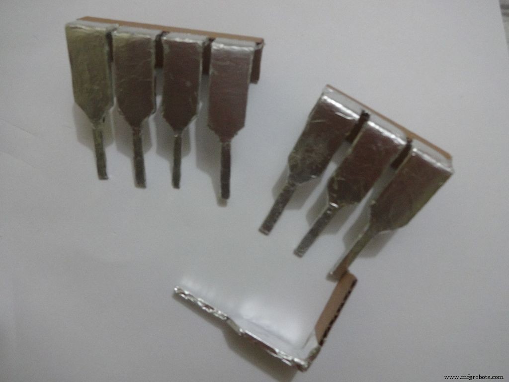

Cut a piece of foil 1x2inches and stick it carefully, fold by fold to the leg ends with some metal-cardboard sticking glue. I used Fevibond.
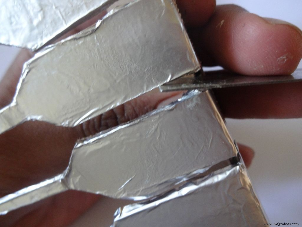
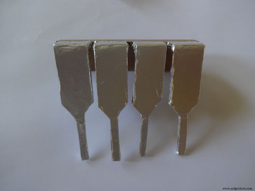
Next stick a patch that covers all the leg tops(as shown), make cuts slowly with a cutter. Do this carefully. The foil tends to tear to the sides. Use something flat to stick the foil in between the legs and give it a good finish.
Now cover it with transparent cello tape, just like you applied the foil, to protect it from sharp objects.
Step 25:The Power Switch
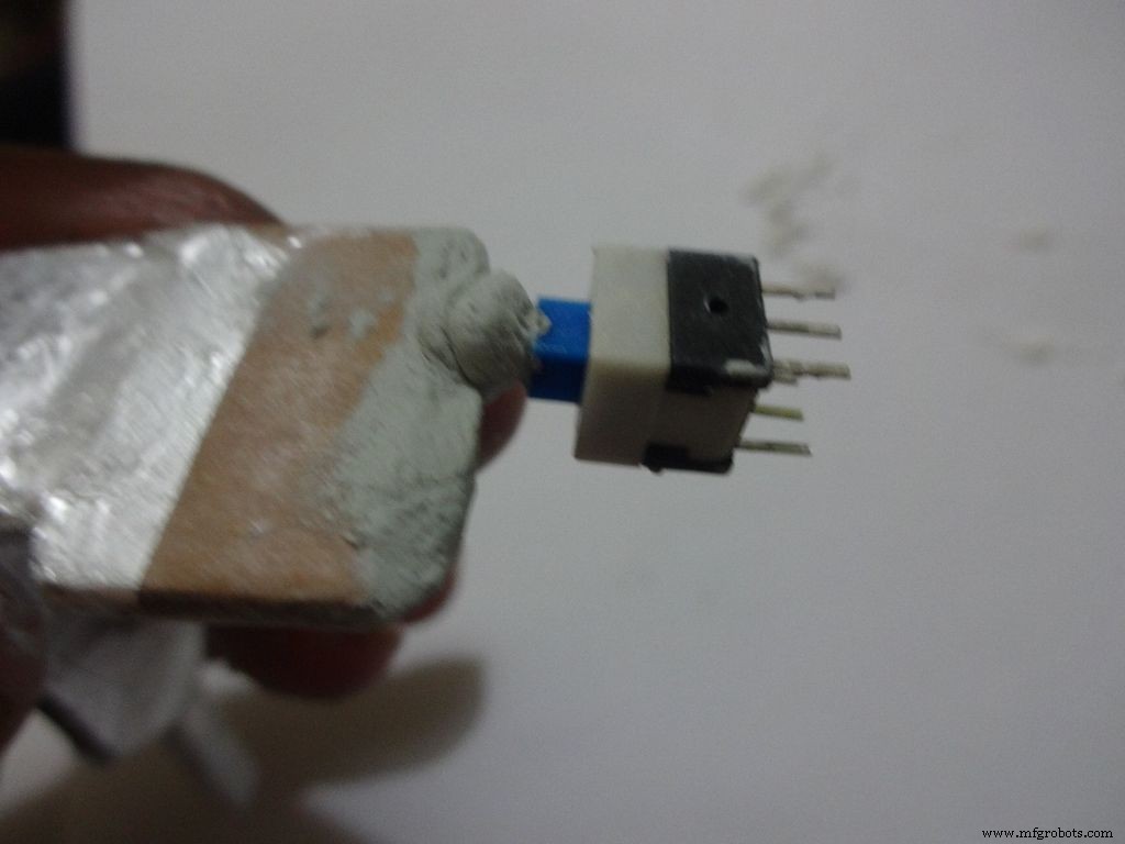
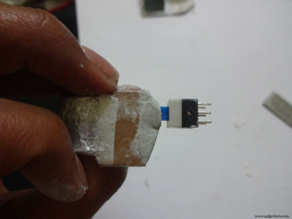
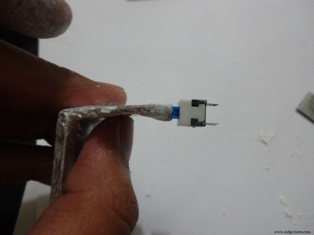
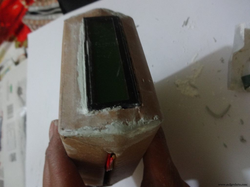
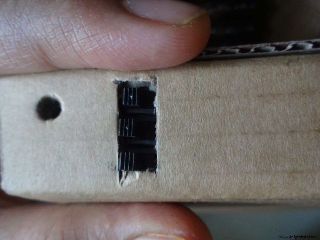
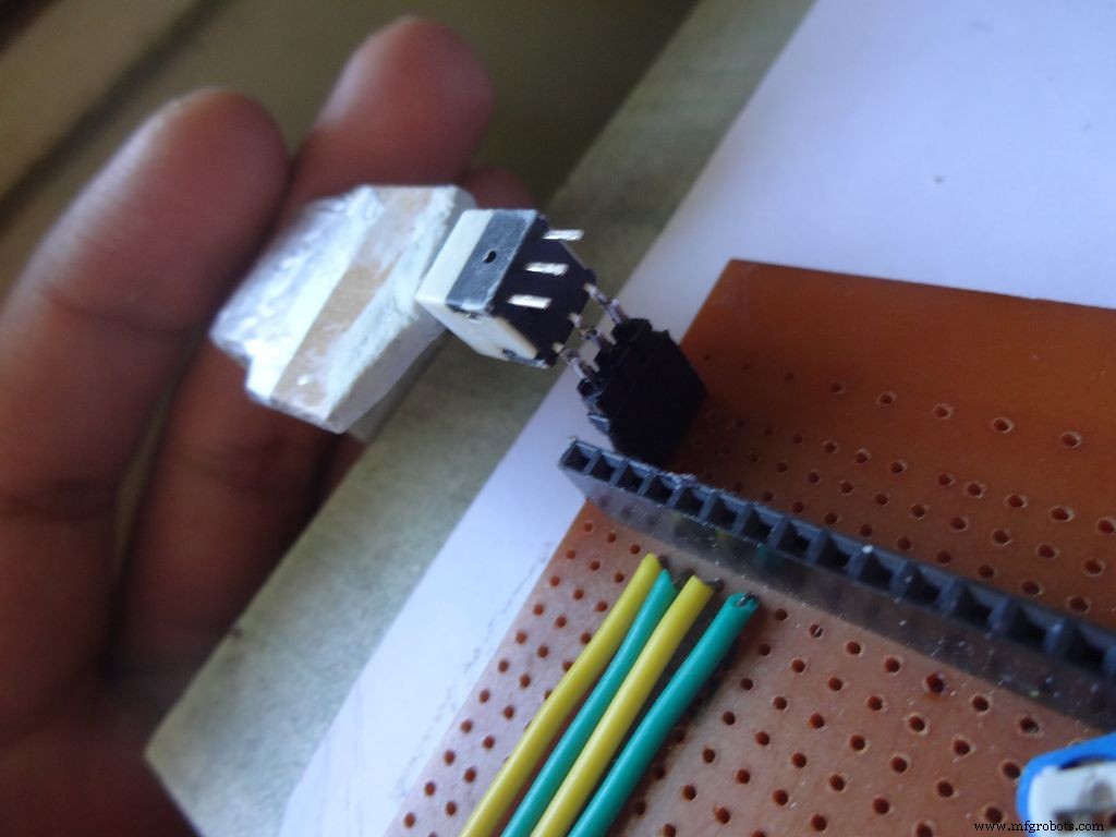
Measure and cut the power switch leg by properly keeping it in place. Temporarily stick the other pins with tape to get the pin1 position right.
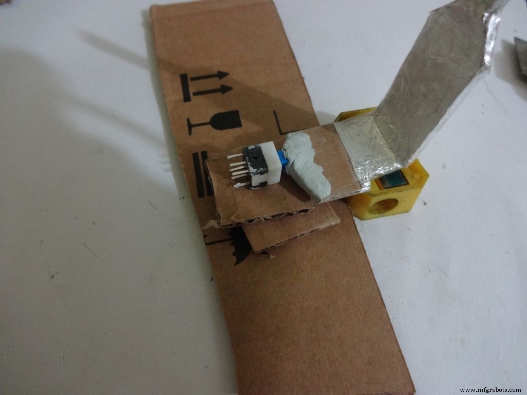
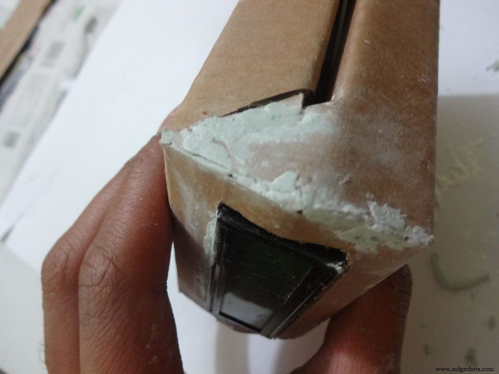
Mix the m-seal(epoxy putty sealant, gets very hard when it dries) well. Put it as shown in the images and use powder+flat surface to shape it. Let it dry.
Also fill any gaps left in your case.
Note:We cant use hot glue here as it is rubbery and the switch needs to be stuck with some strong brittle material.
Step 26:Power switch to PCB

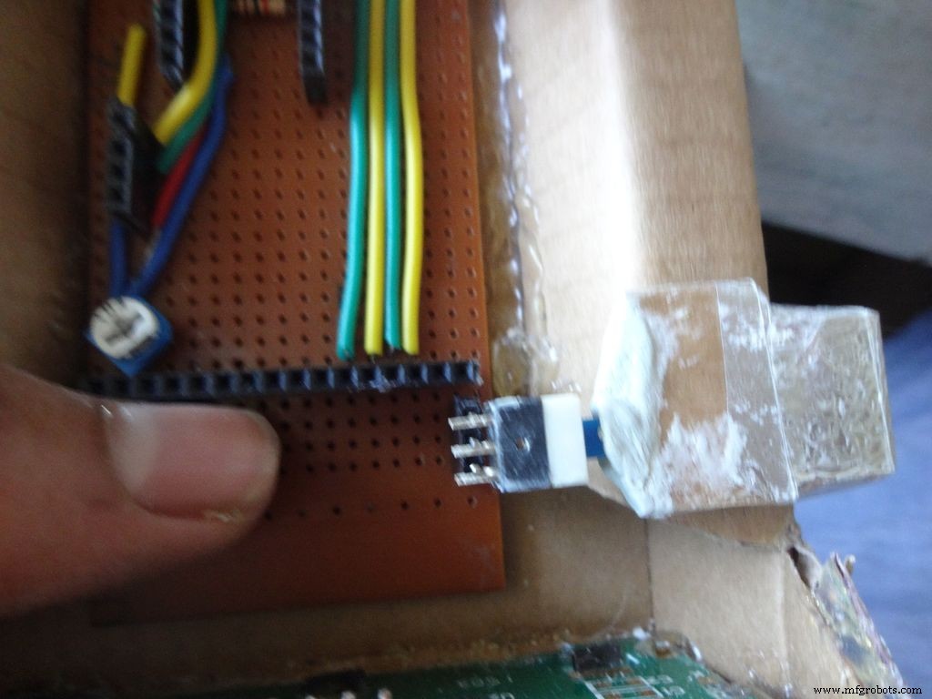
After The m-seal dries, place it in to check if everythings alright.
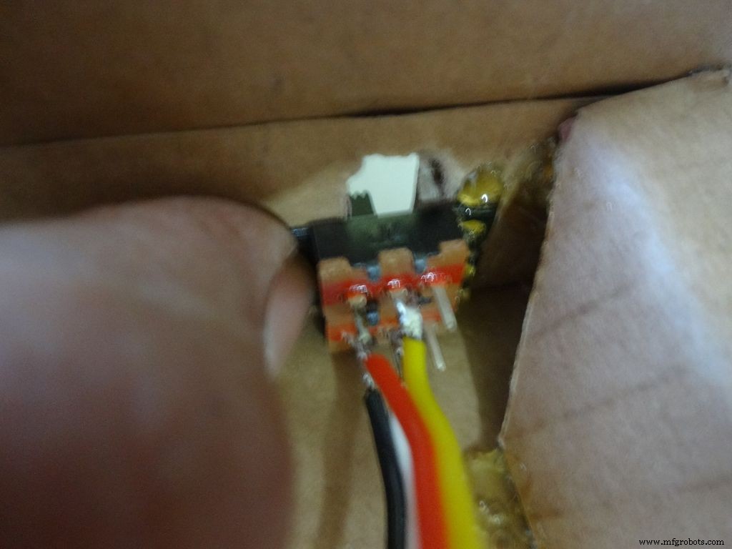
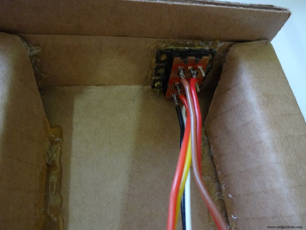
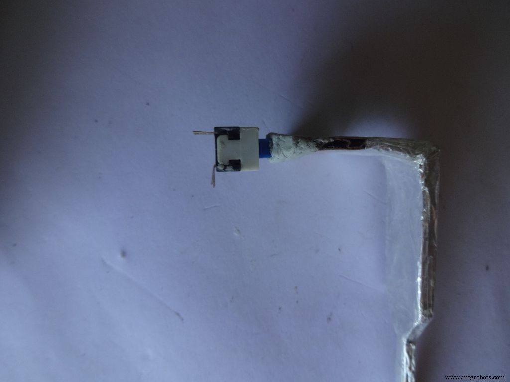
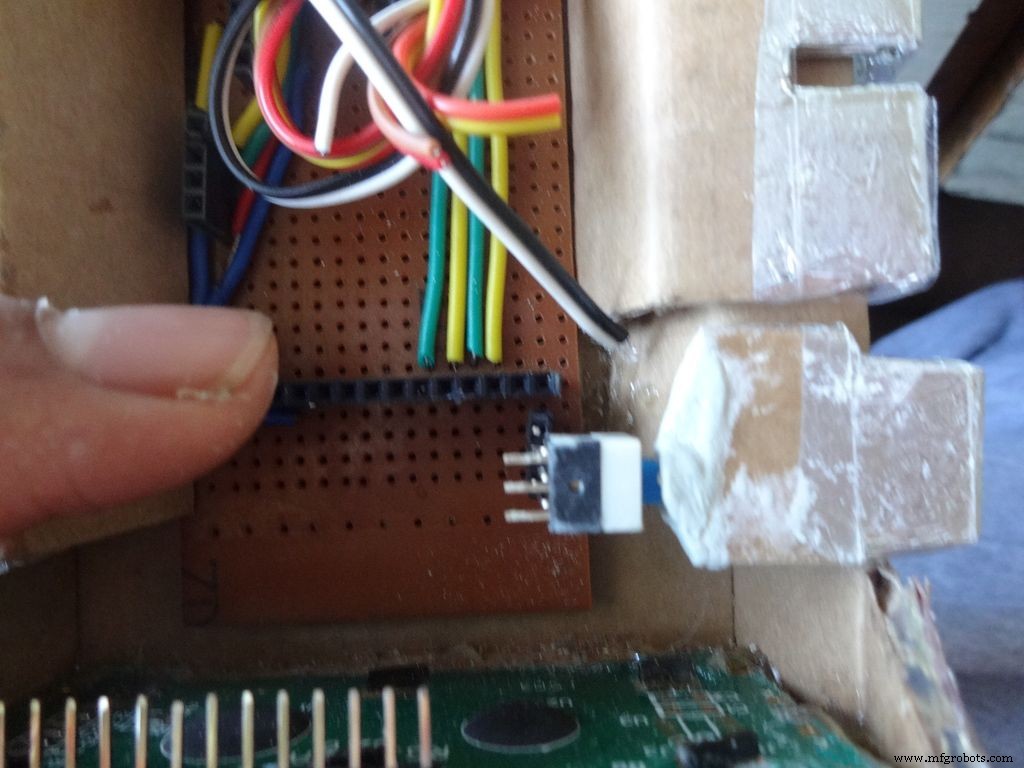
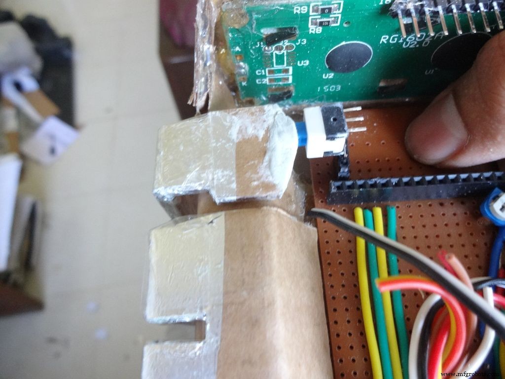
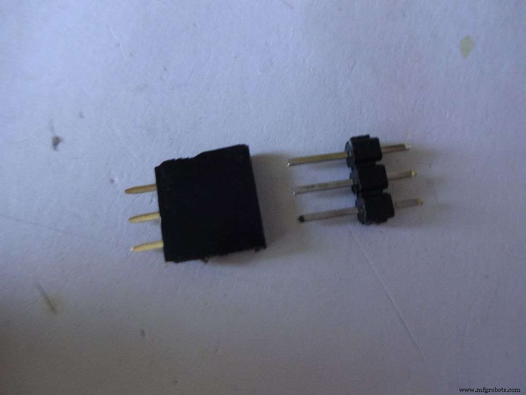
Cut 3pins of female and male headers place it on the PCB such that it aligns with the switch pins. Solder the female part.
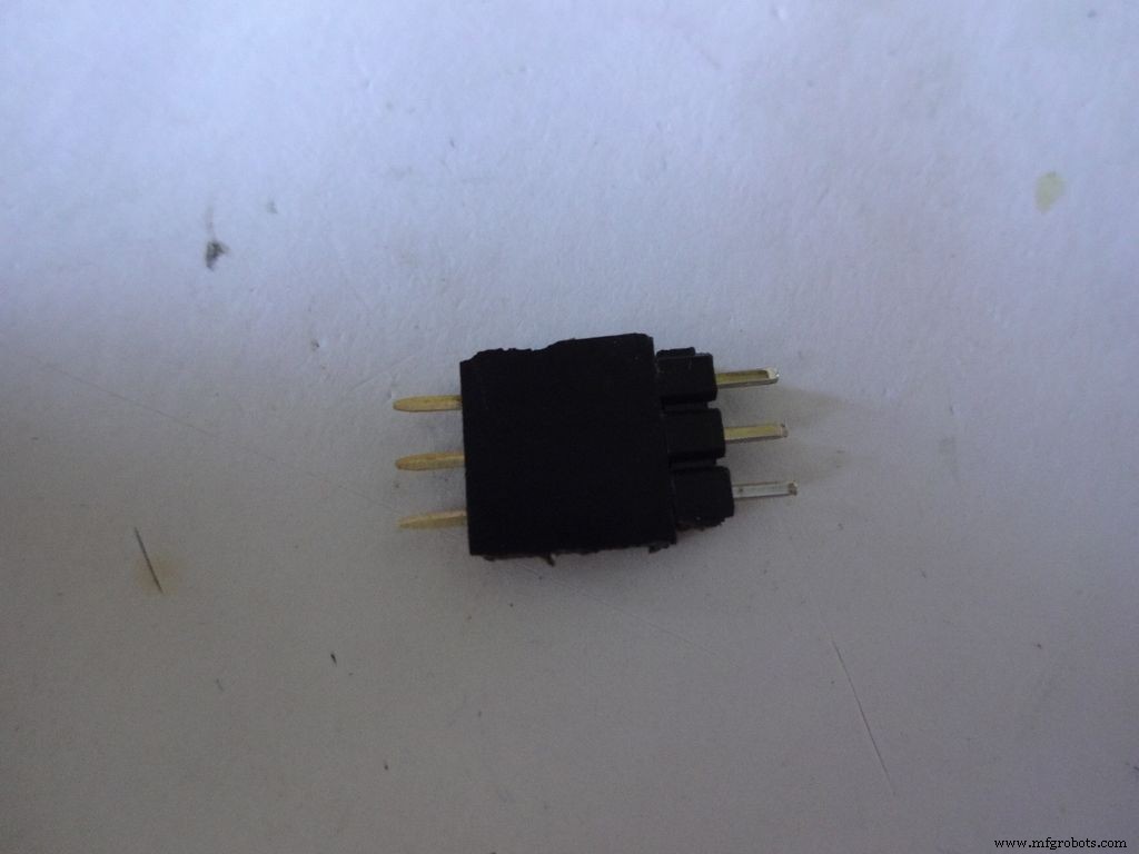
Tin the switch leads and the male header pins, join them. See if it fits at the right place.
Try pushing the switch on and off after placing a finger behind the switch for support. We will add a support rod later on.
Connect a side pin of female header(power switch) to Vin. I realised this late and had to undergo lots of trouble.
Secure the header Pin with hot glue.
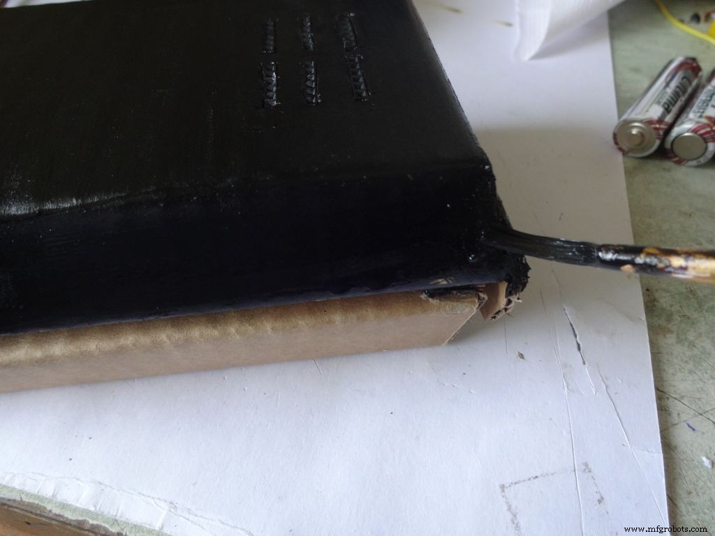
Step 27:Making the USB Port

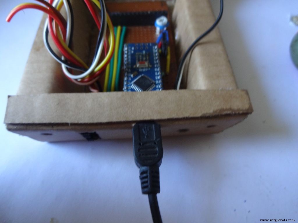
Put the PCB properly in (with Arduino) and cut a rectangle for the mini USB port.
Remove some plastic from the USB cable so that it fits the Arduino properly. Test whether connection is proper.
Step 28:Some other things...

I removed all the LEDs from the Arduino Nano and also the power LED on my RTC module. These consume unnecessary power, which matters if you are operating on a battery.
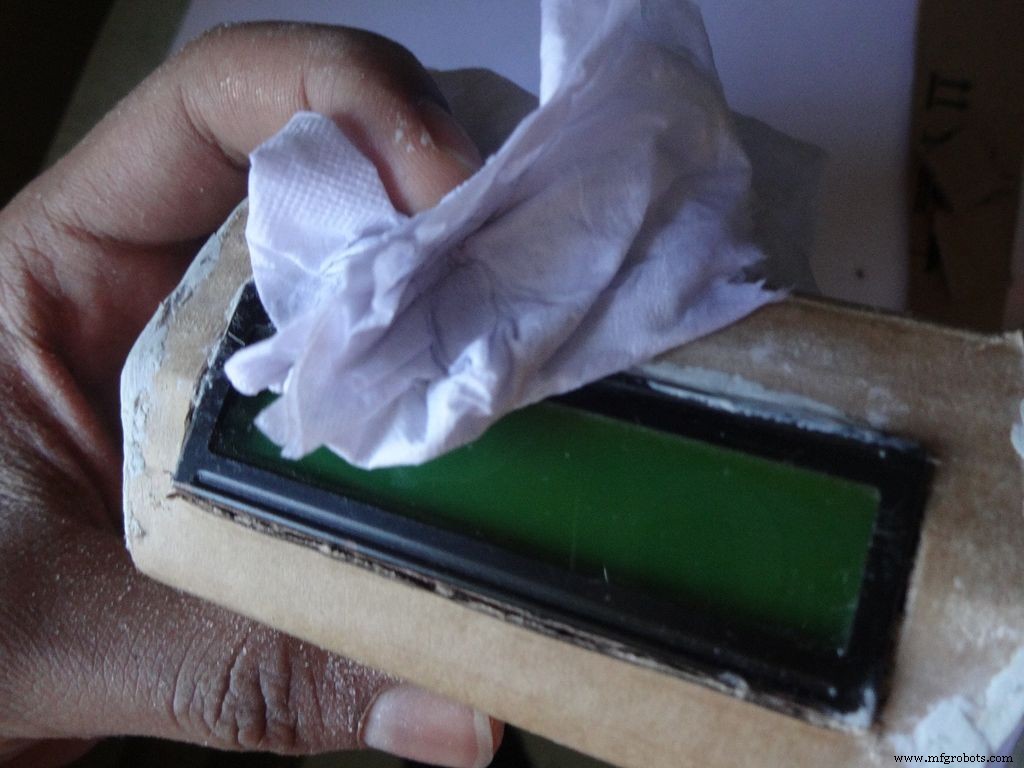
Sand the dried m-seal so that it mixes smoothly with the cardboard. Clean the powder with a wet paper napkin before painting.
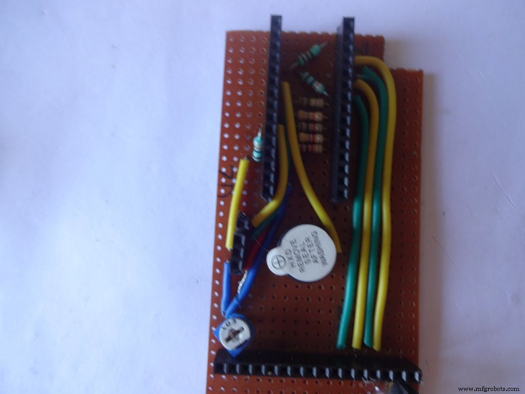
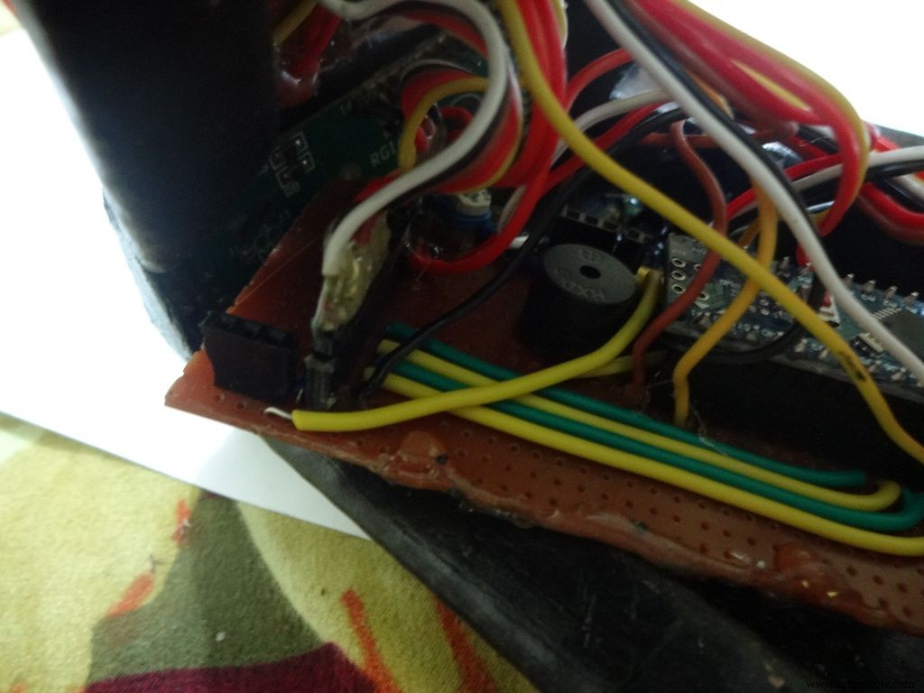
I also added a buzzer which may be used for some functions. Buzzers are sensitive, don't use too much heat while soldering!
Step 29:Time to paint!
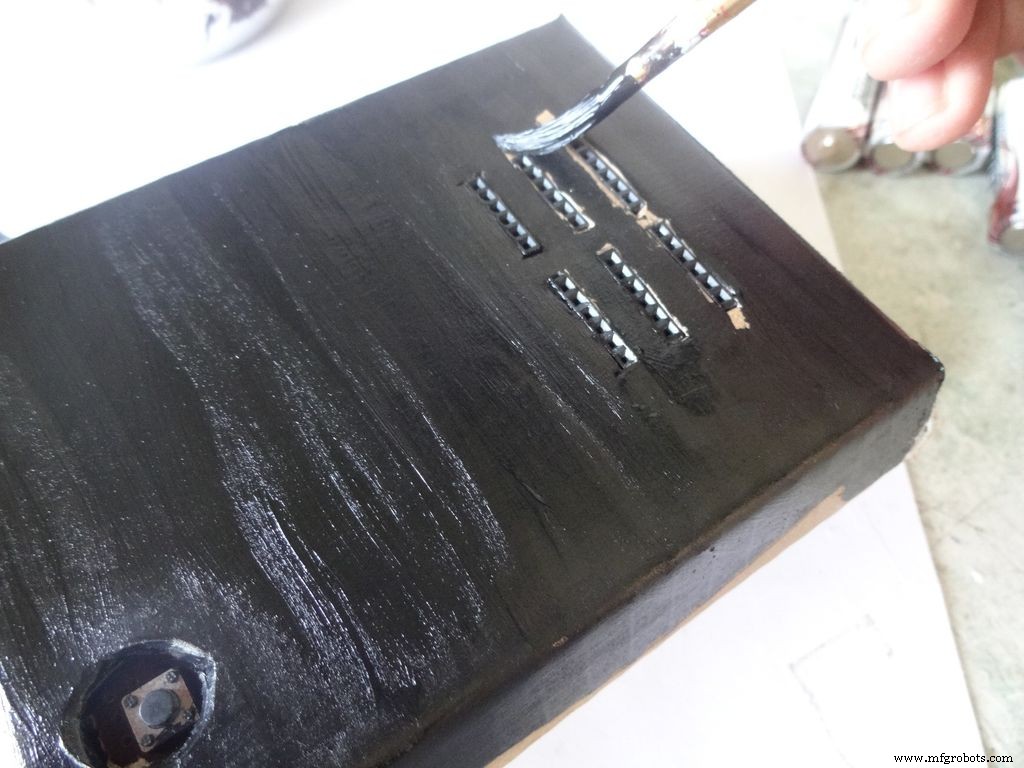
Dont use direct thick paint while painting, this cases brush patterns to appear. Use sufficient water.
Make sure no tiny bubbles are formed. These form when you dab the brush too much.
Dont paint the cover hinge, the paint will restrict it.
This is just a base coat. Another layer of paint will be added while finishing up.
Step 30:Soldering all the wires
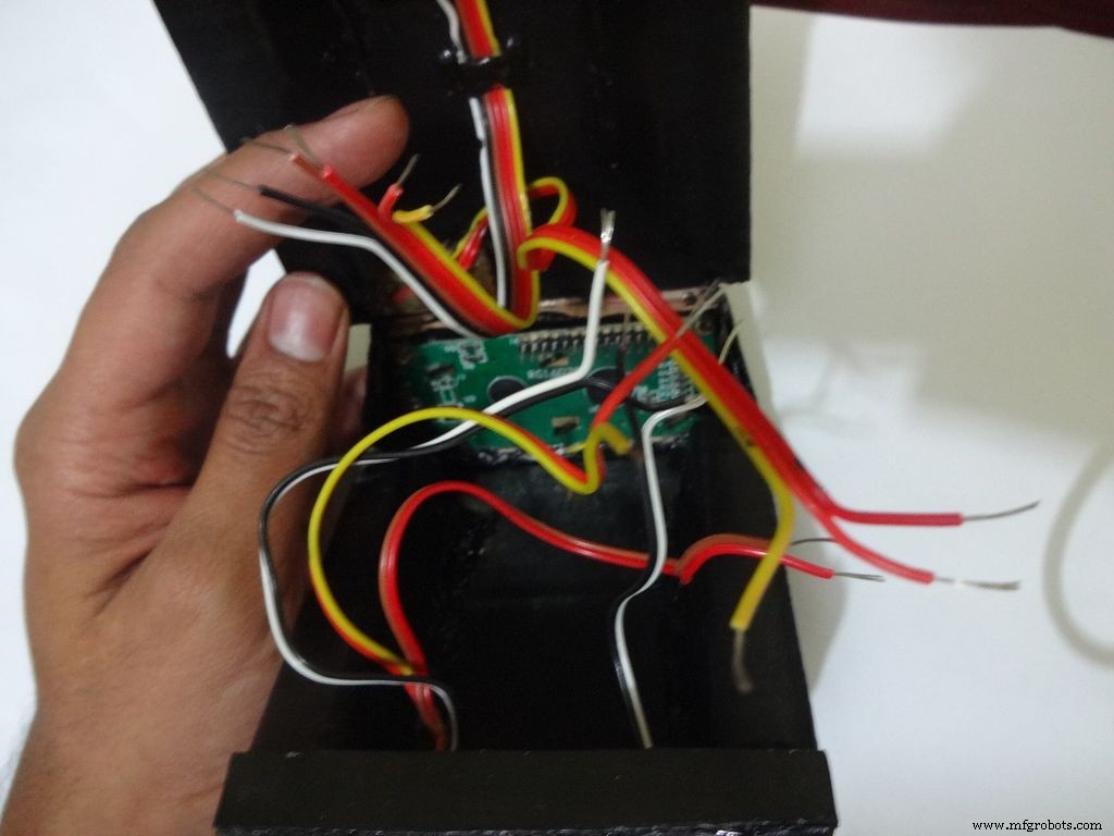
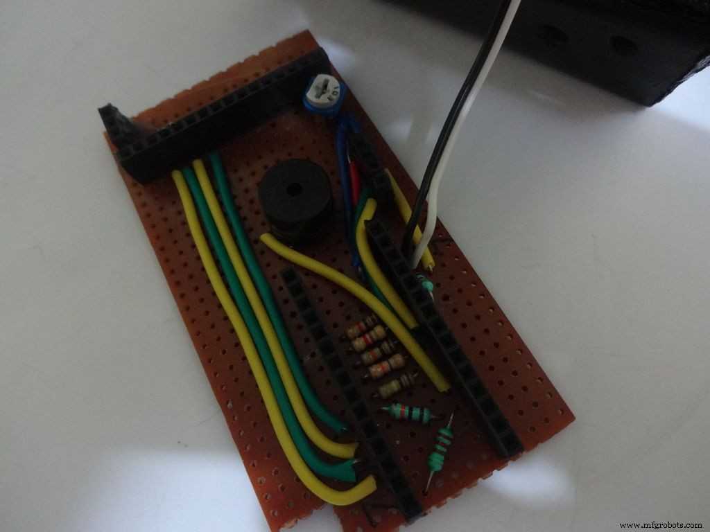
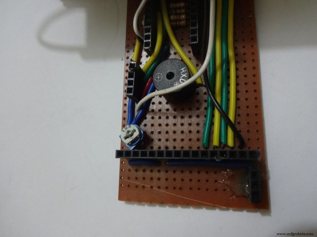
Make sure you refer the circuit design before making any connections.
First connect the reset switch, one end to RST and one end to GND.
Then, the backlight switch. One end to +5V and other end to 'A' or Anode of the backlight LED. Also connect 'K', Cathode to GND.
Next is the RS switch, connect one end to RS and other to pin D1(TX).
And finally the Enable switch. Connect one end to 'E' or Enable and other end to pin D0(RX).
Switches
Where to?
Reset - pushbutton RST and GND Backlight - slide +5V and A RS - slide D1 (TX) and RS Enable - slide D0 (RX) and E
Note:Pins D0 and D1 are connected through switches as keeping them connected sometimes causes problems while using Serial(for debugging).
This completes the base wiring. Apply hot glue after double checking the connections.
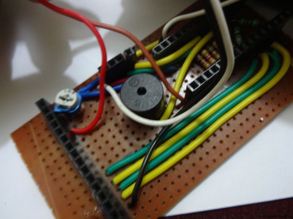
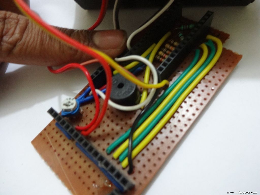
Then connect the 3 wires of mode change button:The 10k pulldown resistor to GND. 220 Ohm resistor to pin D11 and input pin to +5V or VCC
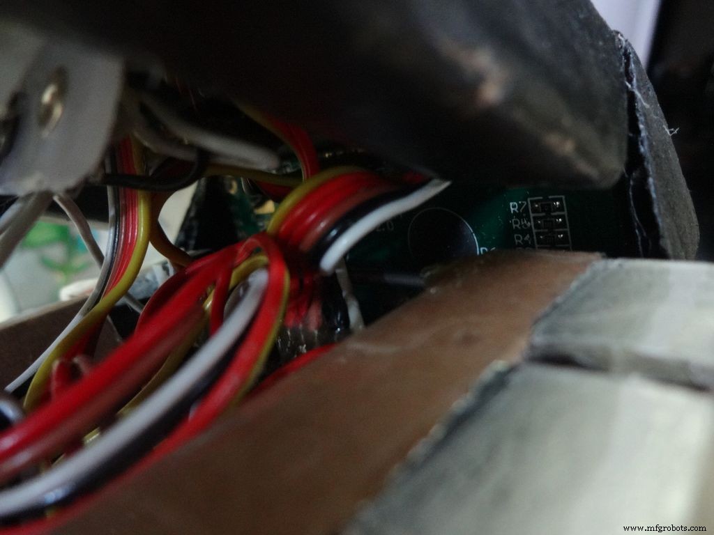
Finally connect the 6 wires from the test slots to their appropriate places(shown in images).
Positive
Negative
Resistance Test A7 GND Capacitance Test A0 GND Diode Test A6 D12
Note:All the +5Vs and GNDs are same and hence connect to most convinient spot.
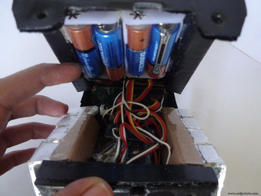
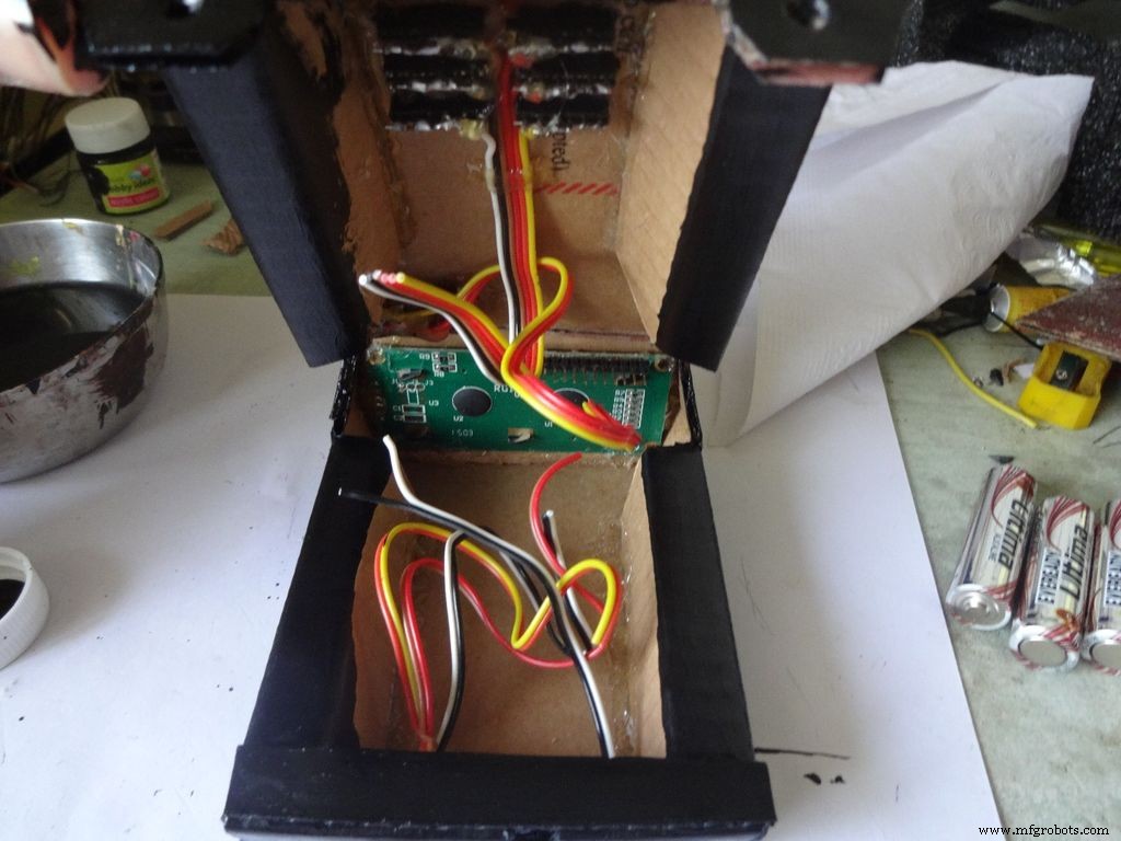
Step 31:Adding the battery case
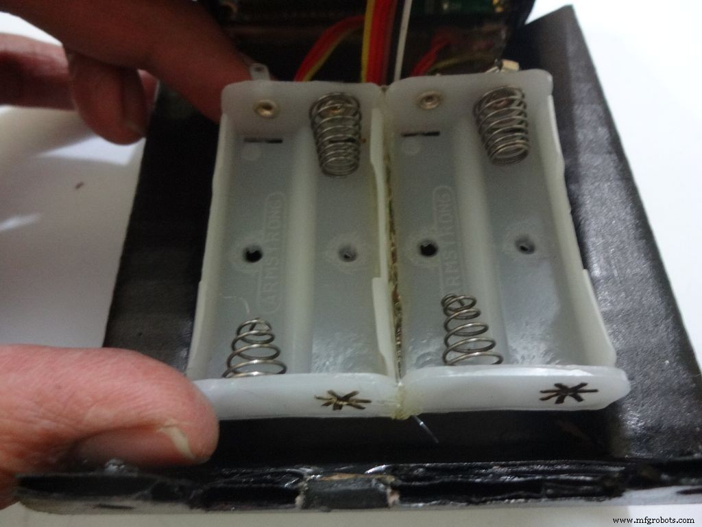
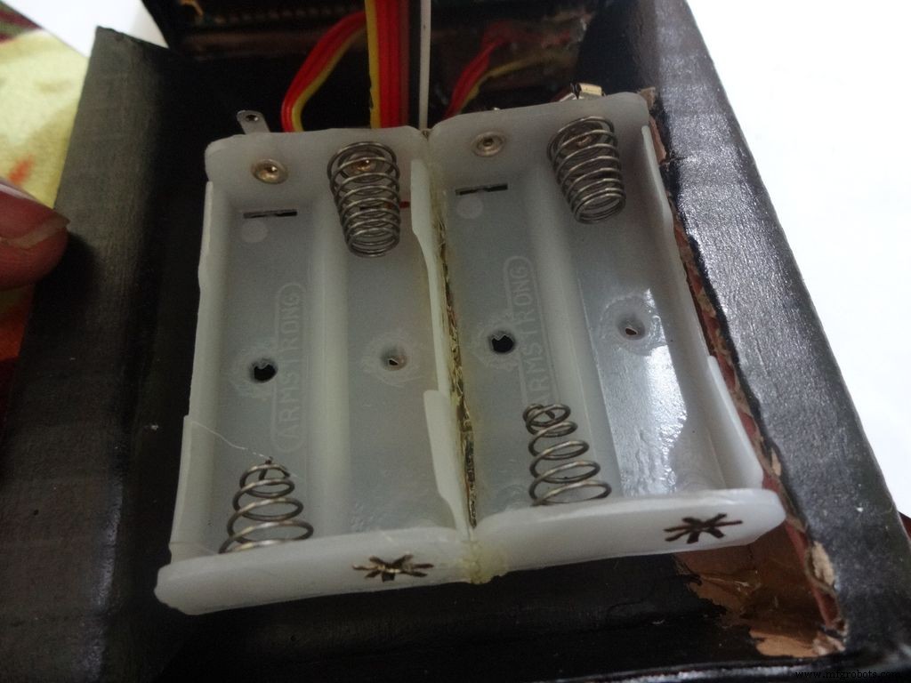

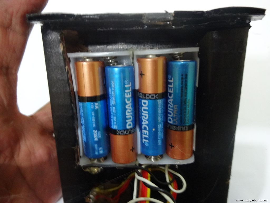
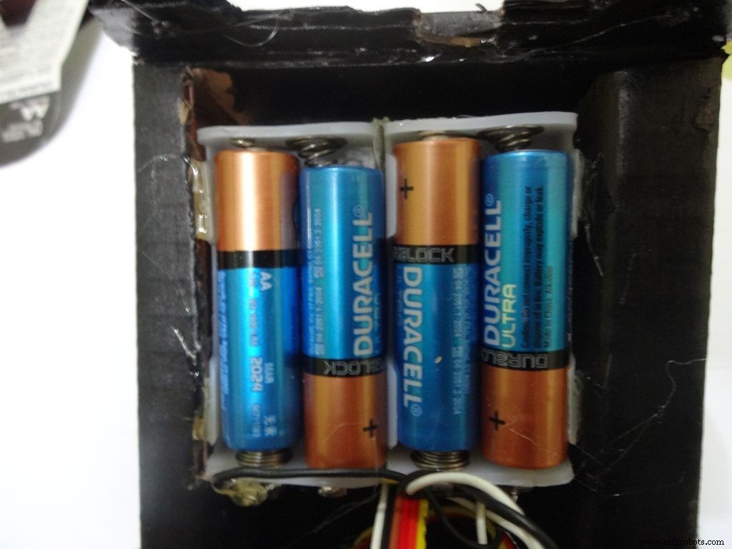
Place the battery case at the top cover, make cuts to place it inside such that the cover can be closed properly.
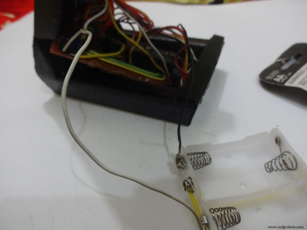
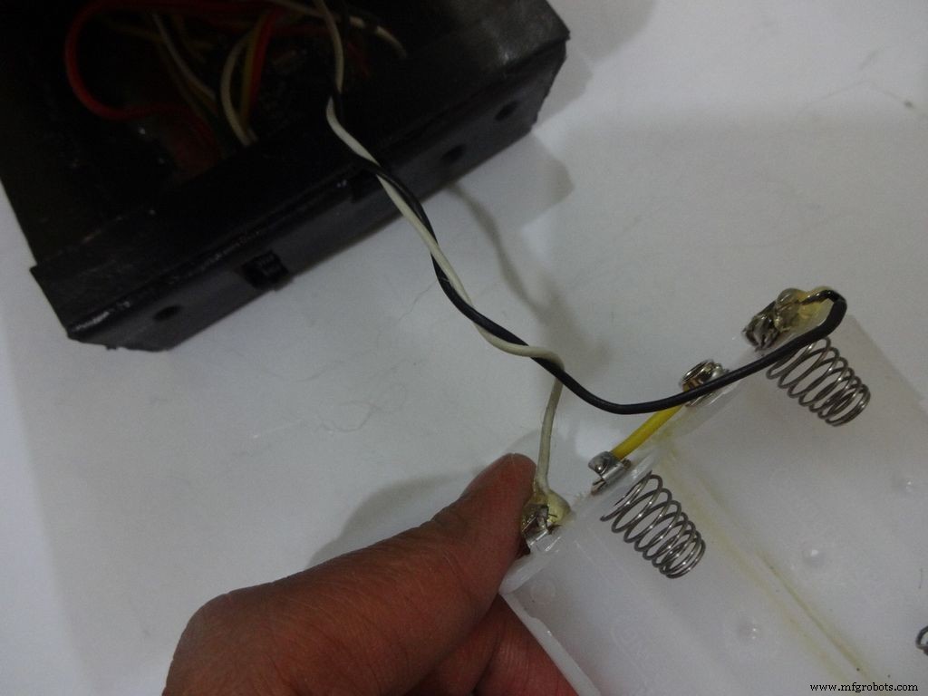
Solder Wires to the case, strip and tin them. Solder the positive end to the middle pin of power switch and negative end to ground.
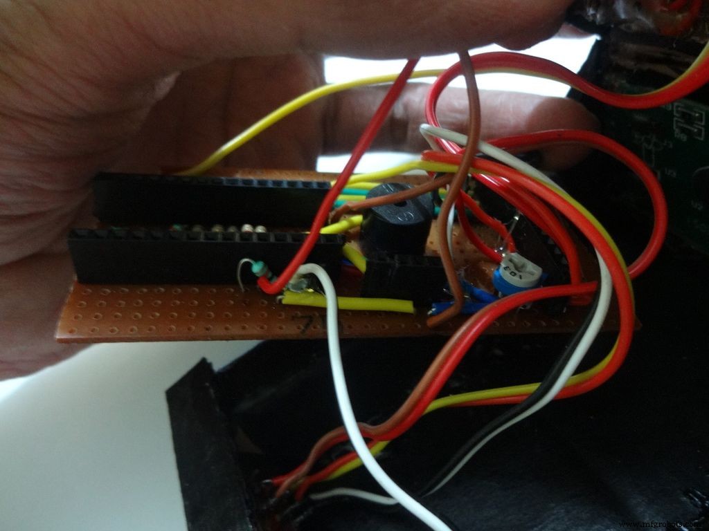
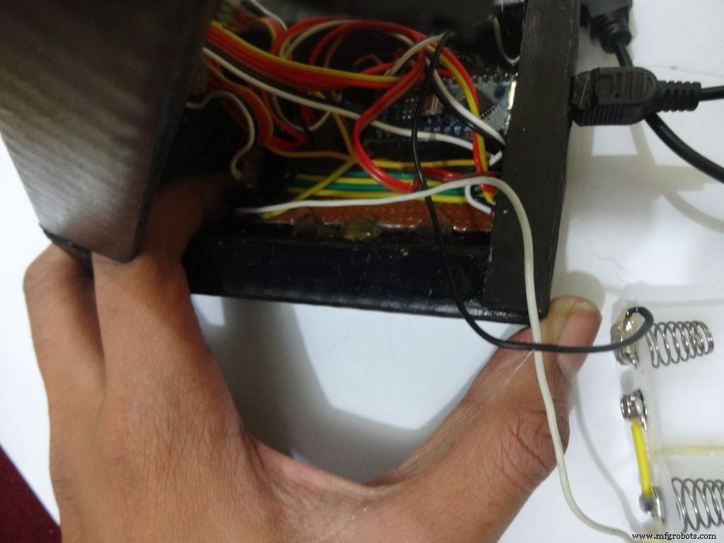
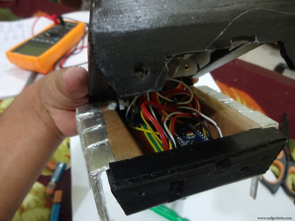
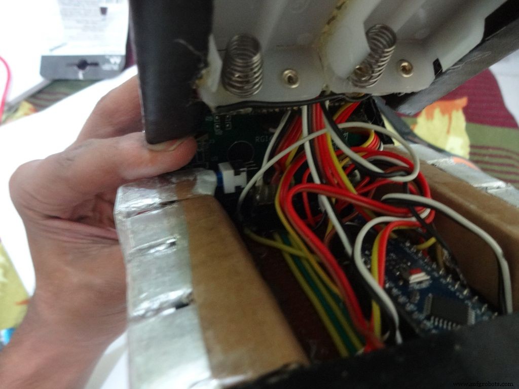
Glue the PCB to the base after making all the connections.
Twist the wires and place them in position. Insert batteries(the case expands a bit on inserting batteries) and glue the case to the cover.
Step 32:Adding the Legs
Cut the inner part of legs so that it fits in properly. Stick it it place.
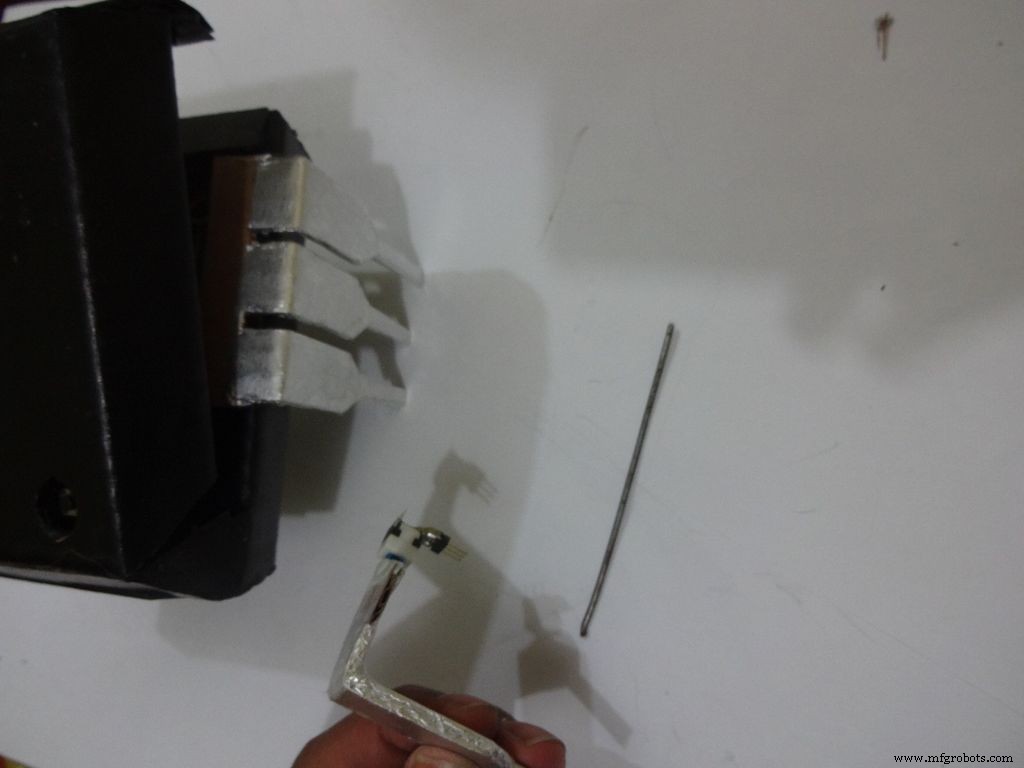
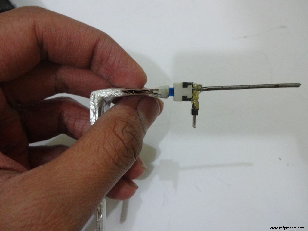
Put the power switch pin in to check if it fits in perfectly. Remove it, add a metal rod, piece of wood or anything strong of proper length that will prevent the switch from moving back. Glue it in place.
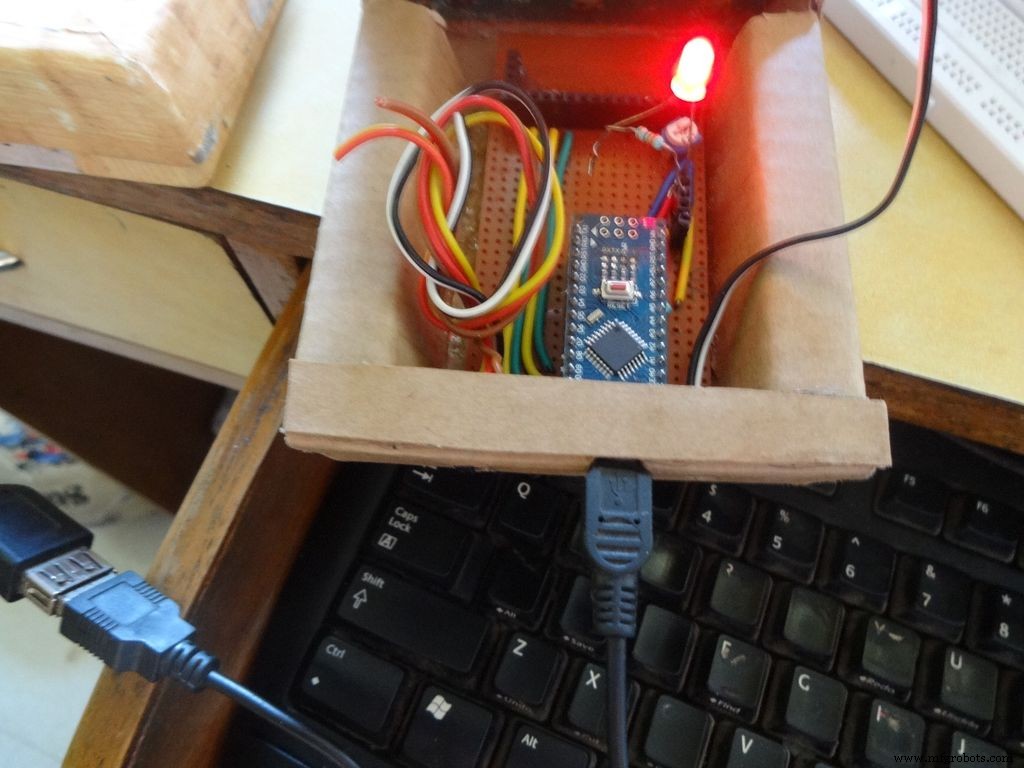
Check the switch, it should be turning on/off smoothly.
Switch on the IC and test all the functions. If its not working skip to the troubleshooting section.
Step 33:Finishing up!
Use M-seal (or equivalent) to fill any small gaps around the testing area and the mode change button. After drying, sand it well and apply a second layer of paint.
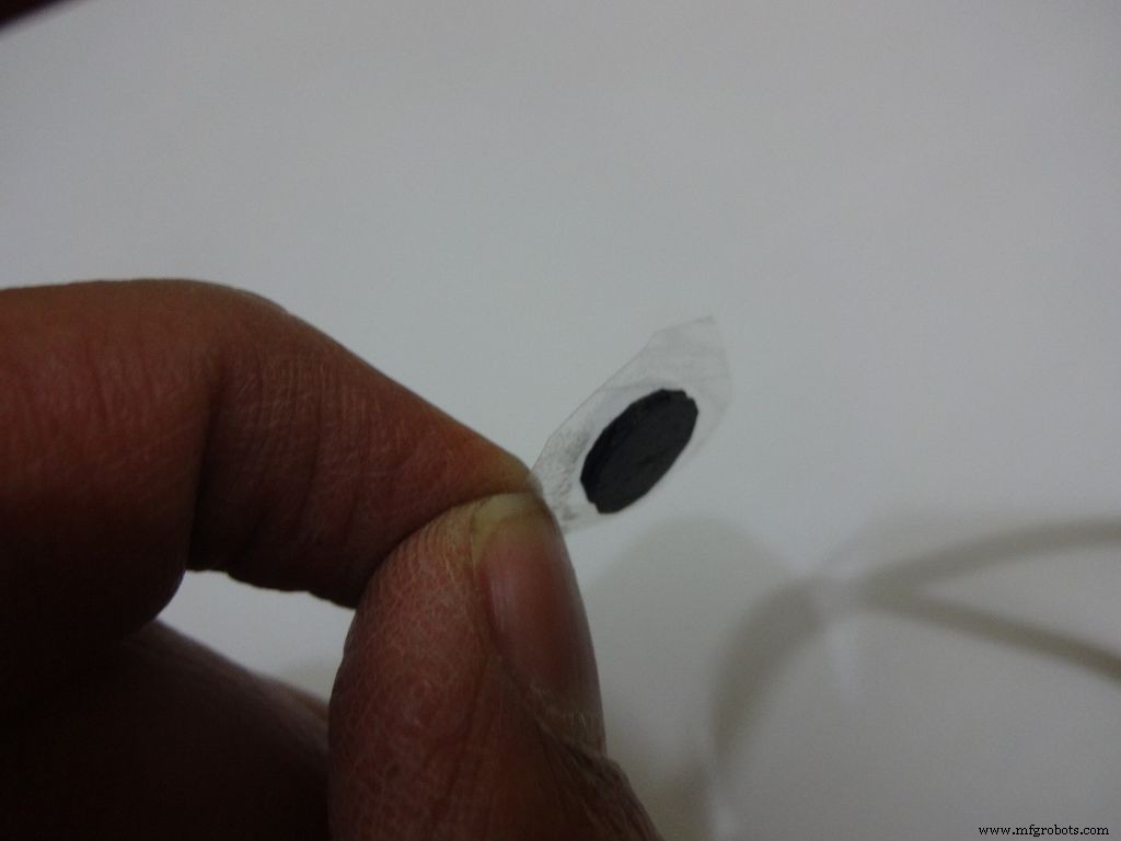
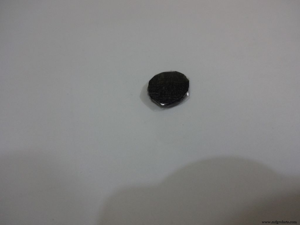
Make the button with a small piece of cardboard, paint it black and cover it with tape(gives a shiny finish). Apply a tiny drop of glue and stick the button in place.
Step 34:Problems and Troubleshooting

Do everything correctly. This is the most boring most of any project and you dont wanna get here just because you soldered the wrong pins!
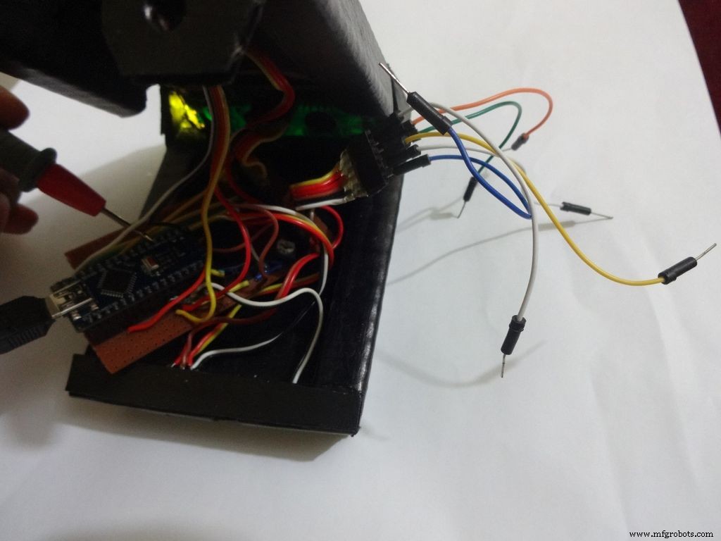
- Recheck every soldered joint and ensure that it isnt touching the adjacent one. Use the multimeter continuity test for help.
- After cutting component/jumper leads make sure the cut lead doesnt fall underneath the PCB. This may lead to unwanted shorting soldered joints.
- Write down anything you need to remember in a book, don't trust your memory.
- If LCD is not displaying, make sure the contrast is adjusted properly. Also make sure the pin0 and 1 switches are turned ON. Check all the pin connections from LCD to Arduino with continuity test. Use breadboard jumpers wherever your mutimeter cant reach.
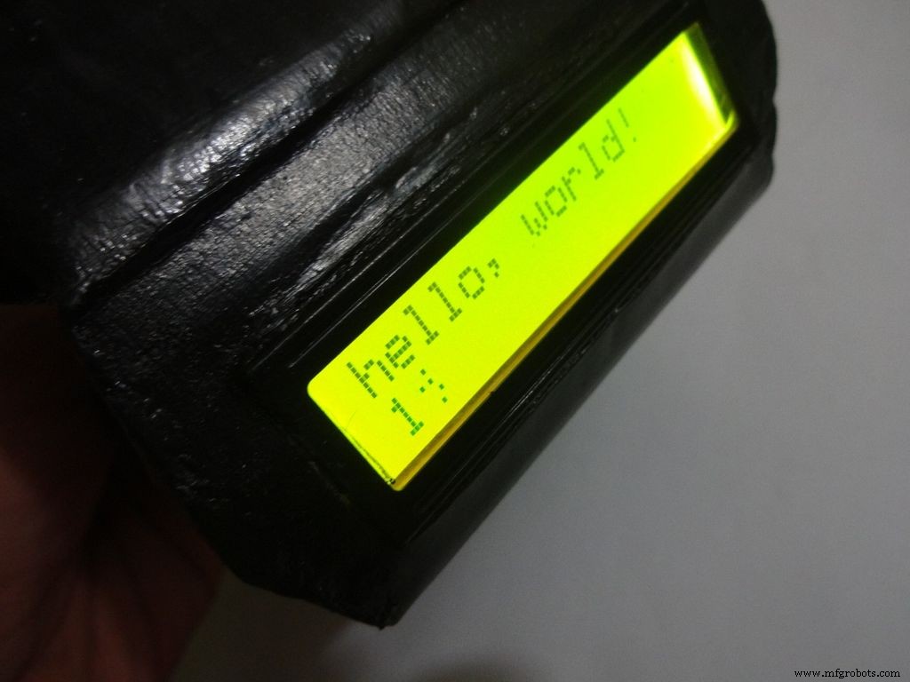
- Upload the hello world LCD program to see if the problem is in the code.
- If a particular function is not working, check its connections and tally it with the code.
- And most importantly, keep your curious pets with their evil minds away from your workspace! :p
Step 35:Things I did, some mistakes I made
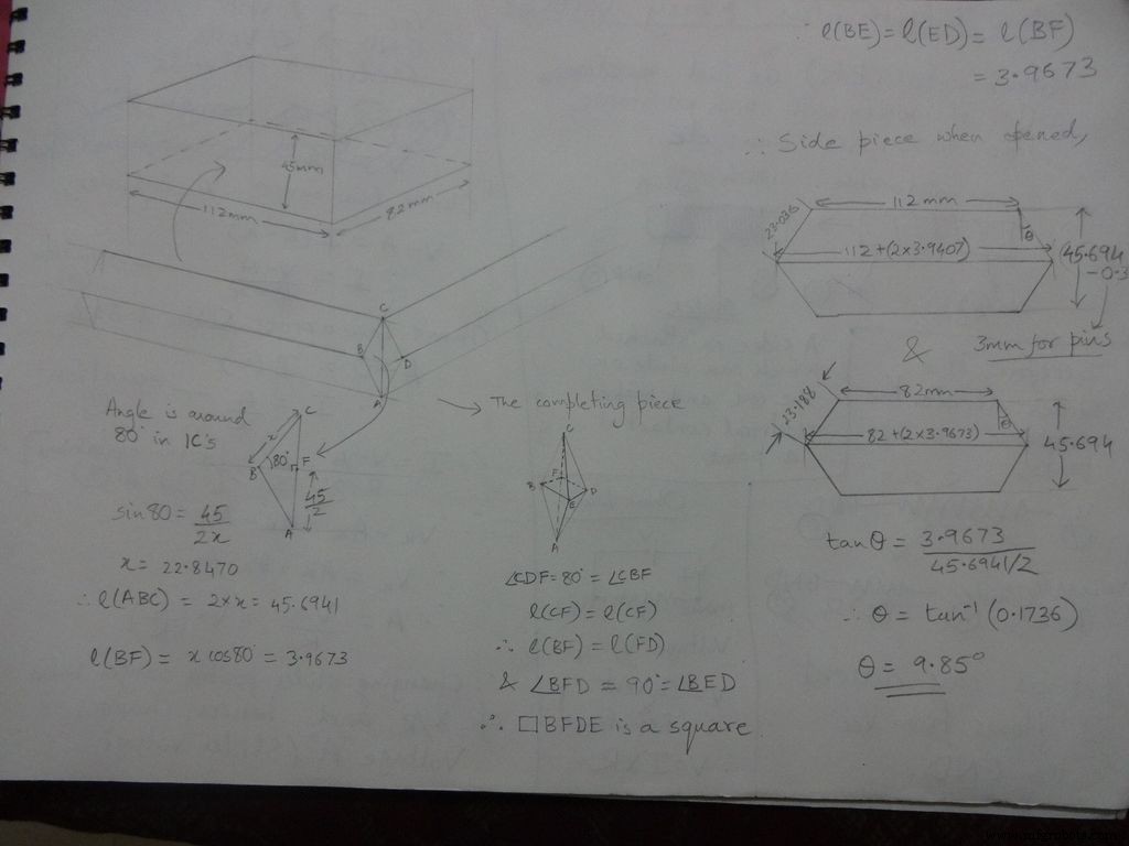

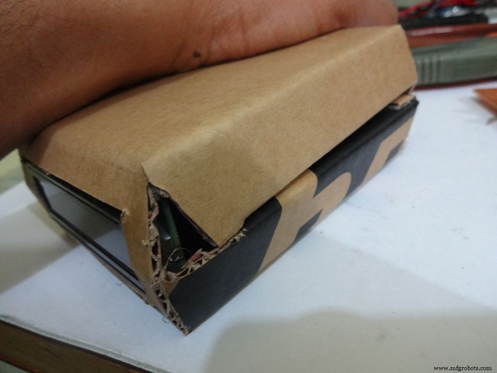
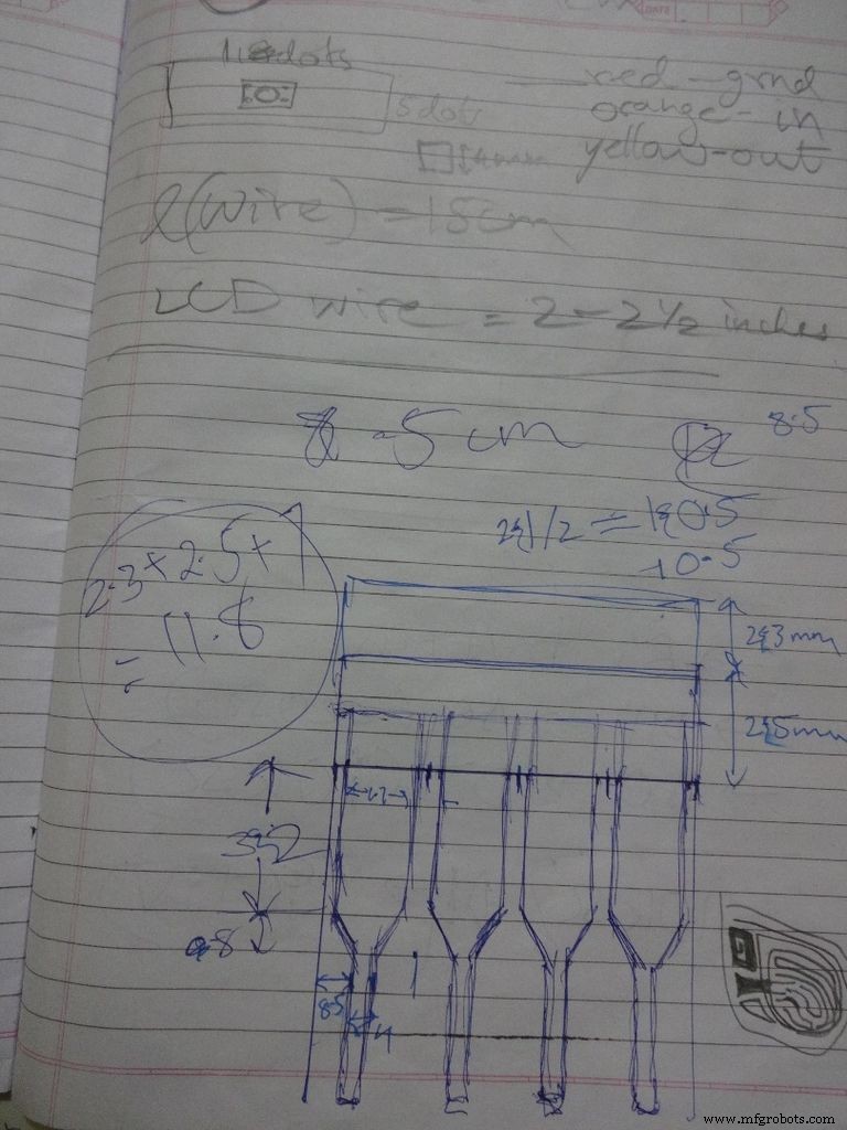
While testing the various circuits and when I had the rough idea of what I want to make, I decided to go with the IC design. I measured actual ICs, took ratios of their lengths, got the angle with some trignometry to be around 80 degrees. Then I decided the inner box length and breadth and built upon it(shown in image). Once the layout was planned, I initially started to draw it accurately on a large size paper. After a bit of a struggle of drawing accurate lines, I realised that this kind of work should be done on a computer! So I learnt CAD basics and succesfully made the layout on it. :) But this layout didnt work out and I had to redo the entire cutting and making of the case.(See images)
While removing the LEDs on the Arduino Nano I used excess pressure to remove a stubborn LED, and ended up removing a PCB pad. Always desolder without forcing/applying pressure on the joints, the pads are delicate and easily come off if you dont stay calm.
When all the solder joints were made and project was about to get finished, in excitement and eagerness, I glued the PCB inside the case before adding the battery case. Had to re-melt the hot glue with a soldering iron (carefully not to melt any wire insulation) and remove the PCB out to solder the battery case wires in. The soldering iron can be cleaned afterwards.
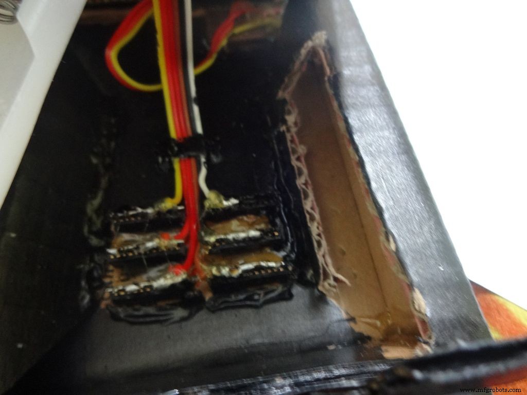
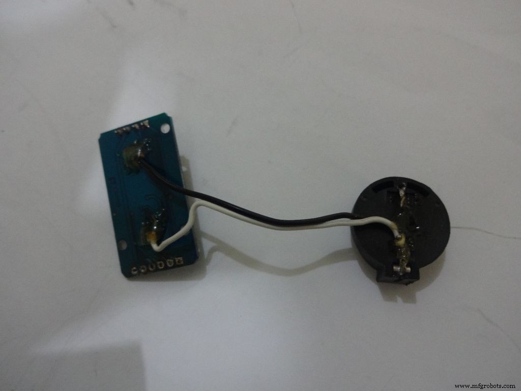
The RTC module battery was coming in way of the batteries while closing and so I separated the battery holder(Warning:desolder only with the battery removed) and added extension wires so that the battery can be placed at the sides where there is space.
All the Layout PDFs, CAD Files and the Main code can be downloaded here:Google Drive
Código
- Snippet de código # 1
- Snippet de código # 2
- Snippet de código # 3
- Code snippet #4
Snippet de código # 1 Texto simples
//Analog pin used to find resistanceint Apin=7;//values of r1 to r5float r1=1000;float r2=4700;float r3=10000;float r4=47000;float r5=100000;//pins of r1 to r5int r1_pin=2;int r2_pin=3;int r3_pin=4;int r4_pin=5;int r5_pin=6;float reading=0; //read from analog pin and store herefloat R=0; //calculate unknown and store hereString finalR; //final value to be displayed along with unitsint caseno; //for debugging, stores the case number // we divide the entire range into cases and assign each a number, // total 5 cases // case1 :less than 2850 // case2 :2850 to 7350 // case3 :7350 to 28500 // case4 :28500 to 73500 // case5 :more than 73500#include// needed for converting float to string, //has the String(float,n) function. Explained below.void setup() { Serial.begin(9600);}void loop() { //first we find unknown resistance using 1kOhm resistor //Therefore, disable R2, R3, R4 and R5 digitalWrite(r2_pin, LOW); //turn each pin to LOW before setting it as INPUT pinMode(r2_pin, INPUT); // turning it to INPUT when its HIGH enables the // internal pullup resistor digitalWrite(r3_pin, LOW); pinMode(r3_pin, INPUT); digitalWrite(r4_pin, LOW); pinMode(r4_pin, INPUT); digitalWrite(r5_pin, LOW); pinMode(r5_pin, INPUT); pinMode(r1_pin, OUTPUT); digitalWrite(r1_pin, HIGH); //read and calculate resistance reading=analogRead(Apin); R=(reading*r1)/(1023-reading); // if value <2850, finalR =value(using 1kOhm) if(R<2850){ caseno=1; if(R<1000){ //if value less than 1000 use "Ohm" not "kOhm" finalR =String(R,2) + "Ohm"; //String(float,n) Converting float to string //with n digits after decimal // attach "Ohm" after value to the string, //'+' joins two strings here } else{ //use "kOhm R=R/1000; finalR =String(R,2) + "kOhm"; } } //if value between 2850 and 7350 , use value obtained by 4.7kOhm else if(R>=2850 &&R<7350){ caseno=2; digitalWrite(r1_pin, LOW); //Enable only 4.7kOhm pinMode(r1_pin, INPUT); digitalWrite(r3_pin, LOW); pinMode(r3_pin, INPUT); digitalWrite(r4_pin, LOW); pinMode(r4_pin, INPUT); digitalWrite(r5_pin, LOW); pinMode(r5_pin, INPUT); pinMode(r2_pin, OUTPUT); digitalWrite(r2_pin, HIGH); reading=analogRead(Apin); R=(reading*r2)/(1023-reading)/1000; finalR =String(R,2) + "kOhm"; } //if value between 7350 and 28500, use value obtained by 10kOhm else if(R>=7350 &&R<28500){ caseno=3; digitalWrite(r1_pin, LOW); pinMode(r1_pin, INPUT); digitalWrite(r2_pin, LOW); pinMode(r2_pin, INPUT); digitalWrite(r4_pin, LOW); pinMode(r4_pin, INPUT); digitalWrite(r5_pin, LOW); pinMode(r5 _pin, INPUT); pinMode(r3_pin, OUTPUT); digitalWrite(r3_pin, HIGH); reading=analogRead(Apin); R=(reading*r3)/(1023-reading)/1000; finalR=String(R,2) + "kOhm"; } //if value between 28500 and 73500, use value obtained by 47kOhm else if(R>=28500 &&R<73500){ caseno=4; digitalWrite(r1_pin, LOW); pinMode(r1_pin, INPUT); digitalWrite(r2_pin, LOW); pinMode(r2_pin, INPUT); digitalWrite(r3_pin, LOW); pinMode(r3_pin, INPUT); digitalWrite(r5_pin, LOW); pinMode(r5_pin, INPUT); pinMode(r4_pin, OUTPUT); digitalWrite(r4_pin, HIGH); reading=analogRead(Apin); R=(reading*r4)/(1023-reading)/1000; finalR =String(R,2) + "kOhm"; } //if value more than 73500, use value obtained by 100kOhm else if(R>=73500){ caseno=5; digitalWrite(r1_pin, LOW); pinMode(r1_pin, INPUT); digitalWrite(r2_pin, LOW); pinMode(r2_pin, INPUT); digitalWrite(r3_pin, LOW); pinMode(r3_pin, INPUT); digitalWrite(r4_pin, LOW); pinMode(r4_pin, INPUT); pinMode(r5_pin, OUTPUT); digitalWrite(r5_pin, HIGH); reading=analogRead(Apin); R=(reading*r5)/(1023-reading)/1000; finalR =String(R,2) + "kOhm"; } Serial.println(finalR); //printing the final string with units Serial.println(" "); atraso (1000); }
Snippet de código # 2 Texto simples
/* RCTiming_capacitance_meter * code concept taken from Paul Badger 2008 * * The capacitor's voltage at one time constant is defined as * 63.2% of the charging voltage. * i.e, A Capacitor is filled to 63.2% of its total capacity in * 1 Time Constant */ int analogPin=0; // analog pin for measuring capacitor voltage int chargePin=7; // pin to charge the capacitor - connected to // one end of the charging resistor int dischargePin=12; // pin to discharge the capacitor, // same used for diode test(checkPin1) float resistorValue=10000.0; // We use 10kOhm resistor unsigned long startTime; unsigned long elapsedTime; float microFarads; // floating point variable to preserve precision float nanoFarads;void setup(){ pinMode(chargePin, OUTPUT); // set chargePin to output digitalWrite(chargePin, LOW); Serial.begin (9600); // initialize serial transmission for debugging}void loop(){ digitalWrite(chargePin, HIGH); // set chargePin HIGH and capacitor charging startTime =millis(); while(analogRead(analogPin) <648){ // just wait and do nothing till 648 // 647 is 63.2% of 1023, // which corresponds to full-scale voltage } elapsedTime=millis() - startTime; // convert milliseconds to seconds ( 10^-3 ) // and Farads to microFarads ( 10^6 ), net 10^3 (1000) microFarads =((float)elapsedTime / resistorValue) * 1000; // (float) converts "unsigned long" elapsed time to float Serial.print(elapsedTime); // print the value to serial port Serial.print(" mS "); // print units if (microFarads> 1){ Serial.print((long)microFarads); // print the value to serial port Serial.println(" microFarads"); // print units } else { // if value is smaller than one microFarad, convert to nanoFarads (10^-9 Farad). nanoFarads =microFarads * 1000.0; // multiply by 1000 to convert to nanoFarads (10^-9 Farads) Serial.print((long)nanoFarads); // print the value to serial port Serial.println(" nanoFarads"); // print units } /* dicharge the capacitor */ digitalWrite(chargePin, LOW); // set charge pin to LOW pinMode(dischargePin, OUTPUT); // set discharge pin to output digitalWrite(dischargePin, LOW); // set discharge pin LOW while(analogRead(analogPin)> 0){ // wait until capacitor is completely discharged } pinMode(dischargePin, INPUT); // set discharge pin back to input} Snippet de código # 3 Texto simples
String state ="null"; //prints "null" for reverse bias or nothing connectedint checkPin1 =12;int checkPin2 =6;void setup() { Serial.begin(9600);}void loop() {pinMode(checkPin1, OUTPUT); digitalWrite(checkPin1, LOW); //pin 11 is set to low//analog read is normally pulled up by the 10k resistor, so null reading is 1023//In forward bias, the analog pin gets connected to checkPin1, which is LOW. So reading less than 1023//Practically a small current flows in reverse bias as well, so we take 700 to differentiate if(analogRead(checkPin2)<700){ state="forward"; } Serial.println(state); Serial.println(analogRead(checkPin2)); state ="null"; delay(500);} Code snippet #4Plain text
// Date and time functions using a DS1307 RTC connected via I2C and Wire lib#include #include RTC_DS1307 rtc;//creating "rtc" object of RTC_DS1307, objects are used to access functions //more on objects and classes:https://www.youtube.com/watch?v=ABRP_5RYhqUchar daysOfTheWeek[7][12] ={"Sunday", "Monday", "Tuesday", "Wednesday", "Thursday", "Friday", "Saturday"};void setup () { Serial.begin(9600); rtc.begin(); // following line sets the RTC to the date &time this sketch was compiled // rtc.adjust(DateTime(F(__DATE__), F(__TIME__))); // This line sets the RTC with an explicit date &time, for example to set // January 21, 2014 at 3am you would call:// rtc.adjust(DateTime(2014, 1, 21, 3, 0, 0));}void loop () { DateTime now =rtc.now(); Serial.print(now.year()); Serial.print('/'); Serial.print(now.month()); Serial.print('/'); Serial.print(now.day()); Serial.print(" ("); Serial.print(daysOfTheWeek[now.dayOfTheWeek()]); Serial.print(") "); Serial.print(now.hour()); Serial.print(':'); Serial.print(now.minute()); Serial.print(':'); Serial.print(now.second()); Serial.println(); Serial.println(); atraso (1000);} Github
https://github.com/adafruit/RTClibhttps://github.com/adafruit/RTClibEsquemas
Main_Schematic.fzzProcesso de manufatura
- Alarme de planta de alerta de sede
- Word Clock italiano
- Apenas três pinos para um teclado 4x3
- Medidor Sigfox kWh
- Monitor de temperatura Bluetooth
- Bloqueio controlado por gestos
- Adaptador USB MIDI
- Uma entrada analógica isolada para Arduino
- Visualizador de espectro de áudio RGB de 32 bandas
- Meça seu tempo de reação