


Controle sem fio de carro robô Arduino usando módulos de transceptor Bluetooth HC-05, NRF24L01 e HC-12
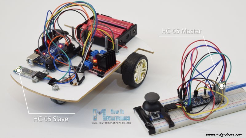
Neste tutorial vamos aprender a controlar sem fio o carro robô Arduino que fizemos no vídeo anterior. Mostrarei três métodos diferentes de controle sem fio, usando o módulo Bluetooth HC-05, o módulo transceptor NRF24L01 e o módulo sem fio de longo alcance HC-12, além de usar um Smartphone e um aplicativo Android personalizado. Você pode assistir ao vídeo a seguir ou ler o tutorial escrito abaixo para obter mais detalhes.
Já tenho tutoriais de como conectar e usar cada um desses módulos com a placa Arduino, então se precisar de mais detalhes pode sempre conferir. Os links para cada um deles podem ser encontrados abaixo no artigo.
Arduino Robot Car Control usando o módulo Bluetooth HC-05
Começaremos com a comunicação Bluetooth, e para isso precisamos de dois módulos Bluetooth HC-05 que precisam ser configurados como dispositivos mestre e escravo.
Podemos fazer isso facilmente usando comandos AT, e configurei o joystick como mestre e o carro robô do Arduino como escravo. Aqui está o esquema completo do circuito para este exemplo:
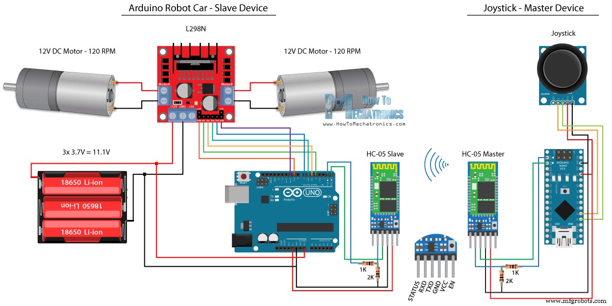
Você pode obter os componentes necessários para este exemplo nos links abaixo:
- Módulo Bluetooth HC-05 ………….…
- Módulo de joystick …………………………….
- 18650 baterias ……………………………..
- Carregador de bateria 18650…………………
- Motorista L298N ………………………………..
- Motor CC de alto torque de 12V …………
- Placa Arduino ………………………………
Código-fonte
Usaremos o mesmo código do tutorial anterior, onde controlamos o carro robô do Arduino diretamente pelo joystick, e faremos algumas modificações nele.
Código mestre HC-05:
/*
   Arduino Robot Car Wireless Control using the HC-05 Bluetooth

                == MASTER DEVICE - Joystick ==

   by Dejan Nedelkovski, www.HowToMechatronics.com
*/

int xAxis, yAxis;

void setup() {
  Serial.begin(38400); // Default communication rate of the Bluetooth module
}

void loop() {
  xAxis = analogRead(A0); // Read Joysticks X-axis
  yAxis = analogRead(A1); // Read Joysticks Y-axis

  // Send the values via the serial port to the slave HC-05 Bluetooth device
  Serial.write(xAxis/4); // Dividing by 4 for converting from 0 - 1023 to 0 - 256, (1 byte) range
  Serial.write(yAxis/4);
  delay(20);
}Code language: Arduino (arduino)
O código no dispositivo mestre, ou joystick, é bastante simples. Basta ler os valores X e Y do joystick, que na verdade regulam a velocidade dos motores, e enviá-los pela porta serial para o dispositivo Bluetooth escravo HC-05. Podemos notar aqui que os valores analógicos do joystick de 0 a 1023 são convertidos em valores de 0 a 255 mergulhando-os em 4.
Fazemos isso porque esse intervalo, de 0 a 255, pode ser enviado, pelo dispositivo Bluetooth, como 1 byte que é mais fácil de ser aceito do outro lado, ou no carro robô do Arduino.
Então aqui, se o serial recebeu os 2 bytes, os valores X e Y, usando a função Serial.read() vamos ler os dois.
// Code from the Arduino Robot Car

// Read the incoming data from the Joystick, or the master Bluetooth device
  while (Serial.available() >= 2) {
    x = Serial.read();
    delay(10);
    y = Serial.read();
  }Code language: Arduino (arduino)
Agora é só converter os valores de volta para o intervalo de 0 a 1023, adequado para o código de controle do motor abaixo, que já explicamos como funciona no vídeo anterior.
// Code from the Arduino Robot Car

// Convert back the 0 - 255 range to 0 - 1023, suitable for motor control code below
xAxis = x*4;
yAxis = y*4;Code language: Arduino (arduino)
Apenas uma observação rápida que ao fazer o upload do código, precisamos desconectar os pinos RX e TX da placa Arduino.
Código escravo HC-05 completo:
/*
   Arduino Robot Car Wireless Control using the HC-05 Bluetooth

             == SLAVE DEVICE - Arduino robot car ==

   by Dejan Nedelkovski, www.HowToMechatronics.com
*/

#define enA 9
#define in1 4
#define in2 5
#define enB 10
#define in3 6
#define in4 7

int xAxis, yAxis;
unsigned int  x = 0;
unsigned int  y = 0;

int motorSpeedA = 0;
int motorSpeedB = 0;

void setup() {
  pinMode(enA, OUTPUT);
  pinMode(enB, OUTPUT);
  pinMode(in1, OUTPUT);
  pinMode(in2, OUTPUT);
  pinMode(in3, OUTPUT);
  pinMode(in4, OUTPUT);

  Serial.begin(38400); // Default communication rate of the Bluetooth module
}

void loop() {
  // Default value - no movement when the Joystick stays in the center
  x = 510 / 4;
  y = 510 / 4;

  // Read the incoming data from the Joystick, or the master Bluetooth device
  while (Serial.available() >= 2) {
    x = Serial.read();
    delay(10);
    y = Serial.read();
  }
  delay(10);
  // Convert back the 0 - 255 range to 0 - 1023, suitable for motor control code below
  xAxis = x*4;
  yAxis = y*4;

  // Y-axis used for forward and backward control
  if (yAxis < 470) {
    // Set Motor A backward
    digitalWrite(in1, HIGH);
    digitalWrite(in2, LOW);
    // Set Motor B backward
    digitalWrite(in3, HIGH);
    digitalWrite(in4, LOW);
    // Convert the declining Y-axis readings for going backward from 470 to 0 into 0 to 255 value for the PWM signal for increasing the motor speed
    motorSpeedA = map(yAxis, 470, 0, 0, 255);
    motorSpeedB = map(yAxis, 470, 0, 0, 255);
  }
  else if (yAxis > 550) {
    // Set Motor A forward
    digitalWrite(in1, LOW);
    digitalWrite(in2, HIGH);
    // Set Motor B forward
    digitalWrite(in3, LOW);
    digitalWrite(in4, HIGH);
    // Convert the increasing Y-axis readings for going forward from 550 to 1023 into 0 to 255 value for the PWM signal for increasing the motor speed
    motorSpeedA = map(yAxis, 550, 1023, 0, 255);
    motorSpeedB = map(yAxis, 550, 1023, 0, 255);
  }
  // If joystick stays in middle the motors are not moving
  else {
    motorSpeedA = 0;
    motorSpeedB = 0;
  }

  // X-axis used for left and right control
  if (xAxis < 470) {
    // Convert the declining X-axis readings from 470 to 0 into increasing 0 to 255 value
    int xMapped = map(xAxis, 470, 0, 0, 255);
    // Move to left - decrease left motor speed, increase right motor speed
    motorSpeedA = motorSpeedA - xMapped;
    motorSpeedB = motorSpeedB + xMapped;
    // Confine the range from 0 to 255
    if (motorSpeedA < 0) {
      motorSpeedA = 0;
    }
    if (motorSpeedB > 255) {
      motorSpeedB = 255;
    }
  }
  if (xAxis > 550) {
    // Convert the increasing X-axis readings from 550 to 1023 into 0 to 255 value
    int xMapped = map(xAxis, 550, 1023, 0, 255);
    // Move right - decrease right motor speed, increase left motor speed
    motorSpeedA = motorSpeedA + xMapped;
    motorSpeedB = motorSpeedB - xMapped;
    // Confine the range from 0 to 255
    if (motorSpeedA > 255) {
      motorSpeedA = 255;
    }
    if (motorSpeedB < 0) {
      motorSpeedB = 0;
    }
  }
  // Prevent buzzing at low speeds (Adjust according to your motors. My motors couldn't start moving if PWM value was below value of 70)
  if (motorSpeedA < 70) {
    motorSpeedA = 0;
  }
  if (motorSpeedB < 70) {
    motorSpeedB = 0;
  }
  analogWrite(enA, motorSpeedA); // Send PWM signal to motor A
  analogWrite(enB, motorSpeedB); // Send PWM signal to motor B
}Code language: Arduino (arduino)
Arduino Robot Car Control usando um smartphone e um aplicativo Android personalizado
h2>Em seguida, vamos ver como podemos controlar nosso carro robô Arduino usando um aplicativo Android personalizado. O esquema do circuito do carro robô é exatamente o mesmo do exemplo anterior, com o modo Bluetooth HC-05 definido como dispositivo escravo.
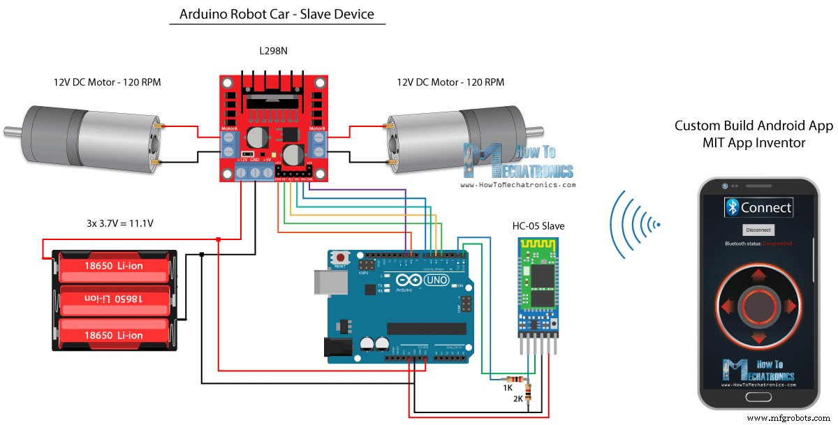
Por outro lado, usando o aplicativo on-line MIT App Inventor, construiremos nosso próprio aplicativo Android, e aqui está como ele fica.
Então, basicamente, o aplicativo simula um joystick, cuja aparência é feita de duas imagens, ou sprites de imagem.
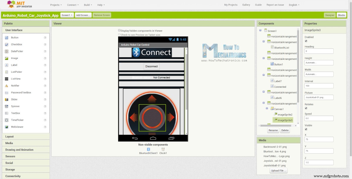
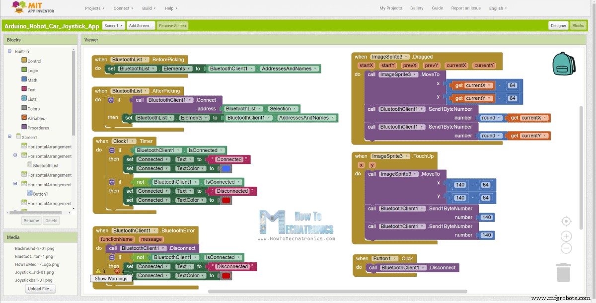
Se dermos uma olhada nos blocos deste aplicativo, podemos ver que quando o sprite do joystick é arrastado, a imagem da bola do joystick é movida para a localização atual do nosso dedo e, ao mesmo tempo, enviamos o X e o Y valores através do Bluetooth para o carro Arduino.
Esses valores são aceitos pelo Arduino da mesma forma que no exemplo anterior, utilizando a função Serial.read.
// Read the incoming data from the Smartphone Android App
  while (Serial.available() >= 2) {
    x = Serial.read();
    delay(10);
    y = Serial.read();
  }Code language: Arduino (arduino)
O que precisamos fazer adicionalmente aqui é converter os valores X e Y recebidos do smartphone no intervalo de 0 a 1023, adequado para o código de controle do motor abaixo. Esses valores dependem do tamanho da tela, e os valores X e Y que eu estava obtendo do meu aplicativo eram de 60 a 220, que usando a função map() eu os converti facilmente.
// Makes sure we receive corrent values
  if (x > 60 & x < 220) {
    xAxis = map(x, 220, 60, 1023, 0); // Convert the smartphone X and Y values to 0 - 1023 range, suitable motor for the motor control code below
  }
  if (y > 60 & y < 220) {
    yAxis = map(y, 220, 60, 0, 1023);
  }Code language: Arduino (arduino)
Nos blocos do aplicativo, também podemos ver que quando o sprite da imagem é retocado a bola do joystick volta para o centro da tela e os valores apropriados são enviados ao carro para parar de se mover. Você pode encontrar e baixar este aplicativo no artigo do site, bem como as duas imagens do joystick para que você possa criar o seu próprio ou modificar este aplicativo.
Você pode baixar o aplicativo Android abaixo, assim como as duas imagens do joystick:

Arduino_Robot_Car_Joystick_App.apk
1 arquivo(s) Download de 1,62 MB Arduino_Robot_Car_Joystick_App_aia_file
1 arquivo(s) Download de 171,20 KB Imagens de aplicativos de joystick
1 arquivo(s) Download de 44,36 KBCódigo Arduino completo:
/*
   Arduino Robot Car Wireless Control using the HC-05 Bluetooth and custom-build Android app

             == SLAVE DEVICE - Arduino robot car ==

   by Dejan Nedelkovski, www.HowToMechatronics.com
*/

#define enA 9
#define in1 4
#define in2 5
#define enB 10
#define in3 6
#define in4 7

int xAxis, yAxis;
int  x = 0;
int  y = 0;

int motorSpeedA = 0;
int motorSpeedB = 0;

void setup() {
  pinMode(enA, OUTPUT);
  pinMode(enB, OUTPUT);
  pinMode(in1, OUTPUT);
  pinMode(in2, OUTPUT);
  pinMode(in3, OUTPUT);
  pinMode(in4, OUTPUT);

  Serial.begin(38400); // Default communication rate of the Bluetooth module
}

void loop() {
  // Default value - no movement when the Joystick stays in the center
  xAxis = 510;
  yAxis = 510;

  // Read the incoming data from the Smartphone Android App
  while (Serial.available() >= 2) {
    x = Serial.read();
    delay(10);
    y = Serial.read();
  }
  delay(10);

  // Makes sure we receive corrent values
  if (x > 60 & x < 220) {
    xAxis = map(x, 220, 60, 1023, 0); // Convert the smartphone X and Y values to 0 - 1023 range, suitable motor for the motor control code below
  }
  if (y > 60 & y < 220) {
    yAxis = map(y, 220, 60, 0, 1023);
  }

  // Y-axis used for forward and backward control
  if (yAxis < 470) {
    // Set Motor A backward
    digitalWrite(in1, HIGH);
    digitalWrite(in2, LOW);
    // Set Motor B backward
    digitalWrite(in3, HIGH);
    digitalWrite(in4, LOW);
    // Convert the declining Y-axis readings for going backward from 470 to 0 into 0 to 255 value for the PWM signal for increasing the motor speed
    motorSpeedA = map(yAxis, 470, 0, 0, 255);
    motorSpeedB = map(yAxis, 470, 0, 0, 255);
  }
  else if (yAxis > 550) {
    // Set Motor A forward
    digitalWrite(in1, LOW);
    digitalWrite(in2, HIGH);
    // Set Motor B forward
    digitalWrite(in3, LOW);
    digitalWrite(in4, HIGH);
    // Convert the increasing Y-axis readings for going forward from 550 to 1023 into 0 to 255 value for the PWM signal for increasing the motor speed
    motorSpeedA = map(yAxis, 550, 1023, 0, 255);
    motorSpeedB = map(yAxis, 550, 1023, 0, 255);
  }
  // If joystick stays in middle the motors are not moving
  else {
    motorSpeedA = 0;
    motorSpeedB = 0;
  }

  // X-axis used for left and right control
  if (xAxis < 470) {
    // Convert the declining X-axis readings from 470 to 0 into increasing 0 to 255 value
    int xMapped = map(xAxis, 470, 0, 0, 255);
    // Move to left - decrease left motor speed, increase right motor speed
    motorSpeedA = motorSpeedA - xMapped;
    motorSpeedB = motorSpeedB + xMapped;
    // Confine the range from 0 to 255
    if (motorSpeedA < 0) {
      motorSpeedA = 0;
    }
    if (motorSpeedB > 255) {
      motorSpeedB = 255;
    }
  }
  if (xAxis > 550) {
    // Convert the increasing X-axis readings from 550 to 1023 into 0 to 255 value
    int xMapped = map(xAxis, 550, 1023, 0, 255);
    // Move right - decrease right motor speed, increase left motor speed
    motorSpeedA = motorSpeedA + xMapped;
    motorSpeedB = motorSpeedB - xMapped;
    // Confine the range from 0 to 255
    if (motorSpeedA > 255) {
      motorSpeedA = 255;
    }
    if (motorSpeedB < 0) {
      motorSpeedB = 0;
    }
  }
  // Prevent buzzing at low speeds (Adjust according to your motors. My motors couldn't start moving if PWM value was below value of 70)
  if (motorSpeedA < 70) {
    motorSpeedA = 0;
  }
  if (motorSpeedB < 70) {
    motorSpeedB = 0;
  }
  analogWrite(enA, motorSpeedA); // Send PWM signal to motor A
  analogWrite(enB, motorSpeedB); // Send PWM signal to motor B
}Code language: Arduino (arduino)
Controle sem fio do carro robô Arduino usando o módulo transceptor NRF24L01
Agora podemos passar para o próximo método, controle sem fio do carro robô Arduino usando os módulos transceptores NRF24L01.
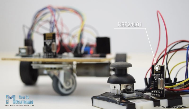
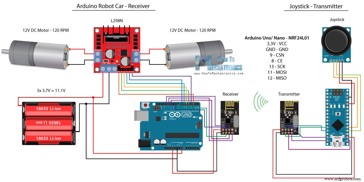
Aqui está o esquema do circuito. Podemos notar que esses módulos usam a comunicação SPI, então comparado ao exemplo anterior, eu tive que mover os pinos Enable A e Enable B do driver L298N para os pinos número 2 e 3 da placa Arduino. Você pode obter o NRF24L01 módulo no seguinte link da Amazon.
Código-fonte
Para este exemplo, precisamos instalar a biblioteca RF24. De forma semelhante ao exemplo anterior, após definir alguns pinos e configurar o módulo como transmissor, lemos os valores X e Y do joystick e os enviamos para o outro módulo NRF24L01 no carro do robô Arduino.
Primeiro podemos notar que as leituras analógicas são Strings, que usando a função string.toCharArray() são colocadas em um array de caracteres. Em seguida, usando a função radio.write(), enviamos os dados da matriz de caracteres para o outro módulo.
Código do transmissor:
/*
   Arduino Robot Car Wireless Control using the NRF24L01 Transceiver module

             == Transmitter - Joystick ==

   by Dejan Nedelkovski, www.HowToMechatronics.com

   Library: TMRh20/RF24, https://github.com/tmrh20/RF24/
*/

#include <SPI.h>
#include <nRF24L01.h>
#include <RF24.h>

RF24 radio(8, 9); // CE, CSN
const byte address[6] = "00001";

char xyData[32] = "";
String xAxis, yAxis;

void setup() {
  Serial.begin(9600);
  radio.begin();
  radio.openWritingPipe(address);
  radio.setPALevel(RF24_PA_MIN);
  radio.stopListening();
}

void loop() {

  xAxis = analogRead(A0); // Read Joysticks X-axis
  yAxis = analogRead(A1); // Read Joysticks Y-axis
  // X value
  xAxis.toCharArray(xyData, 5); // Put the String (X Value) into a character array
  radio.write(&xyData, sizeof(xyData)); // Send the array data (X value) to the other NRF24L01 modile
  // Y value
  yAxis.toCharArray(xyData, 5);
  radio.write(&xyData, sizeof(xyData));
  delay(20);
}Code language: Arduino (arduino)
Por outro lado. no carro robô do Arduino, após definir o módulo como receptor, aceitamos os dados usando a função radio.read(). Em seguida, usando a função atoi(), convertemos os dados recebidos, ou os valores X e Y do joystick, em valores inteiros, que são adequados para o código de controle do motor abaixo.
// Code from the Arduino Robot Car - NRF24L01 example

if (radio.available()) {   // If the NRF240L01 module received data
    radio.read(&receivedData, sizeof(receivedData)); // Read the data and put it into character array
    xAxis = atoi(&receivedData[0]); // Convert the data from the character array (received X value) into integer
    delay(10);
    radio.read(&receivedData, sizeof(receivedData));
    yAxis = atoi(&receivedData[0]);
    delay(10);
  }Code language: Arduino (arduino)
É simples assim, mas é claro que como eu já disse, se você precisar de mais detalhes sobre como conectar e configurar os módulos, você sempre pode verificar meu tutorial específico para isso.
Código do receptor:
/*
   Arduino Robot Car Wireless Control using the NRF24L01 Transceiver module

             == Receiver - Arduino robot car ==

   by Dejan Nedelkovski, www.HowToMechatronics.com

   Library: TMRh20/RF24, https://github.com/tmrh20/RF24/
*/
#include <SPI.h>
#include <nRF24L01.h>
#include <RF24.h>

#define enA 2   // Note: Pin 9 in previous video ( pin 10 is used for the SPI communication of the NRF24L01)
#define in1 4
#define in2 5
#define enB 3   // Note:  Pin 10 in previous video
#define in3 6
#define in4 7

RF24 radio(8, 9); // CE, CSN
const byte address[6] = "00001";

char receivedData[32] = "";
int  xAxis, yAxis;

int motorSpeedA = 0;
int motorSpeedB = 0;

void setup() {
  pinMode(enA, OUTPUT);
  pinMode(enB, OUTPUT);
  pinMode(in1, OUTPUT);
  pinMode(in2, OUTPUT);
  pinMode(in3, OUTPUT);
  pinMode(in4, OUTPUT);
  Serial.begin(9600);
  radio.begin();
  radio.openReadingPipe(0, address);
  radio.setPALevel(RF24_PA_MIN);
  radio.startListening();
}

void loop() {

  if (radio.available()) {   // If the NRF240L01 module received data
    radio.read(&receivedData, sizeof(receivedData)); // Read the data and put it into character array
    xAxis = atoi(&receivedData[0]); // Convert the data from the character array (received X value) into integer
    delay(10);
    radio.read(&receivedData, sizeof(receivedData));
    yAxis = atoi(&receivedData[0]);
    delay(10);
  }

  // Y-axis used for forward and backward control
  if (yAxis < 470) {
    // Set Motor A backward
    digitalWrite(in1, HIGH);
    digitalWrite(in2, LOW);
    // Set Motor B backward
    digitalWrite(in3, HIGH);
    digitalWrite(in4, LOW);
    // Convert the declining Y-axis readings for going backward from 470 to 0 into 0 to 255 value for the PWM signal for increasing the motor speed
    motorSpeedA = map(yAxis, 470, 0, 0, 255);
    motorSpeedB = map(yAxis, 470, 0, 0, 255);
  }
  else if (yAxis > 550) {
    // Set Motor A forward
    digitalWrite(in1, LOW);
    digitalWrite(in2, HIGH);
    // Set Motor B forward
    digitalWrite(in3, LOW);
    digitalWrite(in4, HIGH);
    // Convert the increasing Y-axis readings for going forward from 550 to 1023 into 0 to 255 value for the PWM signal for increasing the motor speed
    motorSpeedA = map(yAxis, 550, 1023, 0, 255);
    motorSpeedB = map(yAxis, 550, 1023, 0, 255);
  }
  // If joystick stays in middle the motors are not moving
  else {
    motorSpeedA = 0;
    motorSpeedB = 0;
  }

  // X-axis used for left and right control
  if (xAxis < 470) {
    // Convert the declining X-axis readings from 470 to 0 into increasing 0 to 255 value
    int xMapped = map(xAxis, 470, 0, 0, 255);
    // Move to left - decrease left motor speed, increase right motor speed
    motorSpeedA = motorSpeedA - xMapped;
    motorSpeedB = motorSpeedB + xMapped;
    // Confine the range from 0 to 255
    if (motorSpeedA < 0) {
      motorSpeedA = 0;
    }
    if (motorSpeedB > 255) {
      motorSpeedB = 255;
    }
  }
  if (xAxis > 550) {
    // Convert the increasing X-axis readings from 550 to 1023 into 0 to 255 value
    int xMapped = map(xAxis, 550, 1023, 0, 255);
    // Move right - decrease right motor speed, increase left motor speed
    motorSpeedA = motorSpeedA + xMapped;
    motorSpeedB = motorSpeedB - xMapped;
    // Confine the range from 0 to 255
    if (motorSpeedA > 255) {
      motorSpeedA = 255;
    }
    if (motorSpeedB < 0) {
      motorSpeedB = 0;
    }
  }
  // Prevent buzzing at low speeds (Adjust according to your motors. My motors couldn't start moving if PWM value was below value of 70)
  if (motorSpeedA < 70) {
    motorSpeedA = 0;
  }
  if (motorSpeedB < 70) {
    motorSpeedB = 0;
  }
  analogWrite(enA, motorSpeedA); // Send PWM signal to motor A
  analogWrite(enB, motorSpeedB); // Send PWM signal to motor B
}Code language: Arduino (arduino)
Controle sem fio do carro robô Arduino usando o transceptor de longo alcance HC-12
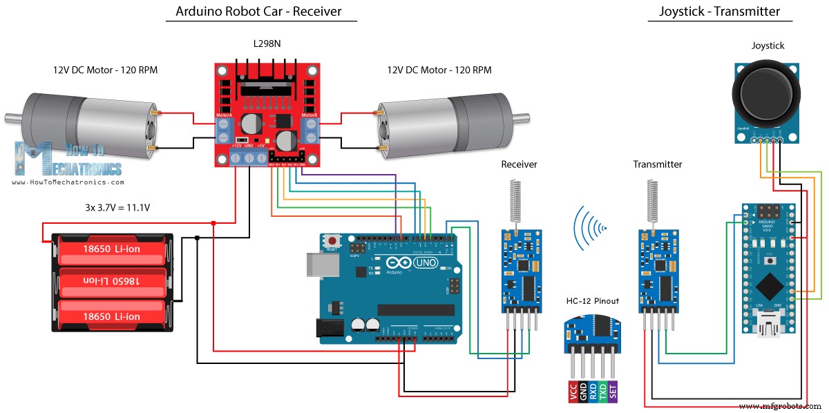
Para o último método de controle sem fio do carro robô Arduino, usaremos os módulos transceptores de longo alcance HC-12. Esses módulos podem se comunicar entre si com distâncias de até 1,8 km.
O esquema do circuito para este exemplo é quase o mesmo dos módulos Bluetooth HC-05, pois eles estão usando o mesmo método de comunicação com o Arduino, via porta serial.
Você pode obter o módulo HC-12 Transceiver no seguinte link da Amazon.
Código-fonte
O código do Joystick é exatamente o mesmo da comunicação Bluetooth. Nós apenas lemos os valores analógicos do joystick e os enviamos para o outro módulo usando a função Serial.write().
Código do transmissor:
/*
   Arduino Robot Car Wireless Control using the HC-12 long range wireless module

                == Transmitter - Joystick ==

   by Dejan Nedelkovski, www.HowToMechatronics.com
*/

int xAxis, yAxis;

void setup() {
  Serial.begin(9600); // Default communication rate of the Bluetooth module
}

void loop() {
  xAxis = analogRead(A0); // Read Joysticks X-axis
  yAxis = analogRead(A1); // Read Joysticks Y-axis

  // Send the values via the serial port to the slave HC-05 Bluetooth device
  Serial.write(xAxis/4); // Dividing by 4 for converting from 0 - 1023 to 0 - 256, (1 byte) range
  Serial.write(yAxis/4);
  delay(20);
}Code language: Arduino (arduino)
Por outro lado, com o loop while() esperamos até que os dados cheguem, então lemos usando a função Serial.read() e convertemos de volta para o intervalo de 0 a 1023, adequado para o código de controle do motor abaixo.
Código do receptor:
/*
   Arduino Robot Car Wireless Control using the HC-12 long range wireless module

             == Receiver - Arduino robot car ==

   by Dejan Nedelkovski, www.HowToMechatronics.com
*/

#define enA 9
#define in1 4
#define in2 5
#define enB 10
#define in3 6
#define in4 7

int xAxis, yAxis;
int  x = 0;
int  y = 0;

int motorSpeedA = 0;
int motorSpeedB = 0;

void setup() {
  pinMode(enA, OUTPUT);
  pinMode(enB, OUTPUT);
  pinMode(in1, OUTPUT);
  pinMode(in2, OUTPUT);
  pinMode(in3, OUTPUT);
  pinMode(in4, OUTPUT);

  Serial.begin(9600); // Default communication rate of the Bluetooth module
}

void loop() {
  // Default value - no movement when the Joystick stays in the center
  xAxis = 510;
  yAxis = 510;

  // Read the incoming data from the
  while (Serial.available() == 0) {}
  x = Serial.read();
  delay(10);
  y = Serial.read();
  delay(10);

  // Convert back the 0 - 255 range to 0 - 1023, suitable for motor control code below
  xAxis = x * 4;
  yAxis = y * 4;

  // Y-axis used for forward and backward control
  if (yAxis < 470) {
    // Set Motor A backward
    digitalWrite(in1, HIGH);
    digitalWrite(in2, LOW);
    // Set Motor B backward
    digitalWrite(in3, HIGH);
    digitalWrite(in4, LOW);
    // Convert the declining Y-axis readings for going backward from 470 to 0 into 0 to 255 value for the PWM signal for increasing the motor speed
    motorSpeedA = map(yAxis, 470, 0, 0, 255);
    motorSpeedB = map(yAxis, 470, 0, 0, 255);
  }
  else if (yAxis > 550) {
    // Set Motor A forward
    digitalWrite(in1, LOW);
    digitalWrite(in2, HIGH);
    // Set Motor B forward
    digitalWrite(in3, LOW);
    digitalWrite(in4, HIGH);
    // Convert the increasing Y-axis readings for going forward from 550 to 1023 into 0 to 255 value for the PWM signal for increasing the motor speed
    motorSpeedA = map(yAxis, 550, 1023, 0, 255);
    motorSpeedB = map(yAxis, 550, 1023, 0, 255);
  }
  // If joystick stays in middle the motors are not moving
  else {
    motorSpeedA = 0;
    motorSpeedB = 0;
  }

  // X-axis used for left and right control
  if (xAxis < 470) {
    // Convert the declining X-axis readings from 470 to 0 into increasing 0 to 255 value
    int xMapped = map(xAxis, 470, 0, 0, 255);
    // Move to left - decrease left motor speed, increase right motor speed
    motorSpeedA = motorSpeedA - xMapped;
    motorSpeedB = motorSpeedB + xMapped;
    // Confine the range from 0 to 255
    if (motorSpeedA < 0) {
      motorSpeedA = 0;
    }
    if (motorSpeedB > 255) {
      motorSpeedB = 255;
    }
  }
  if (xAxis > 550) {
    // Convert the increasing X-axis readings from 550 to 1023 into 0 to 255 value
    int xMapped = map(xAxis, 550, 1023, 0, 255);
    // Move right - decrease right motor speed, increase left motor speed
    motorSpeedA = motorSpeedA + xMapped;
    motorSpeedB = motorSpeedB - xMapped;
    // Confine the range from 0 to 255
    if (motorSpeedA > 255) {
      motorSpeedA = 255;
    }
    if (motorSpeedB < 0) {
      motorSpeedB = 0;
    }
  }
  // Prevent buzzing at low speeds (Adjust according to your motors. My motors couldn't start moving if PWM value was below value of 70)
  if (motorSpeedA < 70) {
    motorSpeedA = 0;
  }
  if (motorSpeedB < 70) {
    motorSpeedB = 0;
  }
  analogWrite(enA, motorSpeedA); // Send PWM signal to motor A
  analogWrite(enB, motorSpeedB); // Send PWM signal to motor B
}Code language: Arduino (arduino)
Então, isso é praticamente tudo para este tutorial. Sinta-se à vontade para fazer qualquer pergunta na seção de comentários abaixo.
Como controlar LEDs endereçáveis individualmente WS2812B usando Arduino
Motorista L298N – Interface Arduino, Como Funciona, Códigos, Esquemas
Processo de manufatura
- Robô Raspberry Pi controlado por Bluetooth
- Controle remoto universal usando Arduino, 1Sheeld e Android
- Faça você mesmo voltímetro usando Arduino e Smartphone
- Arduino com Bluetooth para controlar um LED!
- Controle o Arduino Rover usando Firmata e o controlador do Xbox One
- Contador de carros usando Arduino + Processing + PHP
- Controle total de sua TV usando Alexa e Arduino IoT Cloud
- Rádio FM usando Arduino e RDA8057M
- BLUE_P:Wireless Arduino Programming Shield
- Controle do carro com Arduino Uno e Bluetooth