


Módulo de comunicação sem fio de longo alcance Arduino e HC-12
Neste tutorial do Arduino vamos aprender a usar o módulo de comunicação serial sem fio HC-12 que é capaz de fazer uma comunicação sem fio de longo alcance entre várias placas Arduino, com distâncias de até 1,8km. Você pode assistir ao vídeo a seguir ou ler o tutorial escrito abaixo para obter mais detalhes.
Visão geral
Para este tutorial fiz dois exemplos básicos explicando como conectar o módulo HC-12 e fazer uma comunicação básica entre dois Arduinos e um exemplo adicional onde usando um sensor de acelerômetro no primeiro Arduino eu controlo sem fio a posição do stepper no segundo Arduíno.
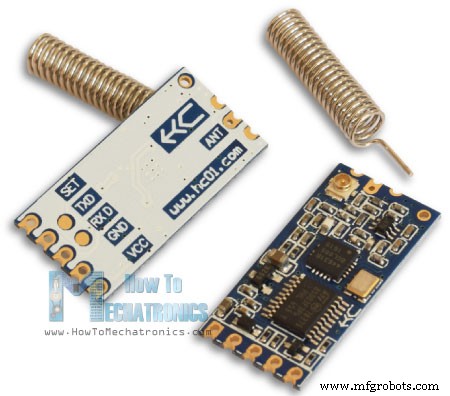
Módulo de comunicação sem fio HC-12
Primeiro vamos dar uma olhada no módulo de comunicação da porta serial sem fio HC-12. Aqui estão algumas especificações:
- Sua banda de frequência de trabalho sem fio é de 433,4 MHz a 473,0 MHz
- Tem um total de 100 canais com um passo de 400 KHz entre cada canal
- A potência de transmissão é de -1dBm (0,79mW) a 20dBm (100mW)
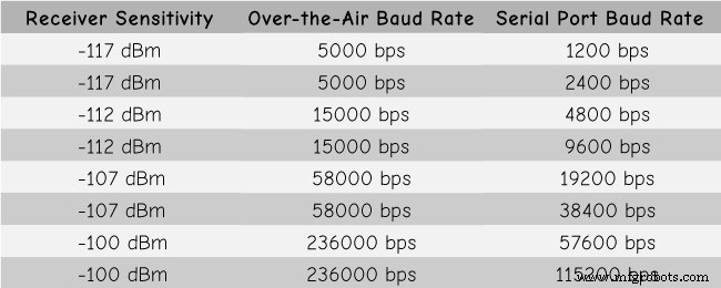
- A sensibilidade de recepção é de -117dBm (0,019pW) a -100dBm (10pW).
Esses valores, na verdade, dependem da taxa de transmissão serial e over-the-air selecionada, conforme mostrado na tabela.
O módulo HC-12 possui um microcontrolador que na verdade não precisa ser programado pelo usuário. Para configurar o módulo, basta usar comandos AT, que podem ser enviados de um Arduino, um PC ou qualquer outro microcontrolador usando a porta serial. Para entrar no modo de comando AT, basta definir o pino “Set” do módulo para um nível lógico baixo.
Arduino e HC-12
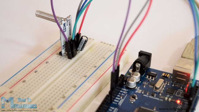
Agora vamos conectar o módulo HC-12 ao Arduino e fazer o primeiro exemplo. Aqui está o esquema do circuito. A tensão de operação do módulo é de 3,2 V a 5,5 V e para um trabalho mais estável é recomendado o uso de um capacitor de desacoplamento e uma fonte de alimentação externa. No entanto, usei o USB do PC como energia para todos os três exemplos deste tutorial e não tive nenhum problema com isso.
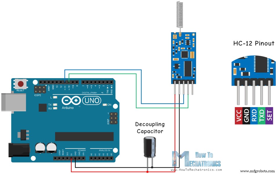
Liguei o primeiro módulo a um Arduino UNO e o segundo módulo a um Arduino MEGA, mas claro, você pode usar qualquer placa que quiser.
Você pode obter os componentes necessários para este tutorial do Arduino nos links abaixo:
- Módulo de comunicação sem fio HC-12 ………..
- Placa Arduino ………………………………………………
- Breadboard e jump wires ………………………
Exemplo 01 – Código Arduino
Aqui está o código do Arduino para o primeiro exemplo, uma comunicação básica entre os dois módulos usando o Serial Monitor.
/*    Arduino Long Range Wireless Communication using HC-12
                      Example 01
   by Dejan Nedelkovski, www.HowToMechatronics.com
*/

#include <SoftwareSerial.h>

SoftwareSerial HC12(10, 11); // HC-12 TX Pin, HC-12 RX Pin

void setup() {
  Serial.begin(9600);             // Serial port to computer
  HC12.begin(9600);               // Serial port to HC12

}

void loop() {
  while (HC12.available()) {        // If HC-12 has data
    Serial.write(HC12.read());      // Send the data to Serial monitor
  }
  while (Serial.available()) {      // If Serial monitor has data
    HC12.write(Serial.read());      // Send that data to HC-12
  }
}Code language: Arduino (arduino)
O mesmo código é usado para ambos os Arduinos. Podemos conectar os dois Arduinos em dois computadores separados, mas também podemos usar um único computador.
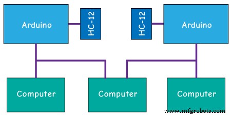
Nesse caso, uma vez que conectamos o primeiro Arduino ao computador, precisamos selecionar o modelo e a porta COM e fazer o upload do código para o Arduino. Em seguida, conectamos o segundo Arduino e temos que iniciar o Arduino IDE novamente para poder selecionar a outra porta COM à qual nosso segundo Arduino está conectado e, em seguida, fazer o upload do mesmo código.
Assim, uma vez que temos os dois IDEs do Arduino em execução, podemos iniciar os monitores seriais e testar se a comunicação funciona corretamente. Qualquer coisa que digitarmos no monitor serial será enviada de um para o outro Arduino.
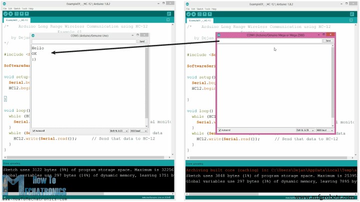
Como o código funciona: Assim que digitarmos algo no monitor serial e clicarmos no botão Send, no primeiro Arduino, o loop while com a função Serial.available() se tornará verdadeiro e usando a função HC12.write() enviaremos os dados do monitor serial para o módulo HC-12. Este módulo irá transferir os dados sem fio para o segundo módulo HC-12, então no segundo Arduino o loop while com a função HC12.available() se tornará verdadeiro e usando a função Serial.write() os dados serão enviados para o monitor serial.
Podemos usar o mesmo código para enviar comandos AT e configurar os parâmetros do módulo. Tudo o que precisamos fazer é conectar o pino “Set” do módulo ao Ground ou qualquer pino digital do Arduino e definir o pino para nível lógico baixo.
Para testar se entramos com sucesso no modo, no monitor serial podemos digitar “AT” e devemos receber uma mensagem de resposta “OK”. Há um total de 12 comandos AT, e eles são usados para alterar vários parâmetros, como a taxa de transmissão, o canal, a potência de transmissão etc. Por exemplo, se digitarmos "AT+B38400", a taxa de transmissão do módulo será definida como 38400.
Comandos AT:
1. AT – Comando de teste.
Exemplo:Envie “AT” para o módulo, e o módulo retorna “OK”.
2. AT+Bxxxx – Alterar a taxa de transmissão da porta serial.
Taxas de transmissão disponíveis:1200 bps, 2400 bps, 4800 bps, 9600 bps, 19200 bps, 38400 bps, 57600 bps e 115200 bps. Padrão:9600 bps.
Exemplo:Envie “AT+B38400” para o módulo, e o módulo retorna “OK+B19200”.
3. AT+Cxxxx - Mude o canal de comunicação sem fio, de 001 para 100.
Padrão:Canal 001, com frequência de trabalho de 433,4MHz. Cada canal seguinte é 400KHz mais alto.
Exemplo: Se quisermos definir o módulo para o canal 006, precisamos enviar o comando “AT+C006” para o módulo e o módulo retornará “OK+C006”. A nova frequência de trabalho será de 435,4 MHz.
Exemplo 02
Agora vamos mover o segundo exemplo. Aqui usaremos dois botões para selecionar diferentes canais de comunicação e veremos um método diferente de armazenar os dados recebidos.
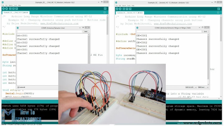
Nota:Os pinos “Set” de ambos os módulos HC-12 são conectados aos pinos número 6 dos dois Arduinos e os dois botões, no primeiro Arduino, aos pinos 4 e 3.
Primeiro código Arduino:
/*    Arduino Long Range Wireless Communication using HC-12
    Example 02 - Changing channels using push buttons - Buttons side
   by Dejan Nedelkovski, www.HowToMechatronics.com
*/

#include <SoftwareSerial.h>

#define setPin 6
#define button1 4
#define button2 3

SoftwareSerial HC12(10, 11);         // HC-12 TX Pin, HC-12 RX Pin

byte incomingByte;
String readBuffer = "";

int button1State = 0;
int button1Pressed = 0;
int button2State = 0;
int button2Pressed = 0;

void setup() {
  Serial.begin(9600);                   // Open serial port to computer
  HC12.begin(9600);                     // Open serial port to HC12
  pinMode(setPin, OUTPUT);
  pinMode(button1, INPUT);
  pinMode(button2, INPUT);
  digitalWrite(setPin, HIGH);           // HC-12 normal, transparent mode
}

void loop() {
  // ==== Storing the incoming data into a String variable
  while (HC12.available()) {             // If HC-12 has data
    incomingByte = HC12.read();          // Store each icoming byte from HC-12
    readBuffer += char(incomingByte);    // Add each byte to ReadBuffer string variable
  }
  delay(100);
  // ==== Sending data from one HC-12 to another via the Serial Monitor
  while (Serial.available()) {
    HC12.write(Serial.read());
  }

  // ==== If button 1 is pressed, set the channel 01
  button1State = digitalRead(button1);
  if (button1State == HIGH & button1Pressed == LOW) {
    button1Pressed = HIGH;
    delay(20);
  }
  if (button1Pressed == HIGH) {
    HC12.print("AT+C001");               // Send the AT Command to the other module
    delay(100);
    //Set AT Command Mode
    digitalWrite(setPin, LOW);           // Set HC-12 into AT Command mode
    delay(100);                          // Wait for the HC-12 to enter AT Command mode
    HC12.print("AT+C001");               // Send AT Command to HC-12
    delay(200);
    while (HC12.available()) {           // If HC-12 has data (the AT Command response)
      Serial.write(HC12.read());         // Send the data to Serial monitor
    }
    Serial.println("Channel successfully changed");
    digitalWrite(setPin, HIGH);          // Exit AT Command mode
    button1Pressed = LOW;
  }

  // ====  If button 2 is pressed, set the channel 02
  button2State = digitalRead(button2);
  if (button2State == HIGH & button2Pressed == LOW) {
    button2Pressed = HIGH;
    delay(100);
  }
  if (button2Pressed == HIGH) {
    HC12.print("AT+C002"); // Send the AT Command to the other module
    delay(100);
    //Set AT Command Mode
    digitalWrite(setPin, LOW);           // Set HC-12 into AT Command mode
    delay(100);                          // Wait for the HC-12 to enter AT Command mode
    HC12.print("AT+C002");               // Send AT Command to HC-12
    delay(200);
    while (HC12.available()) {           // If HC-12 has data (the AT Command response)
      Serial.write(HC12.read());         // Send the data to Serial monitor
    }
    Serial.println("Channel successfully changed");
    digitalWrite(setPin, HIGH);
    button2Pressed = LOW;
  }
  checkATCommand();
  readBuffer = "";                       // Clear readBuffer
}
// ==== Custom function - Check whether we have received an AT Command via the Serial Monitor
void checkATCommand () {
  if (readBuffer.startsWith("AT")) {     // Check whether the String starts with "AT"
    digitalWrite(setPin, LOW);           // Set HC-12 into AT Command mode
    delay(200);                          // Wait for the HC-12 to enter AT Command mode
    HC12.print(readBuffer);              // Send AT Command to HC-12
    delay(200);
    while (HC12.available()) {           // If HC-12 has data (the AT Command response)
      Serial.write(HC12.read());         // Send the data to Serial monitor
    }
    digitalWrite(setPin, HIGH);          // Exit AT Command mode
  }
}Code language: Arduino (arduino)
Segundo código Arduino:
/*    Arduino Long Range Wireless Communication using HC-12
        Example 02 - Changing channels using push buttons
   by Dejan Nedelkovski, www.HowToMechatronics.com
*/

#include <SoftwareSerial.h>

#define setPin 6

SoftwareSerial HC12(10, 11); // HC-12 TX Pin, HC-12 RX Pin

byte incomingByte;
String readBuffer = "";

void setup() {
  Serial.begin(9600);             // Open serial port to computer
  HC12.begin(9600);               // Open serial port to HC12
  pinMode(setPin, OUTPUT);
  digitalWrite(setPin, HIGH);     // HC-12 normal mode
}

void loop() {
  // ==== Storing the incoming data into a String variable
  while (HC12.available()) {             // If HC-12 has data
    incomingByte = HC12.read();          // Store each icoming byte from HC-12
    readBuffer += char(incomingByte);    // Add each byte to ReadBuffer string variable
  }
  delay(100);
  // ==== Sending data from one HC-12 to another via the Serial Monitor
  while (Serial.available()) {
    HC12.write(Serial.read());
  }
  // === If button 1 is pressed, set channel 01
  if (readBuffer == "AT+C001") {
    digitalWrite(setPin, LOW);           // Set HC-12 into AT Command mode
    delay(100);                          // Wait for the HC-12 to enter AT Command mode
    HC12.print(readBuffer);              // Send AT Command to HC-12 ("AT+C001")
    delay(200);
    while (HC12.available()) {           // If HC-12 has data (the AT Command response)
      Serial.write(HC12.read());         // Send the data to Serial monitor
    }
    Serial.println("Channel successfully changed");
    digitalWrite(setPin, HIGH);          // Exit AT Command mode
    readBuffer = "";
  }
  // === If button 2 is pressed, set channel 02
  if (readBuffer == "AT+C002") {
    digitalWrite(setPin, LOW);           // Set HC-12 into AT Command mode
    delay(100);                          // Wait for the HC-12 to enter AT Command mode
    HC12.print(readBuffer);              // Send AT Command to HC-12
    delay(200);
    while (HC12.available()) {           // If HC-12 has data (the AT Command response)
      Serial.write(HC12.read());         // Send the data to Serial monitor
    }
    Serial.println("Channel successfully changed");
    digitalWrite(setPin, HIGH);          // Exit AT Command mode

    readBuffer = "";
  }
  checkATCommand();
  readBuffer = "";                       // Clear readBuffer
}
// ==== Custom function - Check whether we have received an AT Command via the Serial Monitor
void checkATCommand () {
  if (readBuffer.startsWith("AT")) {     // Check whether the String starts with "AT"
    digitalWrite(setPin, LOW);           // Set HC-12 into AT Command mode
    delay(100);                          // Wait for the HC-12 to enter AT Command mode
    HC12.print(readBuffer);              // Send AT Command to HC-12
    delay(200);
    while (HC12.available()) {           // If HC-12 has data (the AT Command response)
      Serial.write(HC12.read());         // Send the data to Serial monitor
    }
    digitalWrite(setPin, HIGH);          // Exit AT Command mode
  }
}Code language: Arduino (arduino)
Descrição dos códigos:
Então, primeiro precisamos definir os pinos e definir o pino “Set” para alto nível lógico para que o módulo funcione no modo normal e transparente. Com o primeiro loop while, armazenamos os dados de entrada em uma variável String, para que possamos lidar melhor com isso.
// ==== Storing the incoming data into a String variable
while (HC12.available()) { // If HC-12 has data
incomingByte = HC12.read(); // Store each icoming byte from HC-12
readBuffer += char(incomingByte); // Add each byte to ReadBuffer string variable
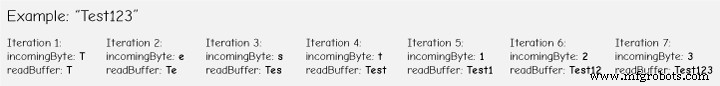
}Code language: Arduino (arduino)Os dados de entrada sempre vêm um byte de cada vez, então, por exemplo, se enviarmos a string “Test123” do segundo Arduino, esse loop while fará 7 iterações. A cada iteração, usando a função HC12.read(), leremos cada byte ou caractere de entrada e o adicionaremos à variável String chamada “readBuffer”.
Em seguida, vamos ver como podemos alterar o canal de comunicação usando o primeiro botão. Portanto, se pressionarmos o primeiro botão, usando a função HC12.print(), enviaremos a string “AT+C001” para o módulo HC-12 ou para o segundo Arduino.
if (button1Pressed == HIGH) {
    HC12.print("AT+C001");               // Send the AT Command to the other module
    delay(100);
    //Set AT Command Mode
    digitalWrite(setPin, LOW);           // Set HC-12 into AT Command mode
    delay(100);                          // Wait for the HC-12 to enter AT Command mode
    HC12.print("AT+C001");               // Send AT Command to HC-12
    delay(200);
    while (HC12.available()) {           // If HC-12 has data (the AT Command response)
      Serial.write(HC12.read());         // Send the data to Serial monitor
    }
    Serial.println("Channel successfully changed");
    digitalWrite(setPin, HIGH);          // Exit AT Command mode
    button1Pressed = LOW;
  }Code language: Arduino (arduino)
Quando esta string for recebida no segundo Arduino, vamos definir o módulo HC-12 no modo de comando AT e, em seguida, escrever a mesma string “AT+C001” nele, que definirá o módulo para o canal de comunicação número um.
// At the second Arduino

// === If button 1 is pressed, set channel 01
  if (readBuffer == "AT+C001") {
    digitalWrite(setPin, LOW);           // Set HC-12 into AT Command mode
    delay(100);                          // Wait for the HC-12 to enter AT Command mode
    HC12.print(readBuffer);              // Send AT Command to HC-12 ("AT+C001")
    delay(200);
    while (HC12.available()) {           // If HC-12 has data (the AT Command response)
      Serial.write(HC12.read());         // Send the data to Serial monitor
    }
    Serial.println("Channel successfully changed");
    digitalWrite(setPin, HIGH);          // Exit AT Command mode
    readBuffer = "";
  }Code language: Arduino (arduino)
Usamos o próximo loop while para imprimir a mensagem de resposta do módulo HC-12 se o canal foi alterado com sucesso.
while (HC12.available()) {           // If HC-12 has data (the AT Command response)
      Serial.write(HC12.read());         // Send the data to Serial monitor
    }Code language: Arduino (arduino)
De volta ao primeiro Arduino, fazemos o mesmo procedimento de enviar o comando AT para o primeiro módulo HC-12. Da mesma forma que nós, pressionando o segundo botão, definimos o canal de comunicação número dois. Assim, usando este método podemos selecionar, a qualquer momento, com qual módulo HC-12 iremos nos comunicar.
No final, a função personalizada checkATCommand() verifica se a mensagem recebida é um comando AT, verificando se a string começa com “AT”. Nesse caso, o módulo entra no modo de comando AT e executa o comando.
// ==== Custom function - Check whether we have received an AT Command via the Serial Monitor
void checkATCommand () {
  if (readBuffer.startsWith("AT")) {     // Check whether the String starts with "AT"
    digitalWrite(setPin, LOW);           // Set HC-12 into AT Command mode
    delay(200);                          // Wait for the HC-12 to enter AT Command mode
    HC12.print(readBuffer);              // Send AT Command to HC-12
    delay(200);
    while (HC12.available()) {           // If HC-12 has data (the AT Command response)
      Serial.write(HC12.read());         // Send the data to Serial monitor
    }
    digitalWrite(setPin, HIGH);          // Exit AT Command mode
  }
}Code language: Arduino (arduino)
Comunicação sem fio HC-12:controle de motor de passo usando um acelerômetro
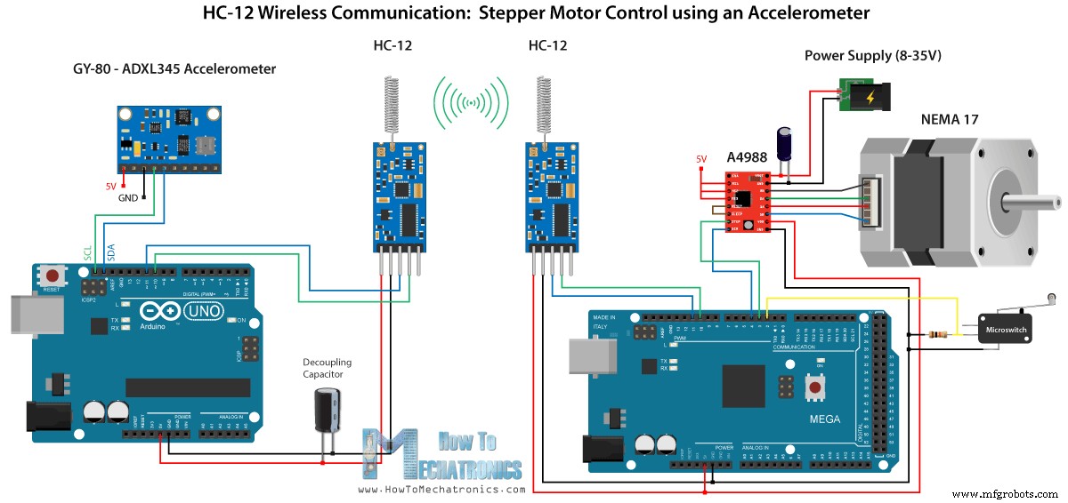
Agora vamos dar uma olhada no terceiro exemplo. Aqui controlamos a posição do motor de passo no segundo Arduino, usando o módulo acelerômetro no primeiro Arduino.
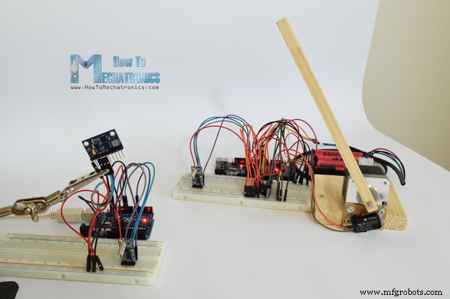
O circuito também contém um microinterruptor para encontrar a posição inicial do motor de passo a 0 graus.
Você pode obter os componentes necessários para este exemplo nos links abaixo:
- Módulo de comunicação sem fio HC-12 …………
- A4988 Motorista de Motor de Passo …………………………..
- Motor de passo NEMA 17 …………………………………
- Placa Arduino …………………………………………………..
- Breadboard e jump wires …………………………..
- Placa GY-80 com acelerômetro ADXL345 ………
Observe aqui que eu já tenho tutoriais detalhados sobre como conectar e usar tanto o acelerômetro quanto o motor de passo, então para este exemplo vou explicar apenas a parte HC-12 do código.
Primeiro Arduino – Código do transmissor:
/*   Arduino Long Range Wireless Communication using HC-12
     Example 03 - Stepper Motor Control using Accelerometer - Transmitter, Accelerometer
    by Dejan Nedelkovski, www.HowToMechatronics.com
*/

#include <SoftwareSerial.h>
#include <Wire.h>

SoftwareSerial HC12(10, 11); // HC-12 TX Pin, HC-12 RX Pin

float angle;
int lastAngle = 0;
int count = 0;
int angleSum = 0;

//--- Accelerometer Register Addresses
#define Power_Register 0x2D
#define X_Axis_Register_DATAX0 0x32 // Hexadecima address for the DATAX0 internal register.
#define X_Axis_Register_DATAX1 0x33 // Hexadecima address for the DATAX1 internal register.
#define Y_Axis_Register_DATAY0 0x34
#define Y_Axis_Register_DATAY1 0x35
#define Z_Axis_Register_DATAZ0 0x36
#define Z_Axis_Register_DATAZ1 0x37
int ADXAddress = 0x53;  //Device address in which is also included the 8th bit for selecting the mode, read in this case.
int X0, X1, X_out;
int Y0, Y1, Y_out;
int Z1, Z0, Z_out;
float Xa, Ya, Za;

void setup() {
  HC12.begin(9600);               // Open serial port to HC12
  Wire.begin(); // Initiate the Wire library
  Serial.begin(9600);
  delay(100);

  Wire.beginTransmission(ADXAddress);
  Wire.write(Power_Register); // Power_CTL Register
  // Enable measurement
  Wire.write(8); // Bit D3 High for measuring enable (0000 1000)
  Wire.endTransmission();
}
void loop() {
  // X-axis
  Wire.beginTransmission(ADXAddress); // Begin transmission to the Sensor
  //Ask the particular registers for data
  Wire.write(X_Axis_Register_DATAX0);
  Wire.write(X_Axis_Register_DATAX1);
  Wire.endTransmission(); // Ends the transmission and transmits the data from the two registers
  Wire.requestFrom(ADXAddress, 2); // Request the transmitted two bytes from the two registers
  if (Wire.available() <= 2) { //
    X0 = Wire.read(); // Reads the data from the register
    X1 = Wire.read();
    /* Converting the raw data of the X-Axis into X-Axis Acceleration
      - The output data is Two's complement
      - X0 as the least significant byte
      - X1 as the most significant byte */
    X1 = X1 << 8;
    X_out = X0 + X1;
    Xa = X_out / 256.0; // Xa = output value from -1 to +1, Gravity acceleration acting on the X-Axis
  }
  //Serial.print("Xa= ");
  //Serial.println(X_out);

  // Y-Axis
  Wire.beginTransmission(ADXAddress);
  Wire.write(Y_Axis_Register_DATAY0);
  Wire.write(Y_Axis_Register_DATAY1);
  Wire.endTransmission();
  Wire.requestFrom(ADXAddress, 2);
  if (Wire.available() <= 2) {
    Y0 = Wire.read();
    Y1 = Wire.read();
    Y1 = Y1 << 8;
    Y_out = Y0 + Y1;
    Ya = Y_out / 256.0;
  }

  // Combine X and Y values for getting the angle value from 0 to 180 degrees
  if (Y_out > 0) {
    angle = map(Y_out, 0, 256, 90, 0);
  }
  else if (Y_out < 0) {
    angle = map(Y_out, 256, 0, 90, 0);
    angle = 90 - angle;
  }
  if (X_out < 0 & Y_out < 0) {
    angle = 180;
  }
  if (X_out < 0 & Y_out >0) {
    angle = 0;
  }

  // float to int
  int angleInt = int(angle);
  // Makes 100 accelerometer readings and sends the average for smoother result
  angleSum = angleSum + angleInt;
  count++;
  if (count >= 100) {
    angleInt = angleSum / 100;
    angleSum = 0;
    count = 0;
    // Some more smoothing of acceleromter reading - sends the new angle only if it differes from the previous one by +-2
    if (angleInt > lastAngle + 2 || angleInt < lastAngle - 2) {
      Serial.println(angleInt);
      String angleString = String(angleInt);
      //sends the angle value with start marker "s" and end marker "e"
      HC12.print("s" + angleString + "e");
      delay(10);
      lastAngle = angleInt;
      angleSum = 0;
      count = 0;
    }
  }
}
Code language: Arduino (arduino)
Segundo Arduino – Código do receptor:
/*   Arduino Long Range Wireless Communication using HC-12
     Example 03 - Stepper Motor Control using Accelerometer - Receiver, Stepper Motor

    by Dejan Nedelkovski, www.HowToMechatronics.com
*/
#include <SoftwareSerial.h>

SoftwareSerial HC12(10, 11); // HC-12 TX Pin, HC-12 RX Pin

char incomingByte;
String readBuffer = "";

// defines pins numbers
const int dirPin = 4;
const int stepPin = 3;
const int button = 2;

int currentAngle = 0;
int lastAngle = 0;
int rotate = 0;

void setup() {
  Serial.begin(9600);             // Open serial port to computer
  HC12.begin(9600);               // Open serial port to HC12

  // Sets the two pins as Outputs
  pinMode(dirPin, OUTPUT);
  pinMode(stepPin, OUTPUT);
  // Microswitch input, with internal pull-up resistor activated
  pinMode(button, INPUT_PULLUP);
  delay(10);
  digitalWrite(dirPin, HIGH);
  boolean startingPosition = true;
  while (startingPosition) {
    digitalWrite(stepPin, HIGH);
    delayMicroseconds(200);
    digitalWrite(stepPin, LOW);
    delayMicroseconds(200);
    if (digitalRead(button) == LOW) {
      startingPosition = false;
    }
  }
  delay(100);
}
void loop() {
  readBuffer = "";
  boolean start = false;
  // Reads the incoming angle
  while (HC12.available()) {             // If HC-12 has data
    incomingByte = HC12.read();          // Store each icoming byte from HC-12
    delay(5);
    // Reads the data between the start "s" and end marker "e"
    if (start == true) {
      if (incomingByte != 'e') {
        readBuffer += char(incomingByte);    // Add each byte to ReadBuffer string variable
      }
      else {
        start = false;
      }
    }
    // Checks whether the received message statrs with the start marker "s"
    else if ( incomingByte == 's') {
      start = true; // If true start reading the message
    }
  }
  // Converts the string into integer
  currentAngle = readBuffer.toInt();
  // Makes sure it uses angles between 0 and 180
  if (currentAngle > 0 && currentAngle < 180) {
    // Convert angle value to steps (depending on the selected step resolution)
    // A cycle = 200 steps, 180deg = 100 steps ; Resolution: Sixteenth step x16
    currentAngle = map(currentAngle, 0, 180, 0, 1600);
    //Serial.println(currentAngle); // Prints the angle on the serial monitor
    digitalWrite(dirPin, LOW); // Enables the motor to move in a particular direction
    // Rotates the motor the amount of steps that differs from the previous positon
    if (currentAngle != lastAngle) {
      if (currentAngle > lastAngle) {
        rotate = currentAngle - lastAngle;
        for (int x = 0; x < rotate; x++) {
          digitalWrite(stepPin, HIGH);
          delayMicroseconds(400);
          digitalWrite(stepPin, LOW);
          delayMicroseconds(400);
        }
      }
      // rotate the other way
      if (currentAngle < lastAngle) {
        rotate = lastAngle - currentAngle;
        digitalWrite(dirPin, HIGH);        //Changes the rotations direction
        for (int x = 0; x < rotate; x++) {
          digitalWrite(stepPin, HIGH);
          delayMicroseconds(400);
          digitalWrite(stepPin, LOW);
          delayMicroseconds(400);
        }
      }
    }
    lastAngle = currentAngle;  // Remembers the current/ last positon
  }
}Code language: Arduino (arduino)
Descrição dos códigos:
Então, primeiro definimos os pinos e inicializamos os módulos na seção de configuração. Em seguida, lemos os valores dos eixos X e Y do acelerômetro e os mapeamos para valores de 0 a 180 graus. Os valores vindos do acelerômetro às vezes podem ficar instáveis ou tremer, então para suavizar o resultado usei o valor médio de cem leituras.
// Makes 100 accelerometer readings and sends the average for smoother result
  angleSum = angleSum + angleInt;
  count++;
  if (count >= 100) {
    angleInt = angleSum / 100;
    angleSum = 0;
    count = 0;
    // Some more smoothing of acceleromter reading - sends the new angle only if it differes from the previous one by +-2
    if (angleInt > lastAngle + 2 || angleInt < lastAngle - 2) {
      Serial.println(angleInt);
      String angleString = String(angleInt);
      //sends the angle value with start marker "s" and end marker "e"
      HC12.print("s" + angleString + "e");
      delay(10);
      lastAngle = angleInt;
      angleSum = 0;
      count = 0;
    }
  }Code language: Arduino (arduino)
Para suavizar ainda mais, enviarei o novo valor do ângulo somente se ele diferir do anterior por 2.
Observe aqui que ao enviar o ângulo para o módulo HC-12, também estou enviando o caractere “s” na frente, e o caractere “e” depois, o que me ajudará na hora de receber os dados no segundo Arduino.
No segundo Arduino esperamos até que o marcador inicial “s” chegue, então lemos o valor do ângulo até que o marcador final “e” chegue. Desta forma temos a certeza de que receberemos apenas o valor do ângulo.
// Reads the incoming angle
  while (HC12.available()) {             // If HC-12 has data
    incomingByte = HC12.read();          // Store each icoming byte from HC-12
    delay(5);
    // Reads the data between the start "s" and end marker "e"
    if (start == true) {
      if (incomingByte != 'e') {
        readBuffer += char(incomingByte);    // Add each byte to ReadBuffer string variable
      }
      else {
        start = false;
      }
    }
    // Checks whether the received message statrs with the start marker "s"
    else if ( incomingByte == 's') {
      start = true; // If true start reading the message
    }
  }Code language: Arduino (arduino)
Em seguida, convertemos o valor para inteiro e mapeamos o valor de 0 a 1600 passos, que corresponde à resolução de dezesseis passos selecionada no driver de passo A4988. Em seguida, giramos o motor de passo para o ângulo atual.
Então isso seria tudo para este tutorial do Arduino. Sinta-se à vontade para fazer qualquer pergunta na seção de comentários abaixo.
Motorista L298N – Interface Arduino, Como Funciona, Códigos, Esquemas
Como funciona o RFID e como fazer uma fechadura de porta RFID baseada em Arduino
Processo de manufatura
- Alcance de comunicação sem fio
- Por que o wireless de longo alcance alimentado por bateria causa interrupções
- Animação de LCD e jogos
- JX Wave Generator
- u-blox LEA-6H 02 Módulo GPS com Arduino e Python
- Scanner de temperatura infravermelho sem fio
- Comunicação Python3 e Arduino
- Rádio FM usando Arduino e RDA8057M
- Um sistema de detecção de queda baseado em Arduino, Windows e Azure
- ArduRadio AlarmClock