


Robô controlado por voz 2WD com Arduino e BitVoicer Server
Componentes e suprimentos
 |
| × | 1 | |||
| × | 1 | ||||
 |
| × | 1 | |||
| × | 1 | ||||
| × | 1 | ||||
| × | 1 | ||||
| × | 1 | ||||
 |
| × | 1 | |||
 |
| × | 4 | |||
 |
| × | 4 | |||
 |
| × | 4 | |||
 |
| × | 1 | |||
| × | 1 | ||||
 |
| × | 17 | |||
| × | 1 | ||||
| × | 1 |
Ferramentas e máquinas necessárias
 |
| |||
| ||||
|
Aplicativos e serviços online
|
Sobre este projeto
Neste tutorial, vou mostrar como construir um robô controlado por voz 2WD. Embora eu esteja controlando apenas motores CC para mover o robô, a mesma abordagem pode ser usada para motores de passo e servo motores de controle por voz, portanto, se você está planejando construir qualquer robô controlado por voz que execute movimentos mecânicos, este tutorial pode servir como referência para o seu projeto.
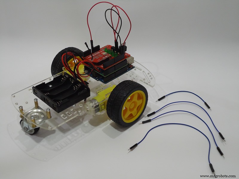
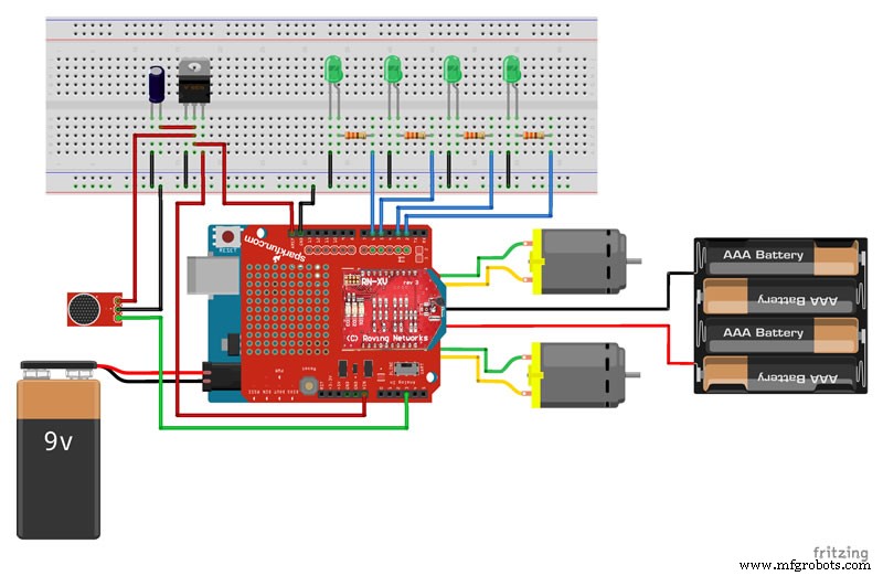
Para construir este robô, você basicamente precisará de um chassi de 2 rodas, uma placa Arduino, um protetor de driver de motor DC, uma licença do BitVoicer Server, um módulo WiFi e um microfone pré-amplificado. Em relação aos componentes, existe uma grande variedade no mercado e você pode obter os mesmos resultados usando diferentes combinações. Na Etapa 1, apresento alguns detalhes sobre alguns componentes usados no robô, portanto, se você precisar alterar alguns deles, basta procurar componentes com recursos semelhantes.
Os seguintes procedimentos serão executados para transformar comandos de voz em movimentos de robô:
- 1. As ondas de áudio serão capturadas e amplificadas pela placa Sparkfun Electret Breakout;
- 2. O sinal amplificado será digitalizado e armazenado em buffer no Arduino usando seu conversor analógico-digital (ADC);
- 3. As amostras de áudio serão transmitidas para o BitVoicer Server usando o módulo Microchip WiFi;
- 4. O BitVoicer Server processará o fluxo de áudio e reconhecerá a fala que ele contém;
- 5. A fala reconhecida será mapeada para comandos predefinidos que serão enviados para o Arduino;
- 6. O Arduino identificará o comando e definirá quais motores CC serão usados, por quanto tempo e em que velocidade;
- 7. O driver do motor será ativado para fornecer a tensão e a corrente necessárias para mover os motores.
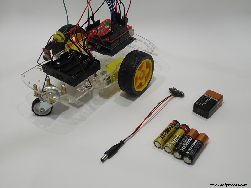
Lista de Materiais:
- Arduino UNO:~ U $ 25,00
- Escudo do driver do motor Pololu Dual MC33926:EUA 29,95
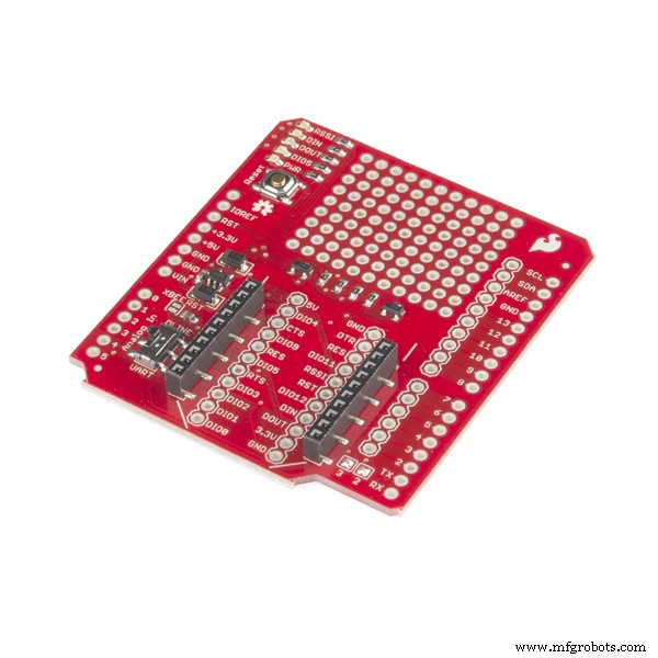
- SparkFun XBee Shield:U $ 14,95
- Módulo Microchip RN171VX com antena:U $ 34,95
- Breakout do microfone de eletreto SparkFun:U $ 7,95
- BitVoicer Server 1.0:U $ 8,90
- Chassi do carro robô 2WD:U $ 15,95
- Regulador de tensão Texas Instruments LM1117 (TO-220):~ U $ 1,95
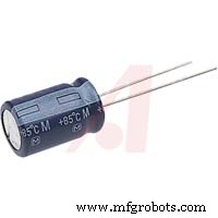
- Capacitor eletrolítico de 10μF:~ U $ 0,35
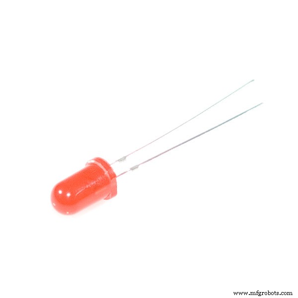
- 4 x LEDs:~ US 1,00
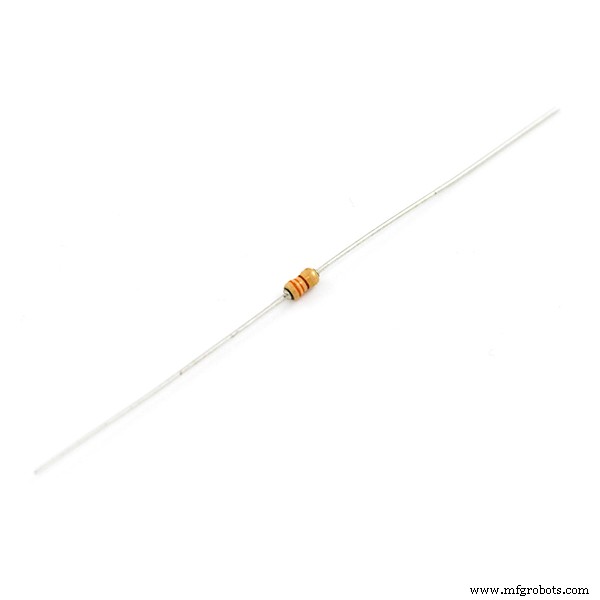
- 4 x 330 Ohms resistores:~ U $ 0,75
- 4 pilhas AA de 1,5 V:~ US 2,00
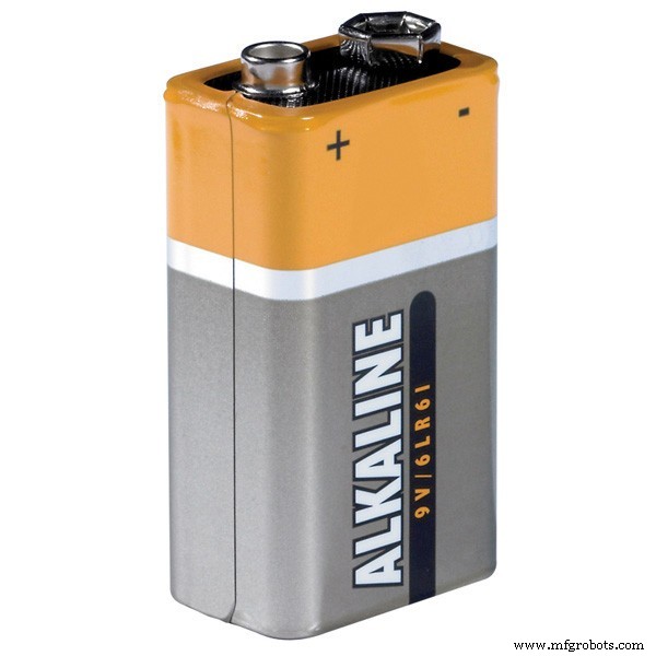
- Bateria 9V:~ US 2,00
- Adaptador de 9V para conector de cilindro:~ US 2,50
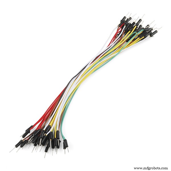
- Fios de jumpers e fios regulares:~ U $ 2,00
- Parafusos e braçadeira de plástico flexível para fixação
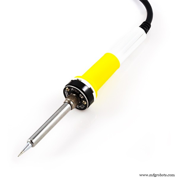
- Ferro de soldar e solda
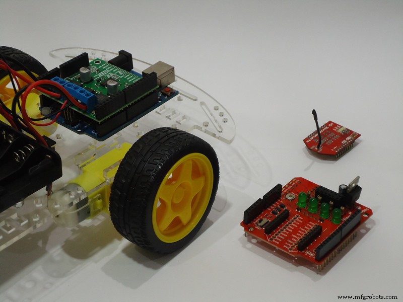
ETAPA 1:Conhecendo os componentes
Nesta etapa, dou algumas informações importantes sobre os componentes do robô e como prepará-los para a montagem.
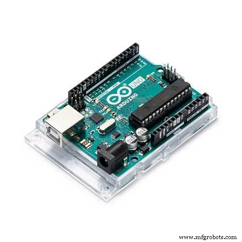
Em primeiro lugar, o coração do robô:um Arduino UNO R3. Embora eu esteja usando um Arduino UNO, você pode usar outras placas Arduino para montar seu robô. Decidi usar um Arduino UNO porque é, de longe, a placa Arduino mais popular e mais pessoas seriam capazes de reconstruir este robô. Se você tiver um Arduino DUE, também pode adicionar respostas de voz ao seu robô, como fiz neste tutorial.
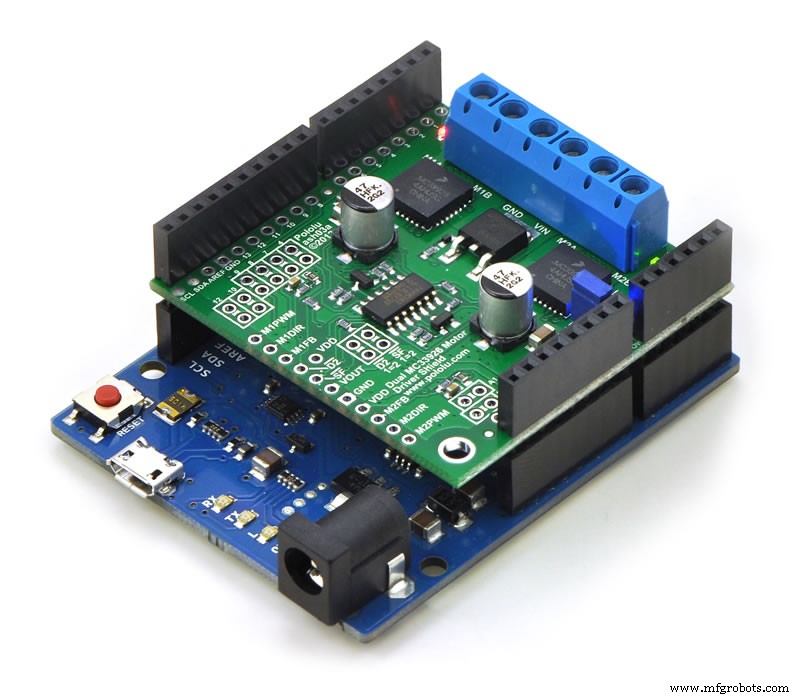
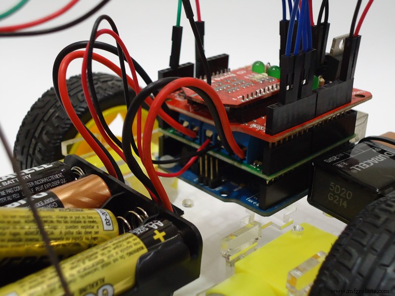
Para mover os motores DC, usei este escudo Pololu. É um driver de motor duplo capaz de controlar motores de 5 a 28 Vcc e fornecer até 3 A de corrente contínua por motor. Embora eu ache que este é um escudo muito bom, o que mais me impressionou nos produtos da Pololu é sua documentação clara e detalhada. Além disso, o Pololu oferece uma biblioteca Arduino que torna muito simples o controle dos motores. Você apenas tem que passar a velocidade e direção (valores negativos ou positivos) para o setSpeeds função. Se você optar por usar outro driver de motor DC, preste atenção aos pinos usados pelo driver porque eles não podem entrar em conflito com nenhum outro pino usado pelo robô. O escudo Pololu usa os seguintes pinos Arduino:digital 4, 7, 8, 9, 10 e 12; 0 e 1 analógico; chão; e 5V. O aspecto mais importante aqui é que apenas os pinos 9 e 10 são usados como pinos PWM e o temporizador usado para gerar pulsos nesses pinos não é o mesmo temporizador (temporizador 2 no UNO) usado pela classe BVSMic da BitSophia.
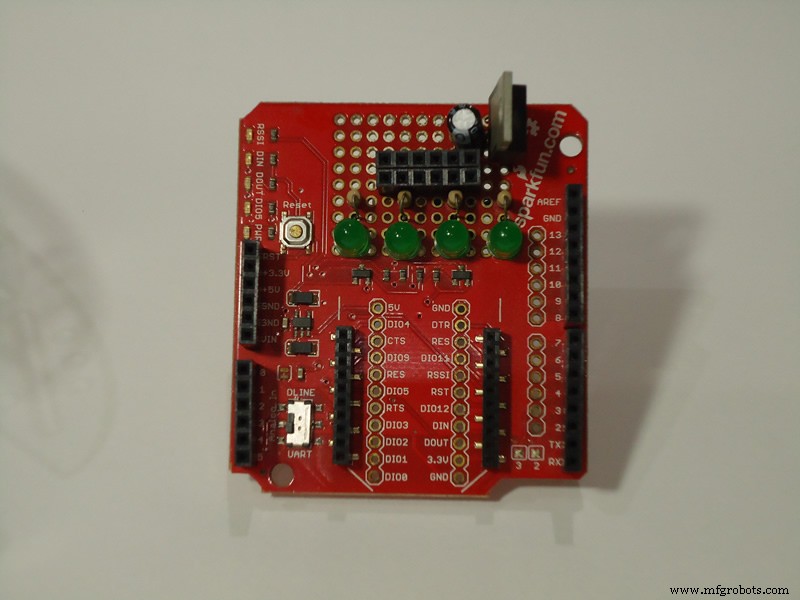
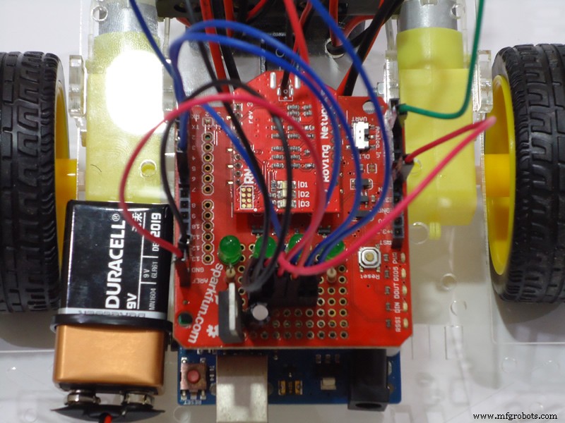
Para estabelecer comunicação com o servidor e acessar os serviços do BitVoicer Server, utilizo o módulo Microchip WiFi RN171VX. Duas características principais se destacam neste módulo:toda a comunicação pode ser feita através da porta serial de forma simples; e o módulo tem o mesmo formato que a maioria dos módulos XBee populares. Em outras palavras, se você já tem um escudo XBee, provavelmente não precisará comprar o escudo Sparkfun que uso neste robô.
Usar o escudo XBee com o módulo WiFi da Microchip tornou a montagem do robô muito fácil. No entanto, identifiquei um problema nesta combinação. É sabido que trabalhar com rádio é extremamente complexo e considerado por alguns como “magia vodu”. Bem, percebi que enquanto o adaptador WiFi está ligado e transmitindo dados, ocorre uma forte interferência no sinal de áudio medido pelo Arduino ADC. Não consegui identificar com precisão a fonte dessa interferência, mas tenho duas fontes possíveis:os consumos de corrente de pico do módulo (até 240mA) não estão sendo devidamente desacoplados e comprometem a tensão de referência fornecida ao Arduino ADC; ou o sinal emitido pela antena está sendo captado por alguns pinos expostos logo abaixo do módulo. Normalmente, os fabricantes de módulos WiFi instruem os projetistas a evitar colocar qualquer coisa (até mesmo planos terrestres) perto da antena, precisamente para evitar esse tipo de problema.
Para corrigir o problema descrito acima, soldei um regulador de voltagem de 3,3 V e um capacitor eletrolítico de 10μF à blindagem Sparkfun para que eles pudessem fornecer a voltagem de referência para o Arduino ADC. A mesma fonte de alimentação é usada pelo microfone de eletreto Sparkfun. Isso resolveu os problemas de volume de pico que eu estava vendo no BitVoicer Server Manager. Mesmo durante os períodos de silêncio, o nível de áudio estava chegando a 35 (0-100) no Monitor do Servidor. Se você vir a mesma coisa acontecendo em seu projeto, investigue o que está acontecendo com o sinal de áudio medido pelo Arduino ADC.
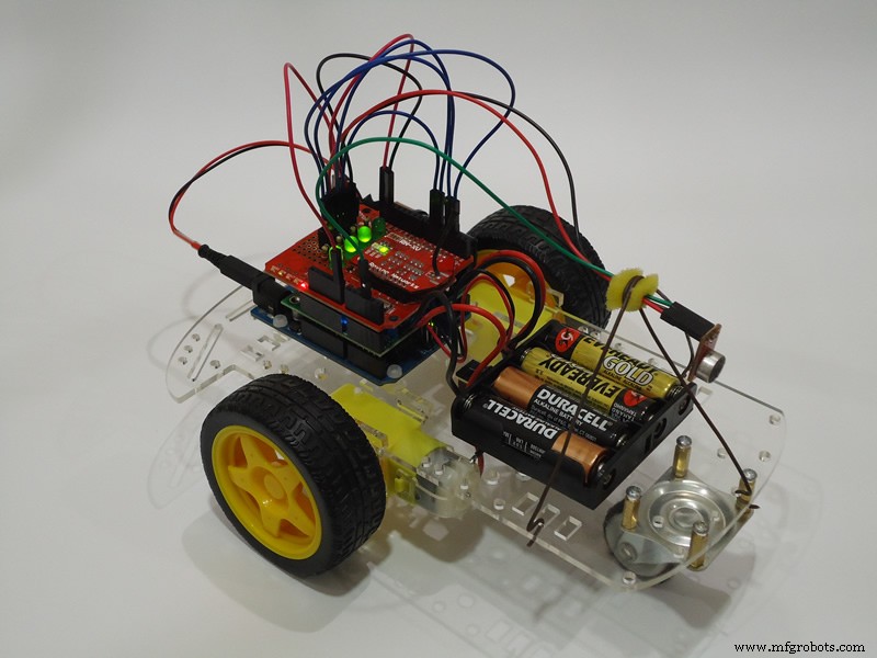
Decidi que também usaria o espaço de prototipagem disponível no escudo Sparkfun para soldar alguns LEDs que informam o status de algumas funcionalidades do BitVoicer Server. Na imagem abaixo, da esquerda para a direita, as seguintes informações são expostas pelos LEDs:
- Indica se o BitVoicer Server está rodando e / ou se a conexão permanece ativa;
- Indica se o serviço de encaminhamento de dados está em execução;
- Indica se um mecanismo de reconhecimento de voz foi atribuído ao Arduino;
- Indica se estamos no período de ativação da palavra de ativação. Este LED acende apenas quando a palavra de ativação é identificada.


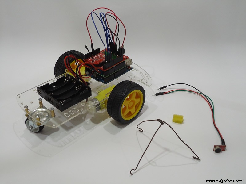
Em relação ao microfone de eletreto pré-amplificado, existem muitas opções disponíveis no mercado:Sparkfun, Adafruit, RoboCore, Hackerstore e provavelmente muitos outros. Para usar o código que estou postando neste tutorial, certifique-se de que o microfone que você está comprando seja analógico, a voltagem necessária esteja disponível em sua placa Arduino e a amplificação seja alta o suficiente (geralmente 100x para microfones de eletreto) para o ADC Arduino.
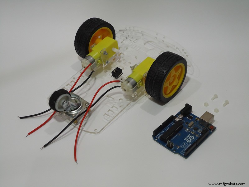
O chassi 2WD usado no robô é um dos mais baratos e populares do ebay. O kit completo contém uma plataforma de acrílico, duas rodas de plástico / borracha, uma roda 360º, dois motores DC com engrenagem (relação 1:48), um porta-bateria 4xAA, dois discos codificadores de velocidade e um conjunto de parafusos.
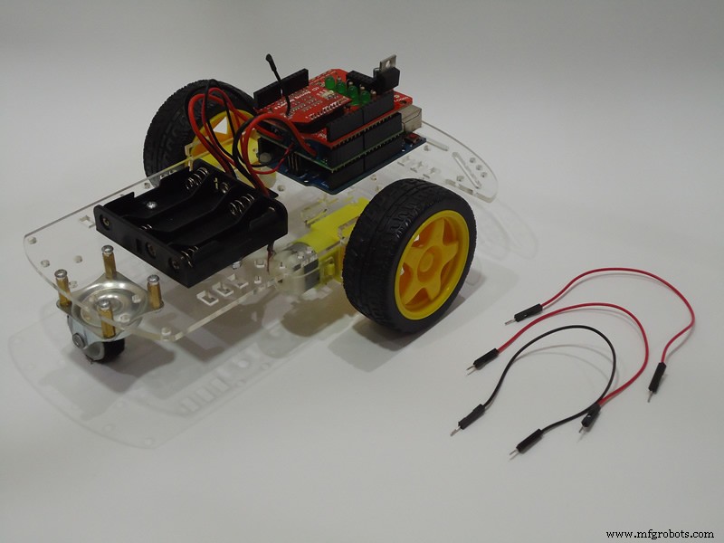
ETAPA 2:Montagem
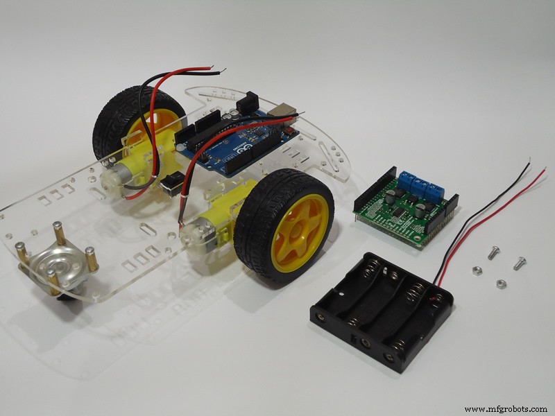
Vamos ao trabalho! Nesta etapa você deve montar todos os componentes no chassi conforme mostrado nas fotos abaixo.
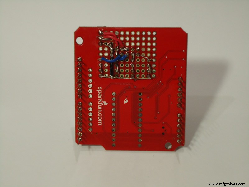
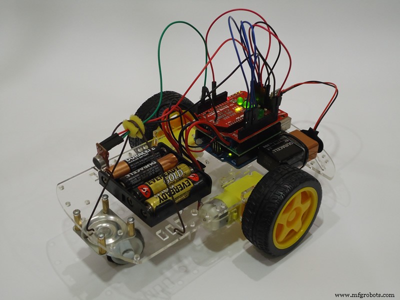
Se você não quiser soldar os LEDs e o regulador de tensão na blindagem do XBee, poderá montá-los em uma pequena placa de ensaio, conforme mostrado na imagem abaixo. Nesse caso, escolha uma placa de ensaio de tamanho reduzido para que você possa consertá-la em algum lugar do chassi sem problemas adicionais.

Nas fotos acima, você pode notar que fiz um suporte de fio de ferro para segurar o microfone. Você também pode ver que colei uma tira de tecido feltro em volta da roda 360º. Tomei essas duas medidas para tentar reduzir o ruído gerado pelo robô e captado pelo microfone quando o robô está se movendo. Até cortei um pequeno pedaço de esponja para isolar os fios do microfone do suporte. Claro que não foi 100% eficaz, mas reduziu um pouco o ruído e melhorou a precisão do reconhecimento de voz.
ETAPA 3:Configurando o Módulo WiFi
Como eu disse na Etapa 1, o módulo WiFi Microchip RN171VX pode ser totalmente operado através da porta serial. Isso torna extremamente fácil configurar o módulo porque todos os comandos são strings simples enviadas pela porta serial do Arduino. Basta enviar uma string contendo “$$$” para entrar no modo de comando, enviar os comandos e depois enviar uma string contendo “exit” para retornar ao modo de dados.
O código denominado Configuração do Módulo WiFi na parte inferior deste tutorial está o código que usei para configurar o módulo WiFi na minha rede doméstica. Você terá que alterar as partes do código marcadas como “XXXXXX” com informações de sua rede sem fio. Três comandos terão que ser alterados:
- definir wlan ssid XXXXXX :substitua XXXXXX pelo nome de sua rede (SSID);
- definir frase wlan XXXXXX :substitua XXXXXX por sua senha de rede;
- definir endereço IP XXXXXX :substitua o XXXXXX pelo endereço IP (estático) que você deseja definir para o seu módulo WiFi.
Na minha rede WiFi, o método de autenticação é WPA2-PSK. Se sua rede usa um método de autenticação diferente, você também terá que alterar o set wlan auth comando. Verifique a documentação do módulo WiFi (seção 4.3 Definir comandos) para descobrir qual valor é o correto para sua rede.
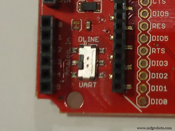
Existe um importante detalhes sobre o escudo Sparkfun e sua pequena chave (imagem abaixo). Para fazer o upload do código para o Arduino usando sua interface USB, a chave deve estar na posição DLINE. Para que o Arduino envie / receba dados por meio do módulo WiFi usando sua porta serial, a chave deve ser configurada para a posição UART. Isso é necessário porque o módulo WiFi e o chip USB no Arduino UNO usam a mesma porta serial no microcontrolador ATmega. Se a chave estiver configurada para UART e você tentar fazer upload do código para o Arduino, uma mensagem de erro será exibida no IDE do Arduino.
Para fazer o upload da Configuração do Módulo WiFi codificar para o Arduino e permitir que o Arduino configure o módulo WiFi, siga as etapas abaixo:
- 1. Coloque a chave na posição DLINE;
- 2. Abra o IDE do Arduino, cole e envie o código para o Arduino;
- 3. Assim que o upload terminar, você terá 5 segundos (atraso no início do código) para mudar a chave para a posição UART antes que os comandos sejam enviados ao módulo WiFi. Se o primeiro comando for perdido, nenhum dos outros funcionará. Nesse caso, simplesmente reinicie o Arduino para que o esboço possa ser executado novamente desde o início.
Durante a configuração do módulo, que leva cerca de 25 segundos, os LEDs do módulo piscarão de forma diferente do padrão. Neste momento você saberá que o módulo WiFi está sendo configurado.
Depois que o módulo estiver configurado, tente fazer o ping (Prompt de comando -> “ping [endereço IP]” -> pressione Enter) do módulo usando o endereço IP especificado em definir endereço IP comando. Se você não obtiver uma resposta do módulo, algo deu errado nas etapas anteriores.
ETAPA 4:planejando os movimentos do robô
Embora o robô tenha apenas dois motores CC, ele é capaz de realizar uma série de movimentos complexos. Para manter este tutorial o mais simples possível, optei por definir apenas cerca de três dezenas de movimentos básicos uniformes e alguns movimentos complexos formados pela combinação dos movimentos básicos.
Como vocês podem ver nas fotos da Etapa 2, não utilizo sensores de rotação nas rodas, sensores ultrassônicos ou qualquer outro tipo de sensor para medir a distância dos objetos ou a distância percorrida. Isso evita que o robô execute movimentos de alta precisão. No entanto, controlando apenas a direção e a velocidade dos motores, você pode atingir um nível de precisão bom o suficiente para mover o robô.
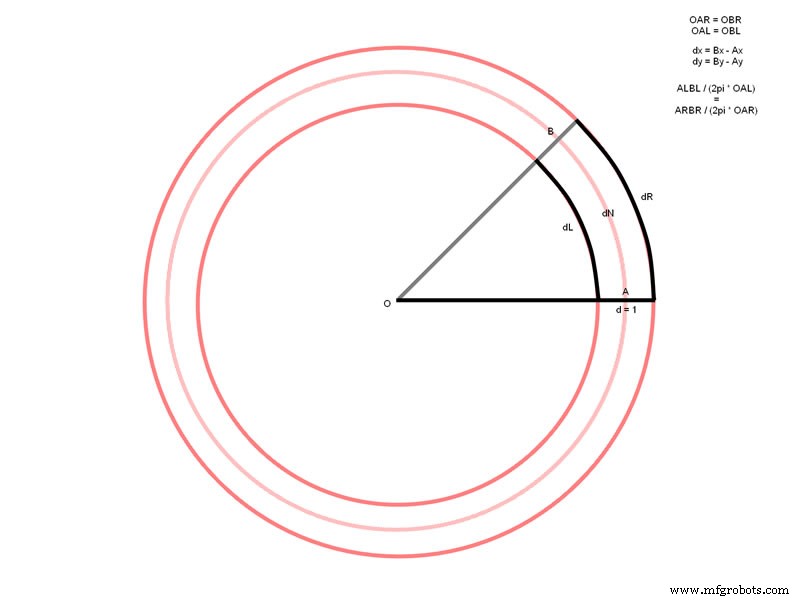
A primeira coisa que você precisa saber para poder calcular o tempo de execução necessário para cada movimento é a velocidade média do robô. To do that, place a tape measure parallel to the robot and activate both motors simultaneously for one or two seconds, measure the traveled distance and deduce the speed. In my configuration, I got 13.7 centimeters per second employing 62.5% of the maximum motor speed (250/400, see Pololu Arduino library). In other words, to move the robot 1 meter (100 cm) ahead, the motors had to be activated simultaneously for 7.299270… seconds. I have chosen to keep the time counting in the milliseconds resolution, but if you want to achieve higher movement precision, consider raising the resolution to microseconds. Long story short, to move the robot 1 meter, I have to activate both motors simultaneously for 7299 milliseconds. From this number, everything becomes rule of three for other distances. To perform arc or circular movements, one wheel has to move faster than the other. To turn the robot to the sides, only one wheel has to be activated or both in opposite directions (to turn on its own axis). Here you will have to use some trigonometry to figure out the distance traveled by each wheel and for how long each motor must be activated. A good starting point for these concepts can be found in the following links (I do not intend to go further on this here):http://rossum.sourceforge.net/papers/CalculationsForRobotics/CirclePath.htm and http://math.stackexchange.com/questions/60176/move-two-wheeled-robot-from-one-point-to-another.
As you can see at the end of the video below, I also make the robot “draw” some basic geometric forms (square, triangle and circle) on the floor. These movements are achieved by the combination of basic movements (e.g. go forward, turn, go forward, turn, etc.). The combination of these movements is made in the BitVoicer Server Voice Schema and you will not see them in the Arduino sketch presented in the next step.
STEP 5:Uploading the Code to the Arduino
In this step you will have to upload the sketch named Robot Source Code , located at the bottom of this tutorial, to the Arduino. You can also download the Arduino sketch from the link below. Remember that to send code to the Arduino you must set the switch on the Sparkfun shield to the DLINE position as described in Step 3. Before you upload the code, you must properly install the BitVoicer Server and the Pololu motor driver libraries into the Arduino IDE (Importing a .zip Library).
Robot Source Code :BVS_Demo3.ino
Some parts of this sketch are similar to parts I used in one of my previous tutorials and deals with the communication with BitVoicer Server (BVSP and BVSMic classes). In this tutorial, I will stick to the explanation of the new parts of the sketch. If you want to get more information about how to use the BVSP and the BVSMic classes, I suggest your refer to the tutorial I mentioned above.
- Constants Declaration :at the beginning of the sketch, I declare a series of constants used throughout the code. The group of constants with motor settings defines the default motor speeds and two direction constants. The Pololu motor driver library accepts values from -400 to +400 for the motor speed where zero means off. Negative values indicate reverse rotation or, if you have inverted the motor wires like me, forward rotation. The group of constants with command values refers to the commands that will be sent from BitVoicer Server. In this sketch I have defined only 40 basic commands of byte type, but more complex movements can be performed combining these commands.
- Execution Control Variables :five variables are defined at the beginning of the code to control the execution of commands (motorSpeed , cmdDuration , cmdStartTime , cmdRunning e lastFwdCmd ) The motorSpeed variable holds the current motor speed. This variable is updated with one of the default values defined by the speed constants if the Arduino receives a command from BitVoicer Server to update the motor speeds. The cmdDuration variable holds the total duration of the current command. This variable is checked against the cmdStartTime variable in all iterations of the loop function if cmdRunning is true . If the command execution time has expired, the RunCommand function is called to stop the motors. The lastFwdCmd variable holds the last “go/move forward” command. This variable is used to know the last traveled distance so the “come back” command can be executed. Note that to use this command you must first tell the robot to turn around.
- WiFi Connection :at the end of the sketch I define two functions to connect and disconnect from BitVoicer Server (Connect and Disconnect ) These functions put the Microchip WiFi module into command mode, open or close a TCP/IP connection and return the module into data mode. Inside the loop function, if the connected variable is not true , I call the Connect função. If the BVSP class reports the server status has expired, in other words, no answer has been received for the last status request, I assume the connection has been lost and I call the Disconnect função. This will force a new connection attempt in the next loop iteration.
- RunCommand function :this function is called every time a command is received from BitVoicer Server. It takes a byte value that corresponds to one of the basic commands defined by the constants at the beginning of the sketch. Each basic command is identified inside the switch so the appropriate motor speeds can be set as well as the command duration. At the end of the function, the cmdRunning variable is set to true and the time returned by the millis function is stored in the cmdStartTime variável. This allows the Arduino to control the command execution as described above. The times, in milliseconds, for each command were obtained as described in the previous step.
STEP 6:Setting Up BitVoicer Server
In this step you have to build the BitVoicer Server Voice Schema with the sentences to be recognized and the commands that will be sent to the Arduino. At the end of this step, there are two links to files containing all BitVoicer Server Solution Objects used in this tutorial. If you do not want to create all solution objects one-by-one, you can import them (Importing Solution Objects) using these files.
Before you start building the Voice Schema, you have to create a device that will represent the Arduino in BitVoicer Server. Create a mixed device and name it ArduinoUnoWiFi. In the Communication tab, select TCP/IP and enter the IP address assigned to the WiFi module in Step 3. In the Cues tab, enable the Start of Activated Period and End of Activated Period cues. Select Int16 SendData commands for both cues and select the ArduinoUnoWiFi device as the target of the commands. In the Data field, enter 1 for the Start of Activated Period cue and 0 for the End of Activated Period cue. These cues will make the Arduino turn on one LED every time the activation word is recognized. When the activated period (defined in the Voice Schema) expires, this LED will turn off.
Now let’s build the Voice Schema. Although the robot has only 40 basic commands, you may want to create many word combinations that trigger the same command. As an example, you may want the sentences “move forward one meter” and “go forward one meter” to trigger the same command. Besides, you may want to create complex commands as “do a square” that will trigger a series of temporized commands in sequence. Because of that, your Voice Schema can grow a lot and have many more than 40 basic commands. BitVoicer Server supports unlimited sentences so you can define as many sentences as you need (mine ended up with more than 80 sentences). Here I would like to give two tips:create a default command in the BitVoicer Server Manager Options; and copy and paste duplicated commands from one sentence to the others.
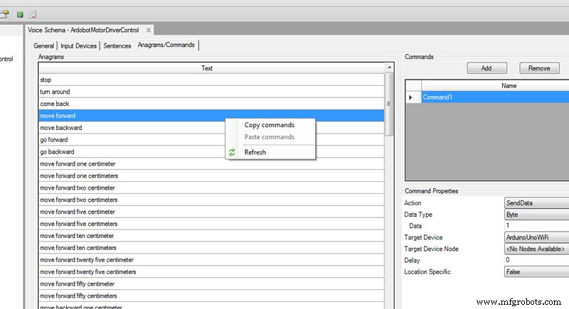
Sentence commands will send byte data types to the Arduino. Use the constants defined at the beginning of the sketch to know which value must be sent for each command. Complex commands will send many values in sequence and you will have to control the interval (delay) between them so that no value is sent while the previous command is under execution. Use the delay field to set the interval between commands.
Solution Object Files :
Device.sof
VoiceSchema.sof
STEP 7:Conclusion
Now all you have to do is to put in the AA batteries and connect the 9V battery to the Arduino power jack for your robot to come to life! After you upload the code to the Arduino, do not forget to turn the switch mounted on the Sparkfun shield to the UART position. Otherwise, the WiFi module will not receive any data sent from the Arduino serial port.
After you turn the robot on, the status LEDs will take a little while before they light up. You will see the WiFi module starting communication and when the TCP/IP connection is established, one of the module LEDs will turn solid on. After a few instants, three out of the four status LEDs will light up as well. This means one speech recognition engine has been assigned to the Arduino. From now on, the robot is ready to take commands.
After some testing with the robot, I was pretty satisfied with the speech recognition, although it did not recognize 100% of the commands all the times. In this aspect BitVoicer Server really surprised me. However, I was not that much satisfied with the precision of the robot’s movements. To fix this problem, I would have to add rotation sensors to the wheels. The chassis kit I used in the robot already comes with decoder disks that can be attached to the gear. Applying sensors to these disks would allow me to move the robot based on the real traveled distance so that its movement would be more precise. I could also add ultrasonic sensors to avoid bumping around my furniture. I will probably do that someday, but for now, I leave that up to you.
See you next time!
Código
- WiFi Module Setup
- Robot Source Code
WiFi Module SetupArduino
Configures the Microchip WiFi RN171VX module using the Arduino serial port.void setup() { Serial.begin(115200); pinMode(13, OUTPUT); atraso (5000); Serial.print("$$$"); atraso (1000); Serial.println("set wlan auth 4"); atraso (1000); Serial.println("set wlan phrase XXXXXX"); atraso (1000); Serial.println("set wlan ssid XXXXXX"); atraso (1000); Serial.println("set wlan channel 0"); atraso (1000); Serial.println("set wlan join 1"); atraso (1000); Serial.println("set wlan tx 0"); atraso (1000); Serial.println("set ip dhcp 0"); atraso (1000); Serial.println("set ip address XXXXXX"); atraso (1000); Serial.println("set comm remote 0"); atraso (1000); Serial.println("set comm close 0"); atraso (1000); Serial.println("set comm open 0"); atraso (1000); Serial.println("set comm size 500"); atraso (1000); Serial.println("set comm time 50"); atraso (1000); Serial.println("set uart baud 115200"); atraso (1000); Serial.println("set uart flow 0"); atraso (1000); Serial.println("save"); atraso (1000); Serial.println("exit"); atraso (1000); digitalWrite(13, LOW);}void loop() { } Robot Source CodeArduino
Controls the robot movements, captures audio, manages the TCP/IP connection and communicates with BitVoicer Server.#include#include #include // Defines the Arduino pins that will be used to control// LEDs and capture audio#define BVS_RUNNING 2#define BVS_SRE 5#define BVS_DATA_FWD 3#define BVS_ACT_PERIOD 6#define BVSM_AUDIO_INPUT 3// Defines the constants that will be passed as parameters to // the BVSP.begin functionconst unsigned long STATUS_REQUEST_INTERVAL =2000;const unsigned long STATUS_REQUEST_TIMEOUT =1000;// Defines the size of the mic bufferconst int MIC_BUFFER_SIZE =64;// Initializes a new global instance of the BVSP classBVSP bvsp =BVSP();// Initializes a new global instance of the BVSMic classBVSMic bvsm =BVSMic();// Initializes a new global instance of the // DualMC33926MotorShield classDualMC33926MotorShield ms =DualMC33926MotorShield();// Creates a buffer that will be used to read recorded samples // from the BVSMic classbyte micBuffer[MIC_BUFFER_SIZE];// Creates a global variable that indicates whether the // Arduino is connected to BitVoicer Serverboolean connected =false;// Defines some constants for the motor settingsconst int SPEED_STOP =0;const int SPEED_SLOW =100;const int SPEED_NORMAL =250;const int SPEED_FAST =400;const int DIRECTION_FRONT =-1;const int DIRECTION_BACK =1;// Declares a global variables to hold the current motor speed.// The default is SPEED_NORMAL, but there are voice // commands that change this setting.int motorSpeed =SPEED_NORMAL;// Stores the command duration in millisecondsunsigned long cmdDuration =0;// Stores the time the command started runningunsigned long cmdStartTime =0;// Stores whether a command is running or notbool cmdRunning =false;// Stores the last MOVE_FORWARD command. This variable // is used only for the COME_BACK command.byte lastFwdCmd =0;// Defines some constants for command names/values// Just to make the code more readableconst byte CMD_STOP =0;const byte CMD_MOVE_FORWARD =1;const byte CMD_MOVE_FORWARD_1_CM =2;const byte CMD_MOVE_FORWARD_2_CM =3;const byte CMD_MOVE_FORWARD_5_CM =4;const byte CMD_MOVE_FORWARD_10_CM =5;const byte CMD_MOVE_FORWARD_25_CM =6;const byte CMD_MOVE_FORWARD_50_CM =7;const byte CMD_MOVE_FORWARD_1_M =8;const byte CMD_MOVE_BACKWARD =9;const byte CMD_MOVE_BACKWARD_1_CM =10;const byte CMD_MOVE_BACKWARD_2_CM =11;const byte CMD_MOVE_BACKWARD_5_CM =12;const byte CMD_MOVE_BACKWARD_10_CM =13;const byte CMD_MOVE_BACKWARD_25_CM =14;const byte CMD_MOVE_BACKWARD_50_CM =15;const byte CMD_MOVE_BACKWARD_1_M =16;const byte CMD_TURN_AROUND =17;const byte CMD_TURN_AROUND_RIGHT =18;const byte CMD_TURN_AROUND_LEFT =19;const byte CMD_DO_360 =20;const byte CMD_TURN_RIGHT =21;const byte CMD_TURN_RIGHT_10 =22;const byte C MD_TURN_RIGHT_25 =23;const byte CMD_TURN_RIGHT_45 =24;const byte CMD_TURN_LEFT =25;const byte CMD_TURN_LEFT_10 =26;const byte CMD_TURN_LEFT_25 =27;const byte CMD_TURN_LEFT_45 =28;const byte CMD_DO_CIRCLE =29;const byte CMD_COME_BACK =30;const byte CMD_MOVE_FORWARD_2_M =31;const byte CMD_MOVE_FORWARD_3_M =32;const byte CMD_MOVE_BACKWARD_2_M =33;const byte CMD_MOVE_BACKWARD_3_M =34;const byte CMD_SET_SPEED_SLOW =35;const byte CMD_SET_SPEED_NORMAL =36;const byte CMD_SET_SPEED_FAST =37;const byte CMD_TURN_LEFT_45_BACKWARD =38;const byte CMD_TURN_RIGHT_45_BACKWARD =39;void setup(){ // Starts serial communication at 115200 bps Serial.begin(115200); // Sets the Arduino pin modes pinMode(BVS_RUNNING, OUTPUT); pinMode(BVS_SRE, OUTPUT); pinMode(BVS_DATA_FWD, OUTPUT); pinMode(BVS_ACT_PERIOD, OUTPUT); AllLEDsOff(); // Sets the Arduino serial port that will be used for // communication, how long it will take before a status request // times out and how often status requests should be sent to // BitVoicer Server bvsp.begin(Serial, STATUS_REQUEST_TIMEOUT, STATUS_REQUEST_INTERVAL); // Sets the function that will handle the frameReceived // event bvsp.frameReceived =BVSP_frameReceived; // Prepares the BVSMic class timer bvsm.begin(); // Prepares the motor shield class (pins and timer1) ms.init();}void loop() { // If it is not connected to the server, opens a TCP/IP // connection, sets connected to true and resets the BVSP // class if (!connected) { Connect(Serial); connected =true; bvsp.reset(); } // Checks if the status request interval has elapsed and if it // has, sends a status request to BitVoicer Server bvsp.keepAlive(); // Checks if there is data available at the serial port buffer // and processes its content according to the specifications // of the BitVoicer Server Protocol bvsp.receive(); // Gets the respective status from the BVSP class and sets // the LEDs on or off digitalWrite(BVS_RUNNING, bvsp.isBVSRunning()); digitalWrite(BVS_DATA_FWD, bvsp.isDataFwdRunning()); // Checks if there is a SRE assigned to the Arduino if (bvsp.isSREAvailable()) { // Turns on the SRE available LED digitalWrite(BVS_SRE, HIGH); // If the BVSMic class is not recording, sets up the audio // input and starts recording if (!bvsm.isRecording) { bvsm.setAudioInput(BVSM_AUDIO_INPUT, EXTERNAL); bvsm.startRecording(); } // Checks if the BVSMic class has available samples if (bvsm.available) { // Makes sure the inbound mode is STREAM_MODE before // transmitting the stream if (bvsp.inboundMode ==FRAMED_MODE) bvsp.setInboundMode(STREAM_MODE); // Reads the audio samples from the BVSMic class int bytesRead =bvsm.read(micBuffer, MIC_BUFFER_SIZE); // Sends the audio stream to BitVoicer Server bvsp.sendStream(micBuffer, bytesRead); } } else { // There is no SRE available // Turns off the SRE and ACT_PERIOD LEDs digitalWrite(BVS_SRE, LOW); digitalWrite(BVS_ACT_PERIOD, LOW); // If the BVSMic class is recording, stops it if (bvsm.isRecording) bvsm.stopRecording(); } // If the status has timed out, the connection is considered // lost if (bvsp.hasStatusTimedOut()) { // If the BVSMic is recording, stops it if (bvsm.isRecording) bvsm.stopRecording(); // Closes the TCP/IP connection Disconnect(Serial); AllLEDsOff(); connected =false; } // If a command is running, checks if its duration has // expired. If it has, stop the motors. if (cmdRunning) if (millis() - cmdStartTime>=cmdDuration) RunCommand(CMD_STOP);}// Handles the frameReceived eventvoid BVSP_frameReceived(byte dataType, int payloadSize){ // Performs the appropriate actions based on the frame // data type. If the data type is byte, it is a command. // If the data type is int, changes the activated // period LED. switch (dataType) { case DATA_TYPE_BYTE:RunCommand(bvsp.getReceivedByte()); pausa; case DATA_TYPE_INT16:digitalWrite(BVS_ACT_PERIOD, bvsp.getReceivedInt16()); pausa; }}// Runs the command received from the servervoid RunCommand(byte cmd){ switch (cmd) { case CMD_STOP:ms.setSpeeds(SPEED_STOP, SPEED_STOP); cmdRunning =false; Retorna; case CMD_MOVE_FORWARD:lastFwdCmd =cmd; ms.setSpeeds( motorSpeed * DIRECTION_FRONT, motorSpeed * DIRECTION_FRONT); cmdDuration =60000; pausa; case CMD_MOVE_FORWARD_1_CM:lastFwdCmd =cmd; ms.setSpeeds( motorSpeed * DIRECTION_FRONT, motorSpeed * DIRECTION_FRONT); cmdDuration =23; pausa; case CMD_MOVE_FORWARD_2_CM:lastFwdCmd =cmd; ms.setSpeeds( motorSpeed * DIRECTION_FRONT, motorSpeed * DIRECTION_FRONT); cmdDuration =47; pausa; case CMD_MOVE_FORWARD_5_CM:lastFwdCmd =cmd; ms.setSpeeds( motorSpeed * DIRECTION_FRONT, motorSpeed * DIRECTION_FRONT); cmdDuration =117; pausa; case CMD_MOVE_FORWARD_10_CM:lastFwdCmd =cmd; ms.setSpeeds( motorSpeed * DIRECTION_FRONT, motorSpeed * DIRECTION_FRONT); cmdDuration =234; pausa; case CMD_MOVE_FORWARD_25_CM:lastFwdCmd =cmd; ms.setSpeeds( motorSpeed * DIRECTION_FRONT, motorSpeed * DIRECTION_FRONT); cmdDuration =468; pausa; case CMD_MOVE_FORWARD_50_CM:lastFwdCmd =cmd; ms.setSpeeds( motorSpeed * DIRECTION_FRONT, motorSpeed * DIRECTION_FRONT); cmdDuration =1170; pausa; case CMD_MOVE_FORWARD_1_M:lastFwdCmd =cmd; ms.setSpeeds( motorSpeed * DIRECTION_FRONT, motorSpeed * DIRECTION_FRONT); cmdDuration =2339; pausa; case CMD_MOVE_FORWARD_2_M:lastFwdCmd =cmd; ms.setSpeeds( motorSpeed * DIRECTION_FRONT, motorSpeed * DIRECTION_FRONT); cmdDuration =4678; pausa; case CMD_MOVE_FORWARD_3_M:lastFwdCmd =cmd; ms.setSpeeds( motorSpeed * DIRECTION_FRONT, motorSpeed * DIRECTION_FRONT); cmdDuration =7018; pausa; case CMD_MOVE_BACKWARD:ms.setSpeeds( motorSpeed * DIRECTION_BACK, motorSpeed * DIRECTION_BACK); cmdDuration =60000; pausa; case CMD_MOVE_BACKWARD_1_CM:ms.setSpeeds( motorSpeed * DIRECTION_BACK, motorSpeed * DIRECTION_BACK); cmdDuration =23; pausa; case CMD_MOVE_BACKWARD_2_CM:ms.setSpeeds( motorSpeed * DIRECTION_BACK, motorSpeed * DIRECTION_BACK); cmdDuration =47; pausa; case CMD_MOVE_BACKWARD_5_CM:ms.setSpeeds( motorSpeed * DIRECTION_BACK, motorSpeed * DIRECTION_BACK); cmdDuration =117; pausa; case CMD_MOVE_BACKWARD_10_CM:ms.setSpeeds( motorSpeed * DIRECTION_BACK, motorSpeed * DIRECTION_BACK); cmdDuration =234; pausa; case CMD_MOVE_BACKWARD_25_CM:ms.setSpeeds( motorSpeed * DIRECTION_BACK, motorSpeed * DIRECTION_BACK); cmdDuration =468; pausa; case CMD_MOVE_BACKWARD_50_CM:ms.setSpeeds( motorSpeed * DIRECTION_BACK, motorSpeed * DIRECTION_BACK); cmdDuration =1170; pausa; case CMD_MOVE_BACKWARD_1_M:ms.setSpeeds( motorSpeed * DIRECTION_BACK, motorSpeed * DIRECTION_BACK); cmdDuration =2339; pausa; case CMD_MOVE_BACKWARD_2_M:ms.setSpeeds( motorSpeed * DIRECTION_BACK, motorSpeed * DIRECTION_BACK); cmdDuration =4678; pausa; case CMD_MOVE_BACKWARD_3_M:ms.setSpeeds( motorSpeed * DIRECTION_BACK, motorSpeed * DIRECTION_BACK); cmdDuration =7017; pausa; case CMD_TURN_AROUND:ms.setSpeeds( motorSpeed * DIRECTION_FRONT, motorSpeed * DIRECTION_BACK); cmdDuration =540; pausa; case CMD_TURN_AROUND_RIGHT:ms.setSpeeds( motorSpeed * DIRECTION_FRONT, motorSpeed * DIRECTION_BACK); cmdDuration =540; pausa; case CMD_TURN_AROUND_LEFT:ms.setSpeeds( motorSpeed * DIRECTION_BACK, motorSpeed * DIRECTION_FRONT); cmdDuration =540; pausa; case CMD_DO_360:ms.setSpeeds( motorSpeed * DIRECTION_FRONT, motorSpeed * DIRECTION_BACK); cmdDuration =1065; pausa; case CMD_TURN_RIGHT:ms.setSpeeds(motorSpeed * DIRECTION_FRONT, 0); cmdDuration =503; pausa; case CMD_TURN_RIGHT_10:ms.setSpeeds(motorSpeed * DIRECTION_FRONT, 0); cmdDuration =56; pausa; case CMD_TURN_RIGHT_25:ms.setSpeeds(motorSpeed * DIRECTION_FRONT, 0); cmdDuration =140; pausa; case CMD_TURN_RIGHT_45:ms.setSpeeds(motorSpeed * DIRECTION_FRONT, 0); cmdDuration =252; pausa; case CMD_TURN_LEFT:ms.setSpeeds(0, motorSpeed * DIRECTION_FRONT); cmdDuration =503; pausa; case CMD_TURN_LEFT_10:ms.setSpeeds(0, motorSpeed * DIRECTION_FRONT); cmdDuration =56; pausa; case CMD_TURN_LEFT_25:ms.setSpeeds(0, motorSpeed * DIRECTION_FRONT); cmdDuration =140; pausa; case CMD_TURN_LEFT_45:ms.setSpeeds(0, motorSpeed * DIRECTION_FRONT); cmdDuration =252; pausa; case CMD_DO_CIRCLE:ms.setSpeeds( SPEED_NORMAL * DIRECTION_FRONT, SPEED_NORMAL * DIRECTION_FRONT * 0.60); cmdDuration =4587; pausa; case CMD_COME_BACK:RunCommand(lastFwdCmd); Retorna; case CMD_SET_SPEED_SLOW:motorSpeed =SPEED_SLOW; Retorna; case CMD_SET_SPEED_NORMAL:motorSpeed =SPEED_NORMAL; Retorna; case CMD_SET_SPEED_FAST:motorSpeed =SPEED_FAST; Retorna; case CMD_TURN_LEFT_45_BACKWARD:ms.setSpeeds(motorSpeed * DIRECTION_BACK, 0); cmdDuration =252; pausa; case CMD_TURN_RIGHT_45_BACKWARD:ms.setSpeeds(0, motorSpeed * DIRECTION_BACK); cmdDuration =252; pausa; } // Sets the command start time cmdStartTime =millis(); // Sets cmdRunning to true cmdRunning =true;}// Opens a TCP/IP connection with the BitVoicer Servervoid Connect(HardwareSerial &serialPort){ serialPort.print("$$$"); atraso (500); // Use the IP address of the server and the TCP port set // in the server properties serialPort.println("open 192.168.0.11 4194"); atraso (1000); serialPort.println("exit"); delay(500);}// Closes the TCP/IP connection with the BitVoicer Servervoid Disconnect(HardwareSerial &serialPort){ serialPort.print("$$$"); atraso (500); serialPort.println("close"); atraso (1000); serialPort.println("exit"); delay(500);}// Turns all LEDs offvoid AllLEDsOff(){ digitalWrite(BVS_RUNNING, LOW); digitalWrite(BVS_SRE, LOW); digitalWrite(BVS_DATA_FWD, LOW); digitalWrite(BVS_ACT_PERIOD, LOW);}
Esquemas
Processo de manufatura
- Robô Raspberry Pi controlado por Bluetooth
- Construa seu robô de streaming de vídeo controlado pela Internet com Arduino e Raspberry Pi
- Sistema de atendimento usando Arduino e RFID com Python
- Diversão do giroscópio com anel NeoPixel
- Brinquedo controlado pelo Android usando Raspberry Motor Shield
- Obstáculos para evitar o robô com servo motor
- Controle de um robô Roomba com Arduino e dispositivo Android
- Braço robótico controlado por Nunchuk (com Arduino)
- Robô controlado por fala
- Dispositivos Bluetooth controlados por voz com OK Google