


IoT usando ESP8266-01 e Arduino
Componentes e suprimentos
 |
| × | 1 | |||
 |
| × | 1 | |||
 |
| × | 1 | |||
| × | 1 | ||||
 |
| × | 2 | |||
 |
| × | 1 | |||
 |
| × | 1 | |||
 |
| × | 2 | |||
 |
| × | 1 |
Ferramentas e máquinas necessárias
| |
| |||
 |
| |||
 |
|
Aplicativos e serviços online
| ||||
 |
| |||
|
Sobre este projeto
Introdução
Hoje, vamos construir um dispositivo que se conecta à internet e permite ao usuário controlar sua casa remotamente através de wi-fi. usaremos a placa Arduino (qualquer modelo fará bem o trabalho) com o módulo wifi ESP8266-01 para fazer este dispositivo. Vamos começar!
O que é uma casa inteligente?
Cenário de trabalho

O ControlPanel
Vamos construir uma página web simples que funcionará como um painel de controle para que o usuário controle qualquer eletrodoméstico conectado ao nosso sistema. Para construir a página da web, usaremos:
- HTML
- CSS
- Jquery
O Hardware Embutido
a página da web envia alguns pedidos para o ESP8266-01 que está funcionando como um servidor da web conectado à placa do Arduino. E de acordo com os dados de entrada, a placa Arduino realizará algumas ações como acender a lâmpada, desligar a TV e nesta parte usaremos:
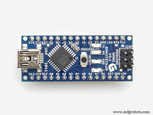
- Arduino
- ESP8266-01
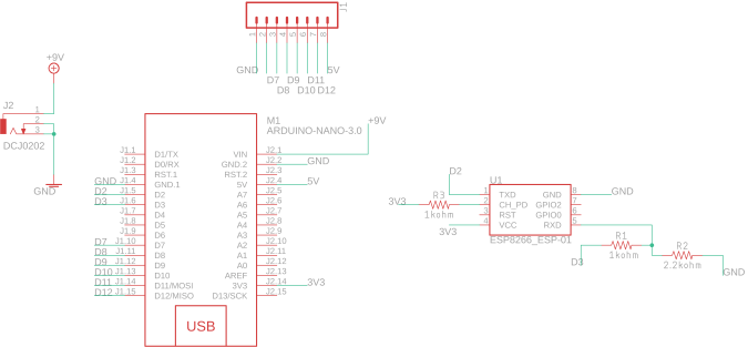
Primeiros passos com o ESP8266-01
Como dissemos antes, precisamos de nossa placa Arduino para nos conectarmos à Internet, mas o Arduino Nano, a versão que usamos hoje, não tem esse recurso. Portanto, usaremos o módulo wi-fi ESP8266-01 para adicionar o recurso wi-fi à nossa pequena placa Arduino.
existem muitos modelos de módulos de wifi ESP por aí, qual deles devo escolher ?! Bem, quase todos os módulos wi-fi da família ESP por aí farão bem o trabalho, mas cada um tem seus próprios recursos e especificações. Eu encorajo você a olhar as especificações e características de cada um para escolher o mais adequado às suas necessidades.
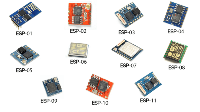
De acordo com minhas necessidades, descobri que o ESP8266-01 é o mais adequado e isso por vários motivos. É muito famoso na comunidade de fabricantes. Como resultado, ele obteve uma comunidade online muito sólida, onde você pode encontrar uma resposta para quase qualquer pergunta ou problema que você enfrentar com este pequeno módulo incrível. Além disso, seu preço é muito barato (cerca de US $ 1,5).
Além disso, é muito fácil de usar com a placa Arduino, pois é um módulo wi-fi Serial que pode se comunicar com a placa Arduino pela comunicação serial. Ele tem um microcontrolador embutido, o que significa que você pode usá-lo como um microcontrolador autônomo e módulo wi-fi em um combo, o que é muito legal. Possui dois GPIOs integrados. Apenas com $ 1,5, você terá todos esses recursos que são super legais, na verdade. Vamos dar uma olhada mais de perto neste módulo.
Pinagem ESP8266-01
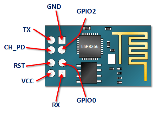
- VCC: conecte à fonte de alimentação de +3,3 V. não o conecte a uma fonte de 5 V, ele será danificado .
- GND: -ve pino, conecte-o ao terra do seu circuito.
- CH_PD: o chip ativa o pino - Active HIGH. conecte-o a um valor lógico HIGH para permitir que o módulo seja inicializado.
- RST: Pino de reinicialização do chip - Ativo BAIXO, quando puxado para BAIXO, reinicia o módulo.
- GPIO0, GPIO2: Pinos de entrada / saída de uso geral.
- Tx: conecte-se ao Rx do microcontrolador (Arduino) para estabelecer a comunicação serial.
- Rx: conecte-se ao Tx do microcontrolador (Arduino) para estabelecer a comunicação serial.
Configuração ESP8266-01
Como afirmamos antes, o módulo ESP8266-01 se comunica com a placa Arduino pela comunicação serial, o que significa que precisamos conectá-lo com os pinos seriais 0, 1 do Arduino (Tx, Rx). Mas o problema aqui é que esses pinos ficarão ocupados porque usaremos o monitor Arduino Serial junto com o ESP8266-01 para fins de depuração. Portanto, precisamos encontrar outros dois pinos de comunicação serial para usá-los com o ESP8266-01.
Felizmente, o Arduino tornou isso fácil. Existe uma biblioteca chamada “SoftwareSerial” que foi desenvolvida para permitir a comunicação serial em outros pinos digitais do Arduino, usando software para replicar a funcionalidade. Por exemplo, usando esta biblioteca posso definir os pinos 2, 3 (SoftwareSerial) como Rx e Tx ao lado dos pinos 0, 1 (Hardware Serial).
“SoftwareSerial” biblioteca funciona muito bem, desde que a velocidade de transmissão seja inferior a 19, 200 baud. Mas, há um pequeno problema aqui! o módulo wi-fi ESP8266-01 vem programado de fábrica para se comunicar na velocidade de 115, 200 baud, o que é difícil de se comunicar na biblioteca “SoftwareSerial”. Portanto, precisamos reprogramar nosso módulo wi-fi para definir a velocidade de comunicação para 9600 baud, o que funciona muito bem com a biblioteca “SoftwareSerial”. Para fazer isso, usaremos alguns “Comandos AT”.
Alteração da velocidade de comunicação ESP8266-01
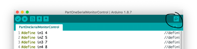
Primeira etapa:Faça upload de um programa vazio para a placa Arduino
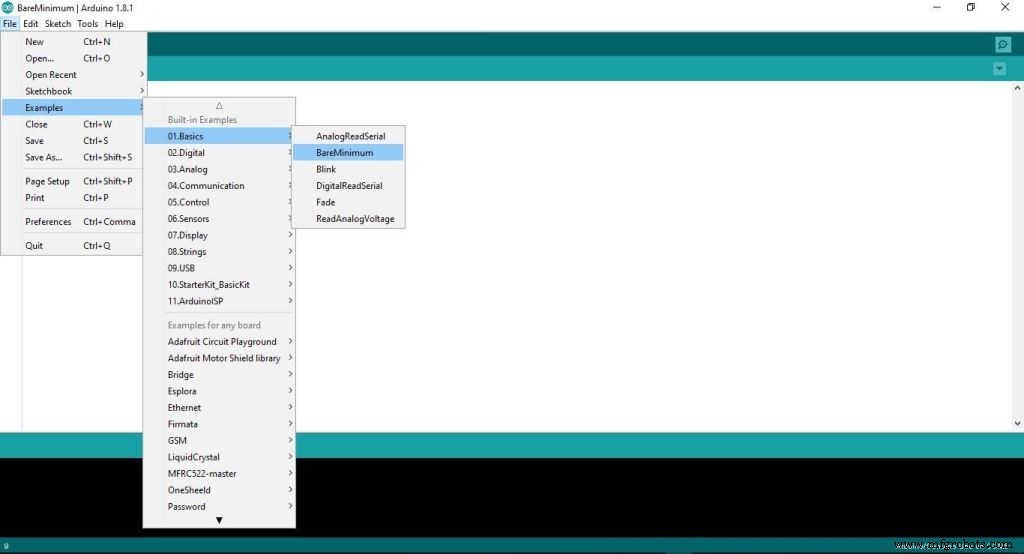
Nesta etapa, estamos carregando um código vazio para a placa Arduino. Apenas para ter certeza de que não há nada sendo executado em segundo plano pela placa Arduino.
Segunda etapa:conectar o ESP8266-01 com a placa Arduino
Para reconfigurar o ESP8266-01 e alterar a velocidade de comunicação (taxa de transmissão), usamos os comandos AT. Simplesmente, os comandos AT são algumas instruções usadas para controlar modems, telefones celulares, módulos Bluetooth, módulos wi-fi, Módulos GSM.
com esses comandos, podemos obter informações básicas sobre nosso telefone celular ou Módulos GSM, como o nome do fabricante, número do modelo, IMEI e assim por diante. “AT” é uma abreviatura para “ATtention” e é chamado de comandos AT porque cada comando é iniciado com a". o prefixo “AT” não faz parte dos comandos em si, apenas informa ao módulo o início dos comandos.
Alguns comandos AT importantes
Número do comando “4” depende da versão do firmware do ESP8266-01, se este comando não funcionar com você
AT + CIOBAUD = Tente este AT + UART_DEF =, 8,1,0,0 Etapa 1:Abra o Monitor Serial
Etapa 2:defina a velocidade de comunicação para 115, 200 baud

Como dissemos antes, o ESP vem do fabricante programado para se comunicar na velocidade de 115, 200 baud. Portanto, precisamos definir a velocidade de comunicação do Arduino para 115, 200 também pela primeira vez, só então vamos mudar isso mais tarde. Além disso, você deve selecionar “Ambos NL e CR” .
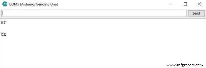
Etapa 3:envie “AT” e aguarde a resposta para ter certeza de que o módulo ESP está ouvindo você.
Etapa 4:agora, altere a velocidade de comunicação ESP8266-01
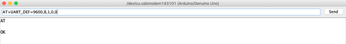
Meu firmware carregado com o módulo ESP8266-01 é 1.6. e este comando
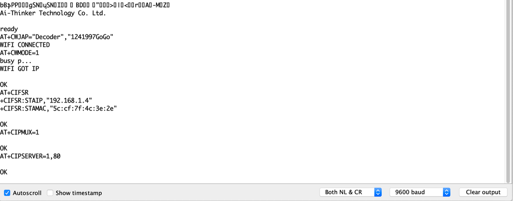
AT + UART_DEF =, 8,1,0,0 funciona bem para mim. Se não funcionar com você, tente este AT + CIOBAUD = . Se responder com “OK” agora a taxa de transmissão de comunicação do módulo ESP mudou de 115, 200 baud para 9600 baud. PARABÉNS! 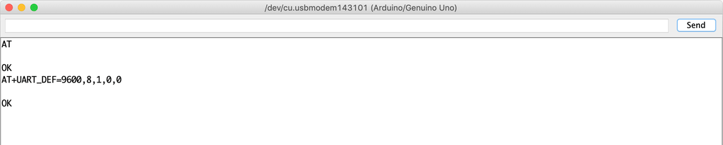
Vamos mudar a velocidade de comunicação do monitor serial de volta para 9600 e enviar "AT" novamente para ver se o módulo ESP pode nos ouvir na nova velocidade (9600) ou não.
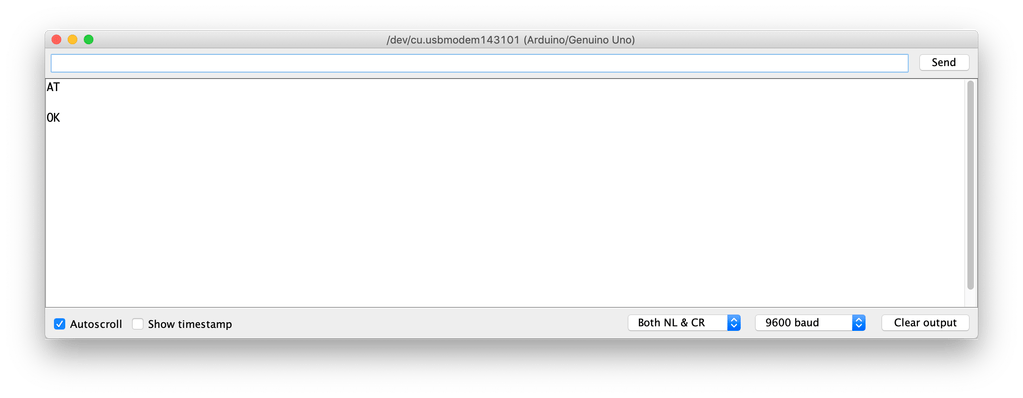
VEJA! está funcionando. o ESP8266-01 agora pode se comunicar com a placa Arduino a uma taxa de 9600 bauds em vez de 115,200 bauds.
Agora, vamos tentar se conectar à rede Wifi
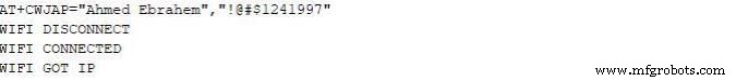
Assim que você pressionar Enter, o ESP8266-01 pesquisará essa rede e se conectará a ela. Se o processo for bem-sucedido, ele retornará este
WIFI CONECTADO WIFI GOT IP Nesse ponto, alteramos com sucesso a velocidade de comunicação do ESP8266-01 de 115, 200 baud para 9600 baud. Agora, precisamos construir o painel de controle (Web Page) que o usuário utilizará para controlar seus eletrodomésticos. Então, vamos construir!
O que é a Internet?
Na verdade, a internet é um fio enterrado sob o solo, pode ser fibra ótica, cobre ou mesmo um satélite, mas a internet é simplesmente um fio. Qualquer dois computadores conectados a esse fio podem se comunicar. Se o computador estiver conectado diretamente a esse fio é chamado de servidor e se não estiver conectado diretamente a esse fio, é chamado de cliente .
Servidor: é um computador especial que executa um sistema operacional específico como o Apache, este computador especial salva algumas páginas da web, arquivos, bancos de dados em sua unidade de disco. qualquer servidor conectado à internet tem um endereço IP exclusivo como 172.217.171.228 , o endereço IP é como um número de telefone que ajuda as pessoas a se encontrarem facilmente. Uma vez que esse endereço IP não é muito fácil de ser lembrado por humanos. Então, acabamos de dar a ele um nome de google.com (Nome do domínio).
Cliente: é um computador como o que você e eu usamos todos os dias, ele está conectado indiretamente à internet por meio de um provedor de serviços de internet (ISP) e também tem um endereço IP exclusivo.
Cenário de trabalho
Simplesmente, começa com uma solicitação enviada de um navegador da web (Cliente) como o google chrome, firefox e termina com a resposta recebida do servidor da web.
Você inseriu o URL do site makesomestuff.org em um navegador de um computador (cliente), então este navegador envia uma solicitação para o servidor web hospeda o site, o servidor web então retorna uma resposta contém página HTML ou qualquer outro formato de documento para o navegador exibir isto.
Exatamente, é isso que precisamos fazer hoje em nosso projeto. Precisamos enviar um pedido do navegador web (Cliente) para o ESP8266-01 (servidor web) em que ambos estão conectados na mesma rede local. Essa solicitação contém alguns dados que informam ao Arduino o que fazer, ligando ou desligando uma lâmpada. Então, vamos construir a página da web!
Construindo a página da web
Para construir nossa página web, temos que lidar com HTML, CSS, Javascript. Se você nunca ouviu falar desses nomes antes, não se preocupe, peguei você.
HTML: Significa “linguagem de marcação de hipertexto” que usamos para construir a estrutura principal de qualquer página da web. Como adicionar alguns botões, imagens, parágrafos, cabeçalhos, tabelas e muitos outros elementos. ele consiste em uma série de elementos que informam ao navegador como exibir o conteúdo da página da web. esses elementos são representados por algo chamado tags.

CSS: Significa folha de estilo em cascata. Depois de construir a estrutura principal da página da web, você precisa fazer com que essa estrutura pareça boa, aqui vem o CSS para fazer alguns estilos. é uma linguagem que descreve o estilo de um elemento HTML. consiste em alguns seletores e blocos de desaceleração.

Javascript: é uma linguagem de programação que usaremos para tornar a página da web mais interativa, como adicionar algumas animações, mapas e nos permite fazer algumas coisas complexas na página da web. Principalmente, vamos usá-lo hoje para enviar uma solicitação HTTP do cliente (navegador da web) para o servidor da web (ESP8266-01) para realizar algumas ações como ligar ou desligar uma lâmpada.

Construir a estrutura da página da web
Para entender facilmente a próxima explicação, eu recomendo Ler isto legal introdução de HTML .
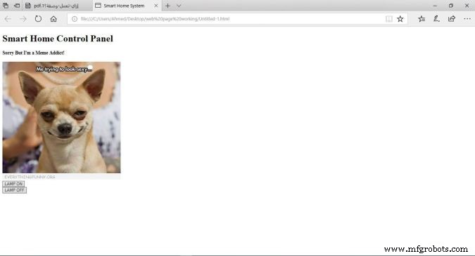
Como podemos ver nosso painel de controle é muito simples, ele contém dois cabeçalhos cada um com um tamanho diferente, uma imagem e dois botões um para ligar um LED e outro para desligá-lo.
Código
Sistema de casa inteligente Painel de controle de casa inteligente
Desculpe, mas Sou viciado em meme!

Explicação do código
- : declaração define que este documento é um documento HMTL5.
- : o elemento raiz de uma página HTML.
- : elemento contém metainformações sobre a página.
-
:</strong> elemento especifica o título do documento. este título aparece na guia do navegador da página da web. </li> <li> <strong> <body>:</strong> elemento contém o conteúdo visível da página da web. </li> <li> <strong> <h1>:</strong> elemento define um grande elemento. </li> <li> <strong> <h4>:</strong> elemento define um cabeçalho menor. quando o valor do cabeçalho diminui, a fonte diminui. </li> <li> <strong> <img>:</strong> elemento adiciona uma imagem à página da web. a imagem que você deseja exibir deve estar na mesma pasta do projeto. </li> <li> <strong> <br>:</strong> avance o cursor para uma nova linha. </li> <li> <strong> <button>:</strong> elemento adiciona um botão ao conteúdo da página. </li> </ul> <br> Cada botão da nossa página web tem dois atributos muito importantes, o <code> id </code> , e a <code> classe </code> atributos. falaremos sobre por que atribuímos esses dois valores aos botões na explicação do código Jquery. <br> <h3 id ='toc-styling-the-web-page-12'> <br> <br> <br> <br> Estilizando a página da web </h3> <br> <strong> <em> Para entender facilmente a próxima explicação, eu recomendo Ler isto legal </em> </strong> <strong> <em> Introdução de CSS </em> </strong> <strong> <em>. </em> </strong> <br> <img loading='lazy' src ="https://www.mfgrobots.com/article/uploadfiles/202112/2021122812180042.jpg?auto=compress%2Cformat&w=680&h=510&fit=max" /> </figure> <br> Agora, a página da web parece melhor (NÃO MUITO xD), demos a ela uma cor de fundo verde legal, alinhamos o conteúdo da página ao centro e mudamos a cor da fonte dos cabeçalhos e a família da fonte, o que tornou a página da web mais viva. Usamos CSS para fazer todas essas coisas de estilo. <br> <br> <strong> Código </strong> <br> <pre> <code> <! DOCTYPE html> <html> <head> <title> Sistema de casa inteligente Painel de controle de casa inteligente
Desculpe, mas sou viciado em meme!

LAMP ON
Explicação do código
Adicionamos algumas linhas de código para tornar nossa página da web mais agradável. Adicionamosstyle ="background-color:seagreen; color:seashell; text-align:center;"dentro do corpo tag para tornar todo o conteúdo da página da web no centro da página e para definir a cor de fundo para verde marinho também para definir a cor da fonte para concha .
Além disso, adicionamosstyle ="margin:10px;"dentro das duas tags de botão para definir uma margem de 10 pixels ao redor dos quatro lados de cada botão.
Enviando uma solicitação para o servidor da Web
Para entender facilmente a próxima explicação, eu recomendo Ler isto legal introdução do Jquery .
Agora, depois de construir nossa estrutura de página da web e estilizá-la, precisamos adicionar alguma funcionalidade aos dois botões que adicionamos anteriormente na página da web. precisamos que, quando o usuário clicar no botão “LAMP ON”, seu navegador envie uma solicitação contendo alguns dados exclusivos para o servidor (ESP8266-01), esses dados exclusivos digam ao Arduino para ligar a lâmpada. A mesma coisa com o segundo botão “LAMP OFF” quando o usuário clica nele, o navegador enviará uma solicitação contendo alguns dados exclusivos para o servidor (ESP8266-01). Esses dados exclusivos dizem ao Arduino para desligar a lâmpada. Vamos dar uma olhada no código.
Sistema de casa inteligente Painel de controle de casa inteligente
Desculpe, mas sou viciado em meme!
Explicação do código
Primeiras coisas Primeiro, precisamos importar a biblioteca Jquery em nosso código. Então, adicionamos esta linha na tag head .
Toda a magia acontece nesta parte interessante.
-
$ (".botão"). click (função () {
Quando o usuário clica em qualquer botão associado à classe “botão” , acione a seguinte função.
-
var p =$ (this) .attr ('id');
Obtenha o valor do atributo do botão clicado “id” e armazene-o dentro do “p” variável.
-
pin:p
Coloque o valor da variável “p” em um dicionário (valor-chave), sua chave é “pin” e o valor é o valor da variável “p”.
-
$ .get ("http://172.20.10.11:80/", {pin:p});});
Em seguida, envie uma solicitação GET para o servidor web cujo endereço IP é “172.20.10.11”. este GET solicitação contém o valor do atributo id botão pressionado.
Caso o usuário tenha pressionado o botão “LAMP ON”, este valor de id será 111, então o cabeçalho da solicitação GET conterá alguns dados como este pin =111 . olhe para a próxima figura!
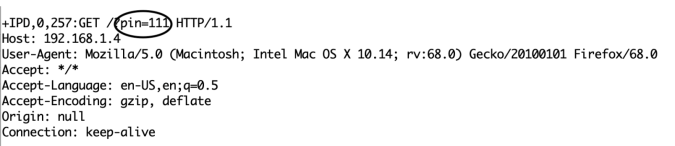
No lado oposto, se o usuário pressionou o botão “LÂMPADA DESLIGADA”, a solicitação conterá esses dados pin =110 .
Code Logic
Eu sei que você está perguntando agora por que diabos ele escolheu 111 e 110 especificamente? Ok, deixe-me responder a você fam. Na verdade, o número 111 e 110 divide-se em duas partes.
- Parte um: são os primeiros dois números, que em ambos os casos serão “11”, refere-se ao número do pino do Arduino ao qual a carga que preciso controlar está conectada.
- Parte dois: é o terceiro número que muda entre 1 e 0 dependendo do botão clicado. E se refere ao estado do pino (LIGADO ou DESLIGADO).
No código do Arduino, receberemos esses dados e separaremos essas duas partes uma da outra e salvaremos cada parte em uma variável diferente, a parte um na variávelpinNumbere a segunda parte na variávelpinState, então escreveremos esta linha simples de código para controlar a carga conectadadigitalWrite (pinNumber, pinState);
Conectando a carga
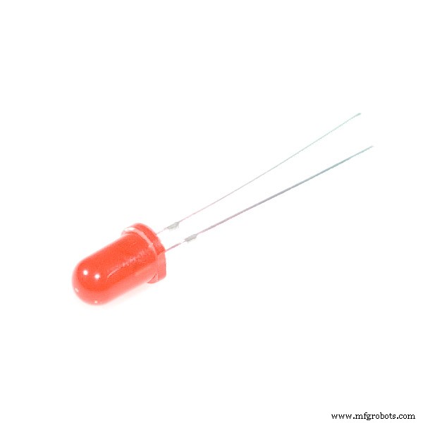
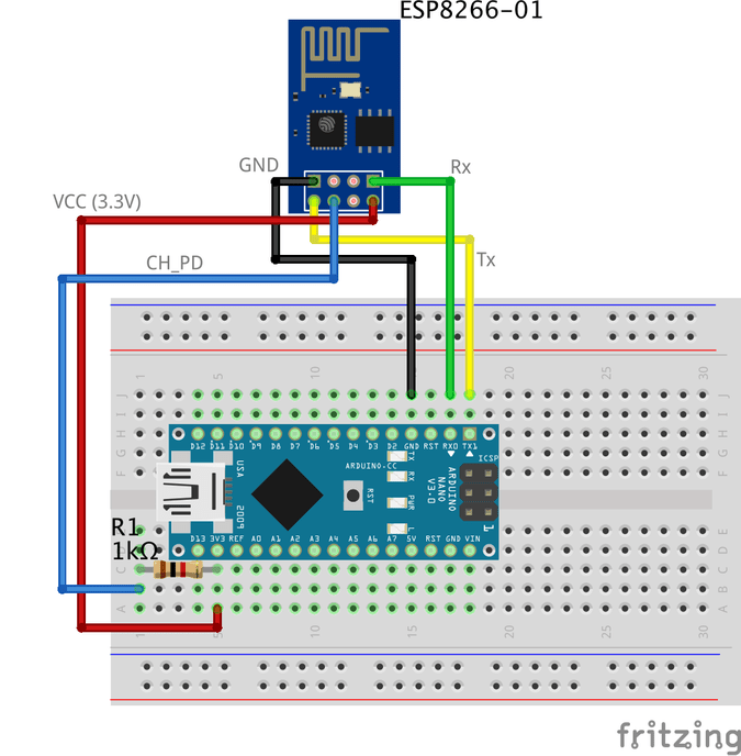
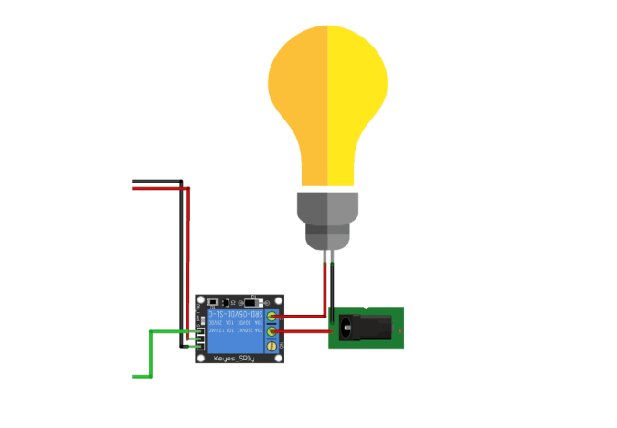
Agora, precisamos conectar a carga com a placa Arduino para controlá-la. Antes de conectar qualquer dispositivo de alta tensão como o ar condicionado ou até mesmo a TV, precisamos testar nosso circuito e o código com algumas coisas de baixa tensão como LEDs apenas para ter certeza de que tudo está funcionando bem. Aqui está o diagrama de fiação
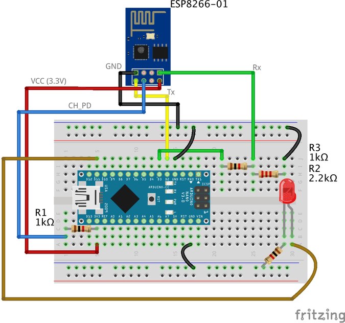
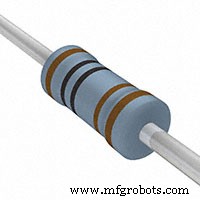
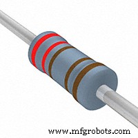
A fiação é bem simples, estamos conectando a perna positiva do LED ao pino digital 11 do Arduino e a perna negativa ao GND por meio de um resistor de 1k ohm.
Código Arduino
#include// incluindo a biblioteca SoftwareSerial permitirá que você use o número do pin. 2,3 como Rx, Tx. SoftwareSerial esp8266 (2,3); // defina o Rx ==> Pino 2; TX ==> Pin3. #define serialCommunicationSpeed 9600 // <=========define uma constante chamada "serialCommunicationSpeed" com um valor 9600. refere-se à velocidade de comunicação serial do software e do hardware (taxa de transmissão). #define DEBUG true // cria uma constante chamada "DEBUG" e seu valor é true. vamos usá-lo mais tarde. int redLED =12; // atribui uma variável chamada "redLED" com um valor inteiro 12, refere-se ao pino ao qual o LED vermelho está conectado. int azulLED =11; // atribui uma variável chamada "blueLED" com um valor inteiro 11, refere-se ao pino ao qual o LED azul está conectado. void setup () {pinMode (redLED, OUTPUT); // define o pino número 12 como um pino de saída. pinMode (blueLED, OUTPUT); // define o pino número 11 como um pino de saída. digitalWrite (redLED, LOW); // desligue o LED vermelho no início do programa. digitalWrite (blueLED, HIGH); // liga o LED azul no início do programa. Serial.begin (serialCommunicationSpeed); // inicia a comunicação serial do Hardware (0, 1) na velocidade 9600. esp8266.begin (serialCommunicationSpeed); // inicia a comunicação serial do software (2, 3) na velocidade 9600. InitWifiModule (); // chame esta função definida pelo usuário "InitWifiModule ()" para inicializar uma comunicação entre o ESP8266 e seu ponto de acesso (roteador doméstico ou mesmo seu hotspot móvel). digitalWrite (blueLED, LOW); // após terminar a inicialização com sucesso, desligue o LED azul (apenas um indicador). } void loop () // nosso programa principal, alguma diversão está prestes a começar) {if (esp8266.available ()) // se houver algum dado recebido e armazenado no buffer de recepção serial, vá e execute o corpo da condição if . Do contrário, não execute o corpo da condição se de forma alguma. {if (esp8266.find ("+ IPD,")) // pesquisar a string "+ IPD," nos dados de entrada. if it exists the ".find()" returns true and if not it returns false. { delay(1000); //wait 1 second to fill up the buffer with the data. int connectionId =esp8266.read()-48; //Subtract 48 because the read() function returns the ASCII decimal value. And 0 (the first decimal number) starts at 48. We use it to convert from ASCI decimal value to a character value. esp8266.find("pin="); //Advance the cursor to the "pin=" part in the request header to read the incoming bytes after the "pin=" part which is the pinNumer and it's state. int pinNumber =(esp8266.read()-48)*10; //read the first Byte from the Arduino input buffer(i.e. if the pin 12 then the 1st number is 1) then multiply this number by 10. So, the final value of the "pinNumber" variable will be 10. pinNumber =pinNumber + (esp8266.read()-48); //read the second Byte from the Arduino input buffer(i.e. if the pin number is 12 then the 2nd number is 2) then add this number to the first number. So, the final value of the "pinNumber" variable will be 12. int statusLed =(esp8266.read()-48); //read the third byte from the Arduino input buffer. then save it inside the "statusLed" variable. At any case, it will be 1 or 0. digitalWrite(pinNumber, statusLed); //then turn the LED at "pinNumber" on or off depending on the "statusLed" variable value. Serial.println(connectionId); //print the "connectionId" value on the serial monitor for debugging purposes. Serial.print(pinNumber); //print the "pinNumber" value on the serial monitor for debugging purposes. Serial.print (""); //print some spaces on the serial monitor to make it more readable. Serial.println(statusLed); //print the "statusLed" value on the serial monitor for debugging purposes. String closeCommand ="AT+CIPCLOSE="; //close the TCP/IP connection. closeCommand+=connectionId; //append the "connectionId" value to the string. closeCommand+="\r\n"; //append the "\r\n" to the string. it simulates the keyboard enter press. sendData(closeCommand,1000,DEBUG); //then send this command to the ESP8266 module to excute it. } } } /****************************************************************************************************************************************************************************************** * Name:sendData * Description:this Function regulates how the AT Commands will ge sent to the ESP8266. * * Params:command - the AT Command to send * - timeout - the time to wait for a response * - debug - print to Serial window?(true =yes, false =no) * * Returns:The response from the esp8266 (if there is a reponse) */ String sendData(String command, const int timeout, boolean debug) { String response =""; //initialize a String variable named "response". we will use it later. esp8266.print (comando); //send the AT command to the esp8266 (from ARDUINO to ESP8266). tempo interno longo =milis (); //get the operating time at this specific moment and save it inside the "time" variable. while( (time+timeout)> millis()) //excute only whitin 1 second. { while(esp8266.available()) //is there any response came from the ESP8266 and saved in the Arduino input buffer? { char c =esp8266.read(); //if yes, read the next character from the input buffer and save it in the "response" String variable. response+=c; //append the next character to the response variabl. at the end we will get a string(array of characters) contains the response. } } if(debug) //if the "debug" variable value is TRUE, print the response on the Serial monitor. { Serial.print(response); } return response; //return the String response. } /****************************************************************************************************************************************************************************************** * Name:InitWifiModule * Description:this Function gives the commands that we need to send to the sendData() function to send it. * * Params:Nothing. * * Returns:Nothing (void). */ void InitWifiModule() { sendData("AT+RST\r\n", 2000, DEBUG); //reset the ESP8266 module. //delay(1000); sendData("AT+CWJAP=\"PUT YOUR SSID\",\"PUT YOUR PASSWORD\"\r\n", 2000, DEBUG); //connect to the WiFi network. delay (3000); sendData("AT+CWMODE=1\r\n", 1500, DEBUG); //set the ESP8266 WiFi mode to station mode. atraso (1000); sendData("AT+CIFSR\r\n", 1500, DEBUG); //Show IP Address, and the MAC Address. atraso (1000); sendData("AT+CIPMUX=1\r\n", 1500, DEBUG); //Multiple conections. atraso (1000); sendData("AT+CIPSERVER=1,80\r\n", 1500, DEBUG); //start the communication at port 80, port 80 used to communicate with the web servers through the http requests. }
code explanation
the code is pretty straightforward, we implemented two different functionsInitWifiModule()andsendData()
ThesendData()function job is regulating how the AT commands will get sent to the ESP8266-01 module.
theInitWifiModule()function job is to provide thesendData()function the AT commands that we need to send to the ESP8266-01.
in theloop()function we read the income HTTP request header and search for the “+IPD, ” which means that the request has successfully arrived, then we read the pin value which it will be “111” if the user clicked the “LAMP ON” button and “110” if the user clicked “LAMP OFF” button.
Don’t forget to put your wifi SSID and Password in the Arduino code line no. 103sendData("AT+CWJAP=\"PUT YOUR SSID\",\"PUT YOUR PASSWORD\"\r\n", 2000, DEBUG);
For more code explanation please read the comments in the code, it’s well documented
Como funciona
After uploading the code to the Arduino board, open the Serial monitor and read the responses that the ESP module is sending.
at the beginning of the program, if you see something like the previous figure with “OK” at the end of the page, it means that the ESP8266-01 module is successfully connected to your wifi (Access point) and got an IP and MAC address. Now, you can open your fancy web page and try to control some stuff 😉
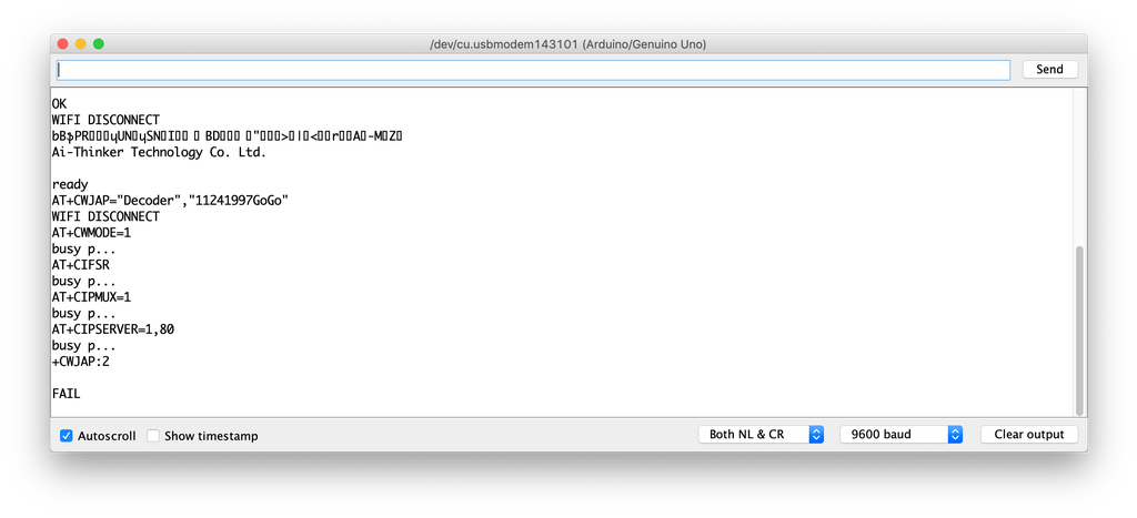
But, if you see something like the previous figure with a “FAIL” or “ERROR” at the end of the page, it means that your ESP module cant connect to your wifi (Access point) for some reasons, try to check if entered the right SSID and password for your network.
Adding a High Voltage Load
After we tested our code and got sure that everything is working like a charm, we need to replace this boring LED with a High voltage load like an air conditioner, TV or a light bulb. But to control all of these high voltage appliances we have to deal with relays .
What’s and why relays? Ok, the relay is a mechanical switch, which is toggled on or off by energizing a coil. it’s mainly used to control a high powered circuit using a low power signal (5V or 0V). So we can control a high powered device like an air conditioner or an AC lamp turning it on or off only by a 5V or 0V signal. Which is amazing!
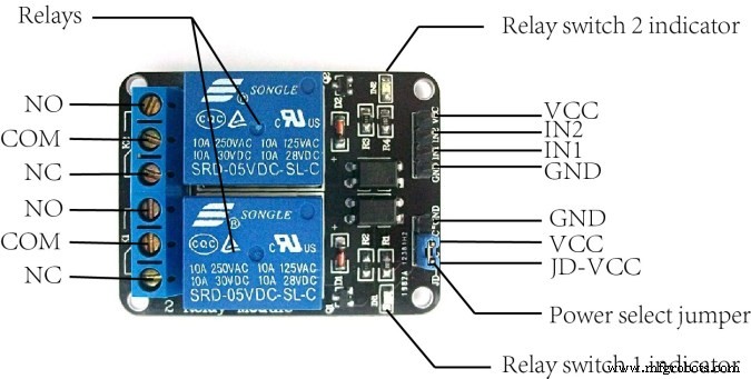
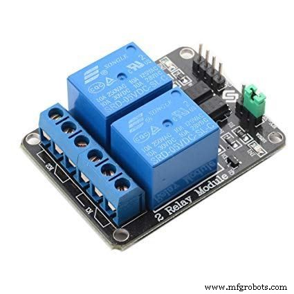
The Two-channel relay module has two control pins(IN1, IN2) these pins should get connected to two Arduino digital pins to control the state of the two coils, closes or opens the load circuit.
At the opposite side of the relay module, the COM(common) should get connected to one end of the load. the other end of the load is either connected to the NC(Normally Close) or NO(Normally open) , if connected to the NO the load remains Disconnected before trigger and vice versa.
Wiring Diagram
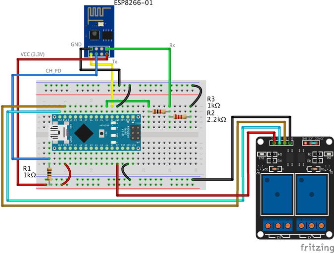
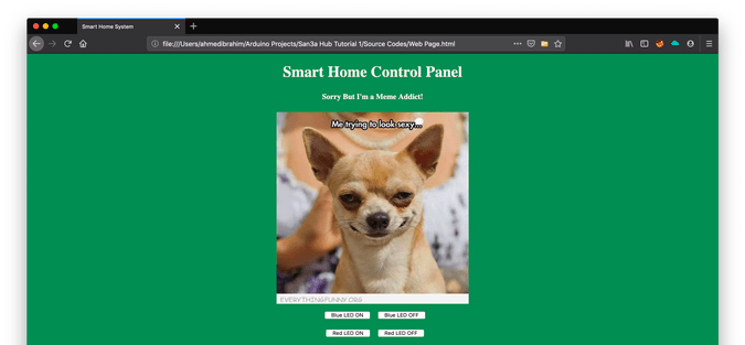
As you see, we are using a two-channel relay module that gives us the ability to control two different AC loads. We are connecting the first relay at digital output pin11(Arduino) and the second relay to digital output pin 12(Arduino)
We will make a small modification to our web page, we will add another two buttons(ON and OFF) to control the second connected load.
Smart Home System Smart Home Control Panel
Sorry But I'm a Meme Addict!
How It Works
Just like the last trial, You upload the Arduino code to the board (if not uploaded yet) and open the serial monitor and make sure that your ESP module is connected successfully to your access point and got an IP and MAC address.
Then open your fancy web page and start controlling your stuff 😉
Make it more professional!
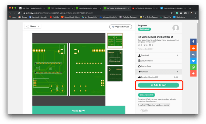
What about transferring our breadboard circuit to a professional printed circuit board (PCB) to make our project more rigid and solid, I designed the project circuit using Autodesk Eagle software. all the PCB files are open-source you can access it from this link:https://www.pcbway.com/project/shareproject/IoT_Using_Arduino_and_ESP8266_01.html
Because we love open source 😉
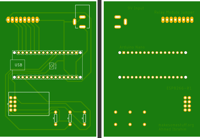
You can order your own PCB From PCBWay company these guys have a very good reputation in this field and they ship to more than 170 countries around the world with reasonable prices. all you have to do is to open the project PCB files link and press “Add to cart”. That’s it!
Solução de problemas
if your ESP Module is successfully connected to your access point but there is no action happens when you click the web page buttons
- make sure that you are sending the request from your web browser from port 80(HTTP). example:
$.get("http://192.168.1.4:80/"
- make sure that your PC or Laptop and the ESP module is connected to the same Access point.
- In Jquery code, make sure that you wrote the right ESP module IP address.
- Make sure that you are connecting the load at Arduino digital pins 11 and 12.
- Don’t forget to save the Web page code file after any change or modification, and reload the web page in the web browser after any code modification to take effect.
Final
We are done! in today’s tutorial, we learned how to build a simple web page using HTML, CSS, and jquery. Also, we learned how to control an AC load wirelessly from a web-based control panel, and how to use the awesome ESP8266-01 Wifi module with the Arduino board.
you wanna see more Tutorials and open source projects you can also visit my blog www.makesomestuff.org
Lastly, if you have any questions drop it in the comments section below, I will be more than happy to hear from you 😉
-
Código
- Web Page
- Final Arduino Code
Web PageHTML
Smart Home System Smart Home Control Panel
Sorry But I'm a Meme Addict!
Final Arduino CodeArduino
#include//including the SoftwareSerial library will allow you to use the pin no. 2,3 as Rx, Tx.SoftwareSerial esp8266(2,3); //set the Rx ==> Pin 2; TX ==> Pin3.#define serialCommunicationSpeed 9600 // <=========define a constant named "serialCommunicationSpeed" with a value 9600. it referes to the Software and hardware serial communication speed(baud rate).#define DEBUG true //make a constant named "DEBUG" and it's value true. we will use it later.int redLED =12; //assign a variable named "redLED" with an integer value 12, it refers to the pin which the red LED is connected on.int blueLED =11; //assign a variable named "blueLED" with an integer value 11, it refers to the pin which the blue LED is connected on.void setup(){ pinMode(redLED,OUTPUT); //set the pin number 12 as an output pin. pinMode(blueLED,OUTPUT); //set the pin number 11 as an output pin. digitalWrite(redLED,LOW); //turn the red LED off at the beginning of the program. digitalWrite(blueLED,HIGH); //turn the blue LED on at the beginning of the program. Serial.begin(serialCommunicationSpeed); //begin the Hardware serial communication (0, 1) at speed 9600. esp8266.begin(serialCommunicationSpeed); //begin the software serial communication (2, 3) at speed 9600. InitWifiModule(); //call this user-defined function "InitWifiModule()" to initialize a communication between the ESP8266 and your access point (Home Router or even your mobile hotspot). digitalWrite(blueLED,LOW); //after finishing the initialization successfully, turn off the blue LED (just an indicator).}void loop() //our main program, some fun are about to start){ if(esp8266.available()) //if there's any data received and stored in the serial receive buffer, go and excute the if-condition body. If not, dont excute the if-condition body at all. { if(esp8266.find("+IPD,")) //search for the "+IPD," string in the incoming data. if it exists the ".find()" returns true and if not it returns false. { delay(1000); //wait 1 second to fill up the buffer with the data. int connectionId =esp8266.read()-48; //Subtract 48 because the read() function returns the ASCII decimal value. And 0 (the first decimal number) starts at 48. We use it to convert from ASCI decimal value to a character value. esp8266.find("pin="); //Advance the cursor to the "pin=" part in the request header to read the incoming bytes after the "pin=" part which is the pinNumer and it's state. int pinNumber =(esp8266.read()-48)*10; //read the first Byte from the Arduino input buffer(i.e. if the pin 12 then the 1st number is 1) then multiply this number by 10. So, the final value of the "pinNumber" variable will be 10. pinNumber =pinNumber + (esp8266.read()-48); //read the second Byte from the Arduino input buffer(i.e. if the pin number is 12 then the 2nd number is 2) then add this number to the first number. So, the final value of the "pinNumber" variable will be 12. int statusLed =(esp8266.read()-48); //read the third byte from the Arduino input buffer. then save it inside the "statusLed" variable. At any case, it will be 1 or 0. digitalWrite(pinNumber, statusLed); //then turn the LED at "pinNumber" on or off depending on the "statusLed" variable value. Serial.println(connectionId); //print the "connectionId" value on the serial monitor for debugging purposes. Serial.print(pinNumber); //print the "pinNumber" value on the serial monitor for debugging purposes. Serial.print (""); //print some spaces on the serial monitor to make it more readable. Serial.println(statusLed); //print the "statusLed" value on the serial monitor for debugging purposes. String closeCommand ="AT+CIPCLOSE="; //close the TCP/IP connection. closeCommand+=connectionId; //append the "connectionId" value to the string. closeCommand+="\r\n"; //append the "\r\n" to the string. it simulates the keyboard enter press. sendData(closeCommand,1000,DEBUG); //then send this command to the ESP8266 module to excute it. } }}/******************************************************************************************************************************************************************************************* Name:sendData* Description:this Function regulates how the AT Commands will ge sent to the ESP8266.* * Params:command - the AT Command to send * - timeout - the time to wait for a response * - debug - print to Serial window?(true =yes, false =no)* * Returns:The response from the esp8266 (if there is a reponse)*/String sendData(String command, const int timeout, boolean debug){ String response =""; //initialize a String variable named "response". we will use it later. esp8266.print (comando); //send the AT command to the esp8266 (from ARDUINO to ESP8266). tempo interno longo =milis (); //get the operating time at this specific moment and save it inside the "time" variable. while( (time+timeout)> millis()) //excute only whitin 1 second. { while(esp8266.available()) //is there any response came from the ESP8266 and saved in the Arduino input buffer? { char c =esp8266.read(); //if yes, read the next character from the input buffer and save it in the "response" String variable. response+=c; //append the next character to the response variabl. at the end we will get a string(array of characters) contains the response. } } if(debug) //if the "debug" variable value is TRUE, print the response on the Serial monitor. { Serial.print(response); } return response; //return the String response.}/******************************************************************************************************************************************************************************************* Name:InitWifiModule* Description:this Function gives the commands that we need to send to the sendData() function to send it.* * Params:Nothing.* * Returns:Nothing (void).*/void InitWifiModule(){ sendData("AT+RST\r\n", 2000, DEBUG); //reset the ESP8266 module. //delay(1000); sendData("AT+CWJAP=\"Decoder\",\"1241997GoGo\"\r\n", 2000, DEBUG); //connect to the WiFi network. delay (3000); sendData("AT+CWMODE=1\r\n", 1500, DEBUG); //set the ESP8266 WiFi mode to station mode. delay (1500); sendData("AT+CIFSR\r\n", 1500, DEBUG); //Show IP Address, and the MAC Address. delay (1500); sendData("AT+CIPMUX=1\r\n", 1500, DEBUG); //Multiple conections. delay (1500); sendData("AT+CIPSERVER=1,80\r\n", 1500, DEBUG); //start the communication at port 80, port 80 used to communicate with the web servers through the http requests.}
Esquemas
Processo de manufatura
- Detector de linguagem TinyML baseado em Edge Impulse e Arduino
- Jogo Arduino Gyroscope com MPU-6050
- Dados digitais Arduino
- Máquina de LEVITAÇÃO ULTRASÔNICA Usando ARDUINO
- Faça você mesmo voltímetro usando Arduino e Smartphone
- Monitor de freqüência cardíaca usando IoT
- IOT - Jar inteligente usando ESP8266, Arduino e sensor ultrassônico
- Sonar usando arduino e exibição no IDE de processamento
- Controle de brilho do LED usando Bolt e Arduino
- Controle total de sua TV usando Alexa e Arduino IoT Cloud