


Princípios Metalúrgicos no Tratamento Térmico de Aços
Princípios metalúrgicos no tratamento térmico de aços
O tratamento térmico dos aços é realizado para alcançar as mudanças desejadas nas propriedades da estrutura metalúrgica dos aços. Por tratamento térmico, os aços sofrem intensas alterações nas propriedades. Normalmente, estruturas de aço muito estáveis são obtidas quando o aço é aquecido ao estado austenítico de alta temperatura e depois resfriado lentamente em condições próximas do equilíbrio. Este tipo de tratamento térmico, normalmente conhecido como recozimento ou normalização, produz uma estrutura com baixo nível de tensões residuais bloqueadas dentro do aço, e as estruturas podem ser previstas a partir do diagrama de equilíbrio Fe (ferro)-C (carbono). No entanto, as propriedades mais exigidas nos aços são alta resistência e dureza e geralmente são acompanhadas por altos níveis de tensões residuais. Estes são devidos às estruturas metaestáveis produzidas pelo resfriamento fora do equilíbrio ou têmpera do estado austenítico.
Estrutura e fases de cristal
A estrutura cristalina do Fe puro no estado sólido é conhecida por existir em dois estados alotróficos. A partir da temperatura ambiente e até 910°C, o Fe possui uma rede cúbica de corpo centrado (bcc) e é chamado de alfa-Fe. A 910°C, os cristais de alfa-Fe se transformam em cristais de gama-Fe possuindo uma rede cúbica de face centrada (fcc). Os cristais gama mantêm a estabilidade até a temperatura de 1400 graus C. Acima dessa temperatura eles novamente adquirem uma rede bcc que é conhecida como cristais delta. Os cristais delta diferem dos cristais alfa apenas na região de temperatura de sua existência. Fe tem duas constantes de rede a saber (i) 0,286 nm para redes bcc (alfa-Fe, delta-Fe) e (ii) 0,364 nm para redes fcc (gama-Fe). Em baixas temperaturas, o alfa-Fe apresenta forte característica ferromagnética. Isso desaparece quando é aquecido a cerca de 770 graus C, uma vez que a rede perde seu ordenamento de spin ferromagnético. O estado de Fe acima de 770 graus C é chamado beta-Fe. A rede dos cristais beta paramagnéticos é idêntica à rede dos cristais alfa.
Ao passar de uma forma para outra, o Fe é capaz de subresfriar. Isso causa uma diferença na posição dos pontos de transformação no aquecimento e resfriamento. A diferença depende da taxa de resfriamento e é chamada de histerese. As letras ‘c’ e ‘r’ indicam se a transformação é devido ao aquecimento ou resfriamento. Além disso, a mudança na densidade do alfa-Fe à medida que se transforma em gama-Fe resulta em uma mudança abrupta no volume do material. Às vezes, dá origem a tensões que excedem o limite elástico e levam à falha. A densidade do gama-Fe é cerca de 4% maior do que a do alfa-Fe.
Diagrama de equilíbrio ferro-carbono
A estrutura dos aços, que são ligas Fe-C, pode conter C puro (grafite) ou um composto químico conhecido como cementita (Fe3C) como constituinte enriquecido com C. A cementita está presente mesmo em aços resfriados de forma relativamente lenta (geralmente é necessária uma longa permanência em temperaturas mais altas para decompor Fe3C em Fe e C). Por esta razão, o diagrama de equilíbrio Fe-C é frequentemente tratado como o diagrama de equilíbrio Fe-Fe3C. O diagrama Fe-C é estável, enquanto o diagrama Fe-Fe3C é metaestável. O diagrama de equilíbrio Fe-C incorporando tanto o diagrama estável Fe-C quanto o diagrama metaestável Fe-Fe3C é dado na Figura 1. As linhas tracejadas representam o diagrama Fe-C estável e as linhas sólidas indicam o diagrama Fe-Fe3C metaestável.
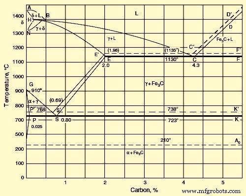
Fig 1 Diagrama de carbono do ferro
No diagrama metaestável Fe-Fe3C, as redes de formas alotrópicas de Fe (delta, gama e alfa) servem como locais de formação de delta, gama e soluções sólidas de C em Fe. Quando aços sem C cristalizam, cristais da solução sólida delta precipitam no liquidus AB e solidus AH. A solução sólida delta tem uma rede bcc. Na temperatura máxima de 1490 graus C, a solução delta contém 0,1% C (ponto H). A 1490°C, ocorre uma reação peritética entre a solução saturada delta e o líquido contendo 0,5% C (ponto B). Como resultado, a solução sólida gama de C em gama Fe é formada. Contém 0,18% C (ponto I).
Se o teor de C for superior a 0,5%, a solução sólida gama cristaliza diretamente do líquido (no liquidus BC e solidus IE). A 1130 graus C, a solubilidade limitante de C em gama Fe é próxima de 2,0% (ponto E). Diminuir a temperatura de 1130 graus C leva a diminuir a solubilidade C em gama-Fe na linha ES. A 723 graus C a solubilidade de C é de 0,8% (ponto S). A linha ES corresponde à precipitação de Fe3C da solução gama.
À medida que o teor de C aumenta, a temperatura na qual a rede gama se transforma na rede alfa diminui, e a transformação ocorre ao longo do intervalo de temperatura correspondente às curvas GS e GP. A curva de precipitação de fase alfa GS intercepta a curva de precipitação de Fe3C ES. O ponto S é um ponto eutetóide com as coordenadas 723 graus C e 0,80 % C. Neste ponto, uma solução alfa saturada e precipitado de Fe3C formam simultaneamente a solução gama de concentração eutetóide. A rede da solução sólida alfa é idêntica à rede da solução sólida delta. Na temperatura eutetóide de 723 graus C, a solução alfa sólida contém 0,02% C (ponto P).
O resfriamento adicional leva à diminuição da solubilidade do C em alfa-Fe e, à temperatura ambiente, equivale a uma pequena fração de um por cento (ponto D). Quando o teor de C é 2% – 4,3%, a cristalização começa com a precipitação da solução gama na linha BC. Um aumento no teor de C acima de 4,3% causa precipitação de Fe3C na linha CD. A precipitação da fase primária excedente em todas as ligas de ferro contendo mais de 2,0 % C é seguida por uma cristalização eutética da solução gama e Fe3C no ponto C, cujas coordenadas são 1130 graus C e 4,3 % C. A linha Ao está associada a um campo magnético transformação que é uma transição do estado ferromagnético para o paramagnético.
No caso do diagrama de equilíbrio Fe-C estável, devido às taxas de resfriamento muito baixas, o C (grafite) pode cristalizar diretamente do líquido. Neste caso, uma mistura eutética de austenita e grafite é formada em vez da eutética de austenita e cementita. As linhas tracejadas na Figura 1 simbolizam o sistema Fe-grafite. Essas linhas estão em temperaturas mais altas que as linhas do sistema Fe-Fe3C. Isto afirma a maior estabilidade e proximidade de um equilíbrio completo do sistema Fe-grafite. Isso também é suportado pelo fato de que o aquecimento de aços de alto C com uma grande quantidade de Fe3C leva à sua decomposição mostrada pela equação Fe3C =3Fe + C.
Em taxas intermediárias de resfriamento, parte do aço pode cristalizar de acordo com o sistema de grafite e a outra parte de acordo com o sistema de cementita. As linhas de equilíbrio de fase nos diagramas de ambos os sistemas podem ser deslocadas dependendo das taxas de resfriamento específicas. Um deslocamento pronunciado pode ser observado para as linhas de precipitação da solução sólida de C em gama-Fe (austenita). Por esta razão, o diagrama é totalmente verdadeiro apenas em relação aos aços que são expostos a uma taxa de resfriamento relativamente lenta.
Influência do carbono
A solubilidade máxima de C em alfa-Fe é observada a 721 graus C e é igual a 0,018 % C. Sujeito à extinção, C pode permanecer na solução alfa-sólida, mas logo a precipitação de fases começa, por um mecanismo de envelhecimento. Em uma solução sólida, C pode formar (i) uma solução homogênea, uma distribuição intersticial estaticamente uniforme, o que é um caso raro, ou (ii) uma solução não homogênea; com a formação de aglomerados em locais onde a estrutura da rede cristalina é perturbada (limites de grão, deslocamentos). Este último é o estado mais provável da solução sólida. Os aglomerados assim formados representam um obstáculo ao movimento das discordâncias durante a deformação plástica e são responsáveis por um desenvolvimento não homogêneo da deformação no início do escoamento plástico.
Para analisar a influência do teor de C nas ligas Fe – C, todos os componentes estruturais devem ser considerados. Os aços resfriados lentamente compreendem ferrita e cementita ou ferrita e grafite.
A ferrita é plástica. No estado recozido, a ferrita tem grande alongamento (cerca de 40%), é macia (dureza Brinell é 65-130, dependendo da dimensão do cristal), e é fortemente ferromagnética até 770 graus C. A 723 graus C, 0,22% C se dissolve em ferrite, mas à temperatura ambiente apenas milésimos de um por cento de C são deixados na solução.
A cementita é quebradiça e apresenta maior dureza (dureza Brinell é em torno de 800). É fracamente magnético até 210 graus C e é um mau condutor de eletricidade e calor. Tem uma rede rômbica complicada. Normalmente é feita uma distinção entre (i) Fe3C primário, que cristaliza a partir do líquido na linha CD, (ii) Fe3C secundário, que precipita da solução gama na linha ES, e (iii) Fe3C terciário, que precipita de a solução na linha PQ.
O grafite é macio. É um mau condutor de eletricidade, mas transfere bem o calor. A grafite não derrete mesmo a temperaturas de 3000 graus C a 3500 graus C. Possui uma rede hexagonal com a relação do eixo c/a superior a 2.
A austenita é macia (mas é mais dura que a ferrita) e dúctil. O alongamento da austenita varia de 40% a 50%. Tem menor condutividade de calor e eletricidade do que a ferrita e é paramagnético. A austenita possui uma rede fcc.
A estrutura do aço contendo 0 % – 0,02 % C consiste em ferrite e Fe3C terciário. Um aumento adicional no teor de C leva ao aparecimento de um novo componente estrutural que é um eutetóide de ferrita e Fe3C (perlita). A perlita aparece primeiro como inclusões separadas entre grãos de ferrita e então, a 0,8% C, ocupa todo o volume. A perlita caracteriza uma mistura de duas fases, que geralmente possui uma estrutura lamelar. À medida que o teor de C do aço é aumentado para um valor superior a 0,8%, o Fe3C secundário é formado juntamente com a perlita. O Fe3C secundário tem a forma de agulhas. A quantidade de Fe3C aumenta à medida que o teor de C aumenta. A 2 % C, ocupa 18 % do campo de visão do microscópio. Uma mistura eutética aparece quando o teor de C excede 2%. Em aços resfriados rapidamente, nem toda a fase excedente (ferrita ou Fe3C) tem tempo para precipitar antes que um eutetóide seja formado.
Ligas com 3,6% C contêm ledeburita (uma mistura eutética de solução sólida de C em gama-Fe e Fe3C). As ligas são mais apropriadamente classificadas com ferros fundidos brancos hipoeutéticos.
Temperaturas críticas (de transformação)
O carbono tem um efeito notável nas transformações do Fe no estado sólido. As posições s das linhas GS e NL no diagrama de equilíbrio Fe-C mostram que um aumento no teor de C leva ao abaixamento do ponto A3 e ao aumento do ponto A4 em relação às suas contrapartes mostradas na Fig 1. Portanto, C se estende a faixa de temperatura da fase delta.
Quando um eutetóide (perlita) é formado, as curvas de aquecimento e resfriamento mostram uma parada. Isso é rotulado como o ponto A1 (Ac1 no aquecimento e Ar1 no resfriamento). Este fenômeno ocorre a 0,9 % C (ponto S no diagrama Fe–C). A precipitação de ferrita em aços hipoeutetóides (ao cruzar a linha GOS) aparece nas curvas de aquecimento e resfriamento como uma inflexão que é denotada pelo ponto A3. O ponto corresponde à transformação gama para alfa em ferro puro. A precipitação de Fe3C (cruzamento da linha ES), que antecede a precipitação eutetóide, é vista na curva de resfriamento como uma fraca inflexão designada como ponto Acm (Ac,cm no aquecimento e Ar,cm no resfriamento). A adição de C tem pouca influência na temperatura de transformação magnética (ponto A2). Assim, a linha MO corresponde à transformação magnética em aços com baixo teor de C. Em ligas contendo maiores quantidades de C, essa transformação ocorre na linha GOS, que corresponde ao início da precipitação da ferrita. Se o teor de C for superior ao correspondente ao ponto S, então a transformação magnética coincide com a temperatura A1.
A cementita sofre uma transformação magnética. Qualquer que seja o teor de C, a transformação ocorre a uma temperatura de 210 graus C-220 graus C. Ela ocorre sem uma histerese marcada, assim como a transformação magnética do Fe puro no ponto A2.
Transformação estrutural em aços
Quando o aço deve ser endurecido, ele é aquecido a uma alta temperatura para converter a estrutura total na fase austenita, que é uma estrutura monofásica de Fe e C estável em altas temperaturas. Se este aço aquecido for resfriado lentamente, a austenita se transforma em perlita, que é a fase de equilíbrio à temperatura ambiente. Uma estrutura perlítica é uma estrutura recozida e é relativamente macia com baixas propriedades físicas. Se o aço aquecido é resfriado muito rapidamente, forma-se uma estrutura dura e forte chamada martensita, que é uma fase metaestável de C dissolvido em ferro. Esta fase pode ser revenida para produzir uma estrutura de menor dureza que é menos frágil. Taxas de resfriamento intermediárias produzem outras estruturas como a bainita, embora esse tipo de estrutura seja produzido apenas em quantidade em uma liga de aço. O aço eutetóide C produz principalmente martensita ou perlita, dependendo da taxa de resfriamento.
Transformação de perlita austenita
A transformação da rede fcc da austenita para a rede bcc da ferrita é dificultada devido à presença de C dissolvido na austenita. A rede de austenita tem espaço suficiente para acomodar átomos de C no centro da célula. A rede bcc de ferrite não tem este espaço. Devido a isso, a solubilidade do C diminui consideravelmente na transição de austenita para ferrita. Durante a transformação beta para alfa, quase todo o C precipita da rede de austenita. De acordo com o diagrama metaestável Fe-Fe3C, precipita como cementita. Esta transformação pode ser definida por três vias interligadas nomeadamente (i) transformação da rede gama-Fe para rede alfa-Fe, (ii) precipitação de C como Fe3C, e (iii) coagulação dos carbonetos.
Na temperatura do ponto A1, a transformação pelas vias (i) e (ii) ocorre quase simultaneamente, com a formação de uma mistura lamelar de ferrita e cementita. Átomos de C dissolvido são distribuídos aleatoriamente na rede. Devido a isso, Fe3C nuclea em regiões ricas em C e ferrita nas regiões que têm pouco ou nenhum carbono. Tal redistribuição de C ocorre por difusão e depende da temperatura e do tempo.
Quando o aço hipoeutetóide contendo menos de 0,8% C é submetido a resfriamento lento, a transformação começa com a formação de ferrita no contorno de grão. Este contorno de grão atua como centro de cristalização da ferrita. O carbono é forçado para dentro do cristalito. À medida que a ferrita precipita, uma concentração necessária para a formação da ferrita é alcançada no volume central. Quando o aço hiper-eutetóide (C superior a 0,8%) é submetido a resfriamento lento, ao cruzar a linha ES, o Fe3C começa a precipitar no contorno de grão. Aqui o contorno de grão também serve como local de cristalização.
A taxa de difusão de C nas redes de gamma-Fe e alfa-Fe diminui rapidamente à medida que a temperatura diminui, uma vez que o coeficiente de difusão depende da temperatura. Apresentando uma taxa de resfriamento adequada, o subresfriamento pode ser aumentado a tal ponto que impossibilita a formação de perlita.
Na faixa de baixas temperaturas, o mecanismo de transformação e as características da estrutura formada dependem exclusivamente da temperatura na qual a transformação ocorre. Considerando o grau de subresfriamento, distinguem-se três faixas de temperatura de transformação:(i) faixa de perlita, (ii) faixa intermediária e (iii) faixa de martensita. A transição contínua de um mecanismo de transformação para outro pode ocorrer nessas faixas de temperatura. Os processos de transformação dependem fortemente do teor de C e de outros elementos no aço. Eles podem começar por um mecanismo mais rápido e terminar por um mais lento.
Na faixa da perlita, a transformação é caracterizada pela formação simultânea de uma mistura de ferrita e carboneto. A ferrita livre ou o carboneto podem precipitar no contorno de grão da austenita. Aqui a formação e o crescimento de ambas as fases são controlados por processos de difusão. A difusão de Fe e outros elementos desempenha um papel significativo. A finura da estrutura é aumentada à medida que a temperatura é reduzida, até que um tempo maior seja necessário para a cristalização por difusão de ferrita e carbonetos.
A perlita é uma mistura mecânica de placas de ferrita e carboneto que é formada na transformação na faixa da perlita. A taxa na qual os núcleos de cristalização da perlita são formados depende da supersaturação da austenita com carboneto, que aumenta à medida que a temperatura é reduzida. A taxa também depende da taxa de difusão, que diminui com a temperatura. O crescimento das ilhas de perlita depende principalmente da taxa de difusão dos átomos de C e Fe. Os outros fatores são (i) o grau de supersaturação e (ii) a vantagem da energia livre durante a formação da ferrita. As ilhas de perlita crescem não apenas pela formação de novas placas, mas também por meio do crescimento de placas antigas em todas as direções. As placas de metal duro crescem mais rápido que as placas de ferrite.
O processo de formação da perlita começa com a formação dos núcleos de ferrita. Múltiplas alternâncias de nucleação de placas de ferrita e cementita e ramificações das placas de ambas as fases levam à formação de placas de perlita plano-paralelas e em forma de leque. Os núcleos de perlita aparecem predominantemente nas regiões da rede com defeitos na estrutura cristalina, como contornos de grão, carbonetos insolúveis ou inclusões não metálicas. Uma característica muito significativa da perlita é o espaçamento entre placas. As propriedades de resistência do aço melhoram com a diminuição do espaçamento.
A taxa de formação de Fe3C e centros de cristalização de ferrita na faixa de perlita acelera à medida que a temperatura é reduzida. O espaçamento entre placas diminui quando a finura da estrutura aumenta.
Uma característica importante que afeta as propriedades do aço é a dimensão da colônia de perlita. Uma diminuição na dimensão da colônia é acompanhada por um crescimento da resistência ao impacto e diminuição da fragilidade. A temperatura crítica de fragilidade depende da morfologia da perlita. Assim, uma perlita de resistência relativamente alta é formada no caso da quebra de placas de ferrita e cementita, formando uma alta densidade de deslocamentos dentro da ferrita.
Uma melhor resistência à fratura da perlita é alcançada através da esferoidização das partículas de Fe3C. A esferoidização pode ser facilitada pela deformação da perlita, aquecimento subsequente e manutenção a uma temperatura próxima de Ac1. Outro método que proporciona resistência e ductilidade relativamente altas da perlita consiste na deformação durante a transformação da perlita. Isso leva à formação de uma estrutura poligonal e esferoidização da cementita. A tensão de escoamento (YS) da mistura ferrita-perlita depende das propriedades da ferrita e da perlita de maneira aditiva.
Transformação da austenita
Durante a transformação da austenita nos aços hipo-eutetóide e hiper-eutetóide, a transformação da perlita é precedida pela precipitação das fases em excesso, nomeadamente ferrita e cementita secundária. A quantidade relativa da fase em excesso estruturalmente livre depende do grau de subresfriamento da austenita. A quantidade de excesso de ferrita ou Fe3C diminui com o aumento da taxa de resfriamento. Quando há um grau adequado de subresfriamento, a formação de uma fase em excesso como componente estrutural independente pode ser evitada.
Quando o aço hipo-eutetóide contendo uma pequena quantidade de austenita eutetóide é exposto a um resfriamento lento, a ferrita eutetóide cresce nos grãos de ferrita em excesso e o Fe3C eutetóide é deixado como camadas intermediárias estruturalmente livres no contorno de grão. No aço hiper-eutetóide, o eutetóide também pode estar sujeito a degeneração estrutural. A cementita, que se forma devido à precipitação eutetóide sob um resfriamento muito baixo abaixo do ponto A1 (acima de 700°C) é depositada sobre a cementita secundária. Áreas de ferrite estruturalmente livres são observadas ao lado. Essa transformação eutetóide, que é acompanhada pela separação das fases, é considerada anormal. Na transformação eutetóide normal, a ferrita e o Fe3C crescem juntos na forma de colônias com uma alternância regular das duas fases. No caso de transformação incomum, uma mistura grosseira de ferrita e Fe3C não possui uma estrutura eutetóide distinta. Durante uma transformação eutetóide, o mecanismo pode mudar de anormal para normal. Assim, com um resfriamento rápido e um subresfriamento correspondentemente pronunciado da austenita, a transformação anormal pode ser totalmente suprimida.
No caso de excesso de ferrita em aços hipoeutetóides, a ferrita é encontrada em duas formas:(i) grãos compactos equiaxiais e (ii) placas de Widmanstätten orientadas. Precipitados compactos de ferrita hipo-eutetóide aparecem principalmente no contorno de grão de austenita, enquanto placas de Widmanstätten são formadas dentro de grãos. A ferrita de Widmanstätten é observada apenas em aços com menos de 0,4 % C e grãos bastante grosseiros de austenita. À medida que as dimensões dos grãos de austenita diminuem, a proporção de ferrita na forma de grãos equiaxiais aumenta. A ferrita de Widmanstätten é formada no intervalo de temperatura de A3 (50°C) a 600°C a 550°C. Com o aumento do teor de C do aço, a participação da ferrita de Widmanstätten na estrutura diminui.
A ferrita de Widmanstätten deve ser formada devido a um rearranjo gama-alfa da rede, que é acompanhado por um movimento ordenado inter-relacionado de átomos. Grãos equiaxiais de ferrita crescem por um rearranjo difusivo normal da rede com uma transição desordenada de átomos através do limite gama/alfa.
Um dos métodos utilizados para fortalecer os aços consiste em fornecer uma estrutura com ferrita hipo-eutetóide contendo precipitados de carboneto dispersos. Para produzir tal estrutura, o aço deve ser aquecido até que carbonetos especiais se dissolvam na austenita e então resfriado rapidamente de modo a evitar a precipitação usual de carboneto diretamente da austenita antes que a ferrita hipo-eutetóide comece a se formar.
Transformação da martensita
A transformação da martensita é devido à têmpera (resfriamento rápido) da fase de alta temperatura. As principais características da transformação martensita em aços C são apresentadas a seguir.
- A transformação da martensita ocorre devido ao rápido resfriamento do aço a partir de uma temperatura acima de A1, digamos na água. Devido ao resfriamento rápido, a precipitação difusa de austenita para uma mistura de duas fases de ferrita e carboneto é suprimida. A concentração de C na martensita coincide com a austenita. A transformação da martensita ocorre sem qualquer difusão.
- A transformação da austenita em martensita começa a partir da temperatura inicial da martensita (Ms). Ms geralmente não depende da taxa de resfriamento. A martensita é formada ao longo de um certo intervalo de temperatura. A temperatura específica é determinada pelo teor de C do aço.
- O término do resfriamento no intervalo de temperatura Ms-Mf (acabamento de martensita) suspende a formação de martensita. Esta característica distingue a transformação martensita da transformação perlita. Na transformação da perlita, a transformação continua até o final a uma temperatura constante abaixo do ponto A1, e o resultado final é o desaparecimento completo da austenita dado um tempo de retenção isotérmico suficiente. Com a transformação da martensita, resta uma certa quantidade de austenita retida.
- A transformação martensita não tem período de incubação. Uma certa quantidade de martensita é formada instantaneamente abaixo da temperatura Ms.
- No resfriamento abaixo de Ms, a quantidade de martensita aumenta rapidamente devido à rápida formação de novas placas. As placas formadas inicialmente não crescem com o tempo.
- A rede de martensita é regularmente orientada em relação à rede de austenita. Existe uma certa relação de orientação entre as treliças.
A temperatura Ms caracteriza um aço de uma determinada composição que foi submetido a um pré-tratamento específico. Em um determinado aço, a transformação da martensita começa na mesma temperatura, qualquer que seja a taxa de resfriamento. Esta temperatura depende da composição do aço e diminui muito à medida que o teor de C do aço aumenta. Parte do C entra em carbonetos, que coexistem com austenita. Os carbonetos se dissolvem na austenita se a temperatura de têmpera for aumentada. Portanto, a concentração de C da austenita aumenta e o ponto Ms diminui.
A formação de martensita é considerada um mecanismo de cisalhamento do rearranjo da rede de austenita. O mecanismo martensítico (cisalhamento) de transformação de fase é bem conhecido por um movimento ordenado inter-relacionado de átomos a distâncias menores que o espaçamento interatômico, e os átomos não trocam de lugar. Um átomo na fase inicial preserva seus vizinhos na fase martensita. Esta é a principal característica específica de um rearranjo de cisalhamento da rede.
Essa natureza do rearranjo da rede fornece coerência da fronteira entre as fases antigas e novas. A coerência (conjugação elástica) das redes na fronteira entre a martensita e a fase inicial garante um movimento muito rápido da fronteira em direção à matriz, mesmo em baixas temperaturas. Os átomos se movem cooperativamente para distâncias menores que o espaçamento interatômico resultando no crescimento do cristal de martensita.
Com o crescimento do cristal de martensita, uma deformação elástica se acumula no limite de coerência. Ao atingir o YS, a coerência é perturbada. Os átomos tornam-se desordenados na fronteira entre o cristal de martensita e a matriz inicial. O movimento de deslizamento do limite torna-se impossível. Assim, o crescimento do cristal pelo mecanismo martensítico é encerrado e, posteriormente, o cristal pode crescer apenas por difusão. Mas a transformação da martensita ocorre em baixas temperaturas, onde a taxa de difusão é muito pequena. Assim, depois que a coerência é quebrada, pouco ou nenhum crescimento do cristal de martensita é observado.
A transformação polimórfica de soluções sólidas pelo mecanismo martensítico é caracterizada pela ausência de redistribuição difusa dos componentes. As condições necessárias para o mecanismo martensítico pelo qual a fase de alta temperatura se transforma na fase de baixa temperatura são descritas aqui. A transformação da martensita não é possível com um pequeno subresfriamento. Isso se deve ao fato de que no caso de um rearranjo desordenado da rede, a deformação elástica é determinada apenas por mudanças no volume, enquanto que na transformação da martensita depende adicionalmente da coerência das redes dos cristais inicial e martensita. À medida que o grau de subresfriamento aumenta, a taxa de rearranjo desordenado da rede aumenta, atinge um máximo e depois cai. Para obter o mecanismo martensítico de transformação polimórfica em Fe, o aço deve ser fortemente superaquecido na faixa gama e então resfriado muito rapidamente para suprimir o desenvolvimento da transformação normal.
Durante a formação da martensita, ocorre o rearranjo da rede fcc da austenita para a rede tetragonal bcc da martensita, que é semelhante à rede bcc do alfa-Fe. A rede de austenita se transforma na rede de martensita através da deformação de Bain que consiste na compressão da célula tetragonal de austenita ao longo do eixo c e um aumento simultâneo de dimensões ao longo do eixo a. O grau de distorção tetragonal da rede de martensita, c/a, cresce diretamente com a concentração de C da martensita. A rede de martensita retém a tetragonalidade à temperatura ambiente. A relação de orientação das fases inicial e martensítica foi estabelecida.
Existem muitas hipóteses para a natureza da nucleação da martensita. Muitos deles defendem uma nucleação heterogênea em locais de defeitos especiais na matriz inicial.
A martensita é dividida em dois tipos básicos no que diz respeito à morfologia. Estes são martensita de placa e martensita maciça. Eles são diferentes em forma, arranjo mútuo de cristais, subestrutura e plano de hábito. A martensita de placa (agulha) é encontrada com mais frequência em aço de alto C. Os cristais de martensita têm a forma de placas lenticulares finas. As placas que aparecem primeiro passam por toda a unidade, dividem-na em partes separadas. Mas eles não podem cruzar o contorno de grão da matriz. Assim, a dimensão da placa é limitada pela dimensão do grão de austenita. Novas placas de martensita são formadas em seções de austenita. Aqui a dimensão da placa é limitada à dimensão da seção. Se o grão de austenita for pequeno, as placas de martensita são tão finas que a estrutura da agulha da martensita não pode ser vista nas amostras de micro-seção. Tal martensita é chamada de estrutura menos martensita, e é mais desejável.
A martensita maciça (ripas) pode ser observada em aços de C baixo e C médio. Os cristais deste tipo de martensita têm a forma de placas interconectadas com aproximadamente a mesma orientação. Placas de martensita maciça são separadas por limites de baixo ângulo.
Transformação da bainita
A transformação da bainita é intermediária entre as transformações perlita e martensita. A cinética de transformação da bainita e a estrutura formada mostram características tanto da transformação difuiva da perlita quanto da transformação difusão menos martensita. Uma mistura de ferrita e carboneto é formada como resultado dessa transformação. Essa mistura é chamada de bainita. O mecanismo de transformação da bainita envolve o rearranjo gama para alfa da rede, redistribuição de C e precipitação de carboneto.
A proximidade da transformação da bainita com suas contrapartes perlita e martensita é explicada aqui. O movimento difusivo dos átomos do componente básico, Fe, é quase completamente suprimido na faixa de transformação da bainita. Então, a formação gama para alfa de ferrita é difícil devido à supressão da precipitação de perlita. No entanto, a difusão de C é bastante ativa e causa precipitação de carbonetos. Na faixa intermediária, os cristais da fase gama são formados por meio de crescimento coerente como as placas de martensita. Mas as placas de fase alfa são formadas lentamente em vez de instantaneamente.
Isso se deve ao fato de que na faixa de temperatura intermediária a fase alfa pode precipitar apenas a partir da fase gama empobrecida em C. Assim, a taxa de crescimento dos cristais da fase alfa depende da taxa de remoção difusiva de C. In this case, the martensite start point Ms in austenite rises and the martensite gamma to alpha transformation takes place at temperatures above the temperature Ms typical of the steel with a given composition.
At the instant of martensite transformation, the C concentration remains unchanged. Only the crystal lattice is altered and a supersaturated a solution is formed. Carbide precipitates after gamma to alpha transformation.
There is a difference between upper and lower bainite, which are formed in the upper and lower parts of the intermediate temperature range. The conventional boundary between the bainite is close to 350 deg C. Upper bainite has a feathery structure, whereas lower bainite shows an acicular morphology, which is close to that of martensite. The difference in the structures of upper and lower bainite is due to the difference in the mobility of C in the upper and lower parts of the bainite temperature range.
The alpha phase substructure of upper bainite resembles the substructure of massive martensite in low C steel, while the alpha phase structure of lower bainite approaches the structure of martensite in high C steels. In upper bainite, carbide particles can precipitate both at lath boundaries and inside laths. This fact suggests that here carbides precipitate directly from austenite. In lower bainite, carbide is found inside the alpha phase. This is since carbide is formed during precipitation of a supersaturated solid solution of C in the alpha phase. Both upper and lower bainite shows a high density of dislocations inside the alpha phase. Fe3C is the carbide phase in upper bainite and epsilon carbide (Fe2C) in lower bainite. As the holding time is increased, Fe2C turns into cementite. The dimensions of austenite grain have no effect on the kinetics of martensite transformation.
Tempering
The processes which take place during tempering are precipitation and recrystallization of martensite. Quenched steel has a metastable structure. If subjected to heating, the structure becomes closer to equilibrium. The nature of the processes which occur during tempering is determined by three major characteristics of quenched steel namely (i) strong super saturation of the martensite solid solution, (ii) high density of crystal lattice defects (dislocations, low angle and large angle boundaries, and twin interlayers etc.), and (iii) presence of retained austenite.
The main process taking place during tempering of steel is the precipitation of martensite accompanied by formation of carbides. Depending on the temperature and duration of tempering, the martensite precipitation can involve three stages namely (i) pre-precipitation, (ii) precipitation of intermediate metastable carbides, and (iii) precipitation and coagulation of cementite. Retained austenite can precipitate simultaneously. Since there is a high density of dislocations in martensite, hence its substructure is similar to the substructure of steel which is work hardened. Hence, polygonization and recrystallization can develop during tempering.
When C steel is tempered, super-saturation of the gamma solution in austenite increases with an increase in the C content of steel. This leads to lowering of the Ms-temperature and transition from massive martensite to plate martensite. The amount of retained austenite also increases.
The segregation of C represents the first structural changes which take place during tempering of C steel. The segregated C can nucleate heterogeneously at lattice defects or homogeneously in the matrix. The heterogeneous nucleation of the segregated C takes place either during quenching or immediately after it.
Flat homogeneous clusters of C atoms not connected with lattice defects are formed at tempering temperatures of less than 100 deg C. This is due to the considerable displacements of Fe atoms and the appearance of elastic distortions. As the tempering temperature is increased, the clusters become larger and their composition is close to Fe4C. This process is dependent on the C diffusion. Metastable Fe2C is formed above 100 deg C. It has a hexagonal lattice and appears directly from C clusters when the C concentration is increased. Metastable Fe2C can also precipitate directly from the alpha solution. Fe2C precipitates as very fine (10 nm to 100 nm) plates or rods at low temperatures. With an increase in tempering temperature or time, Fe2C particles become coarser and precipitate in steels containing a minimum of 0.2 % C. In steels with a high Ms-temperature, partial precipitation of martensite is associated by the deposition of excess carbide and is obtained during quench cooling in the martensite range. Hence self-tempering of these steels occurs during their quenching.
Cementite is formed at a temperature higher than 250 deg C. Two known mechanisms of Fe3C nucleation are (i) precipitation directly from a supersaturated alpha solid solution and growth of Fe3C particles at the expense of the dissolution of less stable carbides, and (ii) appearance of Fe3C as a result of transformation of the intermediate carbide lattice to the Fe3C lattice.
In the final stage of the carbide formation during tempering, coagulation and spheroidization of carbide take place. These happen intensively starting from 350 deg C to 400 deg C. At temperatures higher than 600 deg C, all Fe3C particles have a spherical shape and undergo coagulation only.
A substantial part of the tempering process is devoted to the precipitation of retained austenite accompanied by deposition of carbides. Precipitation occurs over the temperature range of 200 deg C to 300 deg C. During tempering, retained austenite transforms into lower bainite.
A decrease in the C concentration of the alpha phase during carbide formation results into changes in the phase structure. Martensite precipitation is conventionally divided into two stages. The first stage of precipitation is achieved below 150 deg C when the mobility of C atoms is sufficient for the formation of carbide plates. But, it is insufficient for the carbide plates to grow by diffusion of C from the areas of non-precipitated martensite with a high C concentration. This results in a non-uniform content of C in different areas of the martensite and hence inhomogeneity of martensite results with respect to its tetragonality. In areas with precipitated carbide, tetragonality is lower than in non-precipitated areas. Two solid solutions with different C concentrations coexist. For this reason the precipitation is referred to as a two -phase precipitation. The two phase precipitation of martensite results from the deposition of new carbide particles in areas containing martensite with the initial C concentration. Carbide particles do not grow at this stage.
At the second stage of martensite precipitation (150 deg C to300 deg C the alpha solution is depleted of C owing to diffusive growth of carbide particles, but the process proceeds very slowly. Hence, the precipitation kinetics is due to the rapid depletion of the alpha solution in carbon. Subsequently, depletion of the solid solution in C stops. At 300 deg C around 0.1 % C is left in the alpha solution. Above this temperature, no difference between the lattice of the alpha solution and that of the alpha-Fe is detected. Below 300 deg C the degree of tetragonality is still measurable. Above 400 deg C the alpha solution becomes completely free of excess C and transformation of martensite to ferrite is finished.
Plates (needles) of quench martensite have a high density of dislocations which is comparable to the density of the deformed steel. However, recrystallization centres and their progress to recrystallized grains are not observed. This is since carbide particles pin dislocations and large angle boundaries. It is only above 600 deg C, when the density of the particles decreases owing to the coagulation, that the recrystallization growth of grains takes place at the expense of migration of large angle boundaries. With this the morphological structures of lath martensite disappear. These processes are hampered in high C steels as compared to low C steels, since the density of carbides is greater in high C steels. The acicular structure is retained up to the tempering temperature of around 650 deg C.
The structural changes which occur during tempering cause alteration of steel properties. These changes depend on the tempering temperature and time. Hardness decreases as the tempering temperature is increased.
Kinetics of transformation of austenite
The kinetics of transformation of austenite is described below.
Isothermal transformation diagrams
It is important to follow the process at a constant temperature for the understanding of the kinetics of the transformation to austenite. For this purpose, isothermal transformation (IT) diagram is usually made which illustrates the isothermal process of austenite precipitation. In IT diagram (Fig 2), the transformation time is in the X-axis shown on the logarithmic scale and the temperature is plotted on the Y-axis. From this diagram, the incubation period (left hand curve) can be determined and also the time required for completion of the process (right hand curve). The instant, steel passes the points A3 and A1 during quenching, is usually taken as the zero time reference.
The time required to achieve the temperature of the quenching medium is frequently neglected. The start and finish of the transformation are difficult to determine from the transformation curve behaviour at the initial and final sections of the curve. Hence, the lines of the IT diagram generally correspond to a certain final volume which has undergone transformation, e.g., 2 % and 98 % for the transformation start and finish, respectively. The volume value is usually not shown in the IT diagram.
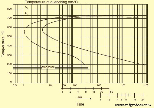
Fig 2 Isothermal transformation diagram
In addition to the curves stated above, IT diagram frequently contains intermediate curves corresponding to certain values of the transformed volume, say 20 %, 50 %, or 80 %. A decrease in the transformation rate causes displacement of the transformation start and finish curves to the right, i.e., toward greater duration. This phenomenon can be seen if the quenching heating temperature increases as a result of a decrease in the number of inclusions and growth of austenite grains. An increase in the transformation rate leads to displacement of the curves to the left. This phenomenon can be accounted for (i) by a decrease in the quenching heating temperature, (ii) the presence of carbides or inclusions, and (iii) refinement of the austenite grain. For a specified sample of steel the temperature which corresponds to a maxi mum transformation rate (the nose of the sigmoid curve) does not, as a rule, change significantly.
Continuous cooling transformation diagrams
Continuous cooling transformation (CCT) diagrams consider the transformation kinetics of eutectoid steel. The major transformation which takes place during annealing cooling of steel is a eutectoid precipitation of austenite into a mixture of ferrite and carbide. The eutectoid transformation kinetics is given by IT diagrams of austenite at a temperature of 727 deg C. The structure attained after tempering below 300 deg C is called tempered martensite. An acicular structure is seen after tempering at 300 deg C to 450 deg C. Tempering over the temperature interval of 450 deg C to 600 deg C shows a distinct dot structure. Austenite is in a thermodynamically stable equilibrium with the ferrite-Fe3C mixture. Stability of undercooled austenite is defined by a period of time during which the appearance of precipitation products in the diagram cannot be registered by conventional methods. The degree of austenite undercooling is the main factor which determines the steel microstructure. The necessary degree of undercooling is provided by either continuous cooling or isothermal treatment.
As seen earlier, in hypo-eutectoid steels the formation of pearlite is preceded by precipitation of hypo-eutectoid ferrite. With a decrease in the transformation temperature and an increase in the degree of undercooling, precipitation of hypo-eutectoid ferrite is suppressed. The amount of pearlite increases and the C content becomes less than that in pearlite of the eutectoid steel. In the region of the maximum transformation rate, the two curves merge. Thus, a purely pearlitic structure is formed in steel with 0.4 % C. In steels containing higher amounts of C, the precipitation of ferrite cannot be suppressed even if the C content decreases. Ferrite precipitation precedes the formation of pearlite even at a maximum transformation rate, but the amount of ferrite is less than that is formed at smaller undercooling.
These propositions are valid for the precipitation of cementite in hyper-eutectoid steels, but it can be suppressed even at relatively small undercooling. In this case, the C content of pearlite becomes higher than that in the eutectoid steel. As a result of suppression of the hypo-eutectoid ferrite precipitation under continuous cooling from the region of the gamma solid solution, the point Ar3 lowers much faster than the point Ar1 as the cooling rate is increased. With a certain cooling rate, both points merge into one point, which corresponds to the formation of a fine plate structure of the pearlite type free of ferrite.
Under continuous cooling the transformation process can also be visualized as diagram in temperature-time coordinates. Therefore the behaviour of cooling curves is to be analyzed to find characteristics of the transformation processes. In this diagram, the ferrite and pearlite start lines are shifted toward longer periods of time compared to the IT diagram. This is due to an increase in the temperature interval necessary for preparing the transformation processes in the austenite lattice. As a result, only part of the incubation period, which is needed for the IT to start, is effective. In this case, the incubation period is the mean of the effective lengths of time corresponding to different periods of time in the given range. This proposition can be used to calculate the behaviour of the transformation start line in the pearlite range from the IT diagram. The reverse calculation is also possible.
Similar to the pearlite range, in the bainite temperature range, the precipitation of undercooled austenite starts after a certain incubation period. Resemblance of the bainite and pearlite transformation kinetics consists not only in the presence of an incubation period but also in the character of the volume increase during isothermal soaking which is the fraction of the transformed volume of austenite increases first with acceleration and then with deceleration. At the same time, as in the case of the martensite transformation, retained austenite does not disappear completely during the bainite transformation. Every point in the bainite finish curve corresponds to certain amount of retained austenite. Similar to the pearlite transformation, the bainite transformation can take place both during isothermal soaking and under continuous cooling. Austenite which has not been transformed over the bainite range turns partially into martensite when the steel is cooled to room temperature. Since the austenite is inhomogeneous with respect to the C content after the bainite transformation, martensite is formed predominantly in C enriched regions.
For the high alloy steel, IT curves can be separated by a temperature interval in which undercooled austenite is highly stable. In this interval, pearlite precipitation does not take place for many hours, while undercooling is inadequate for the bainite transformation. In C steel, the bainite transformation proceeds concurrently with the pearlite transformation. Products of the pearlite transformation dominate at higher temperatures, and those of the bainite transformation at lower temperatures.
During the transformations of austenite on cooling in the martensite range, martensite component in the steel structure appears when the cooling rate achieves a certain value. The minimum cooling rate at which the martensite component is formed is called the lower critical rate of cooling. The rate at which transformations by the pearlite and bainite mechanisms are suppressed completely is referred to as the upper critical rate of cooling (quenching). If the conditions of austenite formation (austenitization temperature and the holding time at this temperature) and the cooling conditions (cooling rate exceeds the upper critical rate) are constant, the location of the martensite start point Ms depends only on the contents of C and alloying elements in the steel.
If the cooling rate is high, the formation rate of separate needles of martensite is also high, and transformation of austenite to martensite begins on reaching Ms-temperature. It continues on subsequent cooling to lower temperatures. As the temperature of the quenching medium is lowered, the amount of formed martensite increases first quickly and then slowly. With an increase in the quenching heating temperature (austenitization temperature), the transformation also shifts toward lower temperatures as more of the alloying elements are taken into solution. A certain amount of martensite can be formed during isothermal holding, but it is not high in C steels. Retained austenite is stabilized during isothermal holding. As a result, more martensite is formed during subsequent cooling. Formation of martensite stops at the point Mf. There is a relationship between some factors which influence the stabilization of martensite. The effect of stabilization increases with the amount of martensite in the structure or, the amount of martensite being equal, with temperature.
There is a close link between the CCT and IT diagrams. When resolving practical issues involved in heat treatment of steel, it is sometimes necessary to know how the continuous cooling rate affects the structure formed as a result of austenite transformation. For this, there have been efforts to establish the relationship between the transformation kinetics of austenite under isothermal conditions and under continuous cooling conditions. The efforts have started from the concept of additivity of the transformation processes at different temperatures. It has been presumed that holding of undercooled austenite at a preset temperature is part of the incubation period. However, it has been found, that calculated and experimental data coincide satisfactorily only if the pearlite transformation is continuous.
If the pearlite transformation is preceded by precipitation of eutectoid pearlite or the pearlite and bainite transformations occur concurrently, calculated data are at a discrepancy with the experimental data. It has been found that the discrepancy is due to the factors namely (i) holding of austenite during the time accounting for fractions of the incubation period causes acceleration of the subsequent intermediate transformation at the expense of preparatory processes, (ii) precipitation of hypo-eutectoid ferrite alters the austenite composition which delays the subsequent intermediate transformation, (iii) partial transformation of austenite over the intermediate range reduces the rate of the said trans formation at lower temperatures and facilitates an increase in retained austenite which is due to a redistribution of C and enrichment of the non-transformed part of austenite in carbon, and (iv) a change in the cooling rate over the martensite range affects stabilization of austenite in different ways.
For the above reason, special methods of constructing thermo-kinetic transformation diagrams of austenite subject to continuous cooling have been elaborated for non-eutectoid steels. From these diagrams it is possible to determine the critical rate of quenching cooling or continuous cooling which is necessary to complete a particular stage of austenite precipitation.
It has been seen that the CCT diagram is a function of the bar diameter. When steel is subjected to martensitic hardening, it is required to be cooled from the quenching temperature so that on undercooling to a temperature below the Ms point austenite has no time to precipitate and form a ferrite-carbide mixture. For achieving this, the cooling rate is to be less than the critical value. The critical cooling rate is the minimum rate at which austenite does not precipitate to a ferrite-carbide mixture. Of course, the cooling rate of steel products is non-uniform over their cross section. It can be higher than the critical rate on the surface and lower than the critical rate at the centre.
The critical cooling rate at different points of a product can be directly determined from an IT diagram. In the first approximation, it is given by the slope of the tangent to the C curve which denotes the austenite precipitation onset. This method gives a value which is around 1.5 times the true critical rate. The cooling rate can be determined more accurately if thermo-kinetic diagrams are used. Intercepts of the cooling curves with the lines of the thermo-kinetic diagrams show the start and finish temperatures of the corresponding transformation.
From the transformation diagram, it is possible to determine, for example, the rate which provides 40 % martensite in the structure or the rates at which the entire transformation occurs in the pearlite range, i.e., hardening is omitted altogether. Because the data on the critical hardening rate depend on cooling time and is to be associated with a specific temperature (at which direct measurements of the hardening rate are practically impossible), it is proper to specify the cooling time for a specific interval of temperature, for example, from the point A3 to 500 deg C. Point A3 in the diagram is the time reference. Then it is possible to directly determine the critical cooling time K (Km for fully martensitic hardening, Kf for initial appearance of ferrite, and Kp for full transformation in the pearlite range).
Since the cooling time and the progress of the subsequent cooling of the sample during end-face hardening are known, the outcome of hardening can be determined from the transformation diagram. It is to be remembered that a transformation diagram is valid only for particular conditions of melting and homogenization. Deviations in the composition or grain dimensions cause changes in the trend of thermodynamic curves. This is explained by the fact that an increase in the homogenization temperature and time and, consequently, enlargement of the grains enhance the stability of austenite. Conversely, refinement of grains lowers the critical cooling rate, since stability of austenite decreases with an increase in the extent of grain boundaries.
Hardenability
The depth of the hardened zone is termed hardenability. This is one of the most important characteristics of steel. Since the cooling rate is non-uniform along the cross section of a sample, austenite can pass into martensite in surface layers only, while at the centre of the sample austenite undergoes the pearlite transformation. In the first place, hardenability depends on the critical cooling rate. An examination of the temperature curves plotted for different areas of the sample shows that the cooling rate of the core of a large diameter product is lower than the critical value and hence the core is not martensitically hardened. Martensite is present in the surface layer only.
After hardening treatment, a bulky part with a large cross section can show the entire range of structures such as a smooth transition from martensite near the surface through troostite-martensite and troostite to pearlite at the centre. The geometry of samples can influence the character of the cooling curves. However, given the same surface-to-volume ratio, the curves coincide in general. The highest changes in the cooling rate are experienced by the diameter of samples.
Considering the above, for achieving a through hardening of bulky products or full martensitic hardening to the core of a product, it is essential to provide the critical hardening rate along the entire cross section of the product. IT and CCT diagrams can be used to determine this rate. The diagrams are usually plotted for different grades of steel, taking into account the progress of cooling in different sections and in different hardening media.
The hardenability of steels depends on the steel composition, specifically on the C content. In the steel hardenability diagrams, the hardenability of each grade of steel is normally presented as a hardenability band. These diagrams have been plotted for almost all existing grades of steel. They show how to achieve hardening of a product made of particular steel.
Hardenability of steel is also categorized by IT curves. The more the curve is shifted to the right along the X-axis, the greater is the hardenability of the steel. This is explained by the fact that the rightward shift of the IT curve is due to better stability of austenite.
An improvement in the stability of undercooled austenite and hence an increase in the critical hardening rate lead to a greater depth of hardening. Then hardenability depends on all the factors which improve the stability of undercooled austenite. As an example, the stability of austenite can be raised by alloying steel with chromium and tungsten. These elements lower the austenite precipitation rate and can make steel an air-hardening one. Steel with a normal content of impurities is hardened to strength ten times that of a pure Fe-C alloy.
Elevation of the hardening temperature favours an increase in the hardening depth due to the homogenization of austenite and enlargement of austenite grains. Refinement of grains impairs hardenability as grain boundaries affect the stability of austenite. The hardening depth also depends on the hardening medium used. The greater is the intensity of cooling, the greater is the depth of hardening. Besides, the hardening depth depends on the cross-sectional diameter of the products. The critical diameter is that of the greatest cross section which lends itself to through hardening in a given hardening medium. The critical diameter is different for different hardening media and characterizes the hardenability provided by a particular method only.
Hardenability has an effect on the mechanical properties of steel. In the case of through hardening, the properties do not differ along the cross section of a product. Otherwise they decrease from the surface to the centre. The analysis of the influence of hardenability on the properties of steels which have been tempered after hardening shows that a high temperature favours equalization of hardness along the cross section. However, the structure of weakly hardenable steels remains inhomogeneous. This is due to a grain structure appearing on the surface, where martensite is formed during quenching, while a lamellar structure remains at the centre. A grain structure is present along the entire cross section of through-hardening steel. This determines the character of changes in the properties of steels with different hardenability. The properties which are independent of the Fe3C form (YS, specific elongation, impact strength) differ.
The properties of tempered steels (fracture stress, YS, impact strength, reduction in area) are impaired if ferrite precipitates during quenching. The mechanical properties of a product depend on its cross-sectional area. To obtain the best mechanical properties in the tempered state, a grain structure is required to be provided along the entire cross section; i.e., through hardenability is to be ensured in the quenched state.
Grain size
It is necessary to know the material structure while analyzing any processes or properties associated with grain boundaries. Most of the steel materials have polycrystalline structure and they comprise a set of grains separated by boundaries. The grain boundary is one of the basic structural elements in polycrystalline steel materials. The grain boundary represents an interface between two differently oriented crystals. This is the region of crystal imperfection. It is capable of moving and adsorbing impurities. The boundary has a high diffusive permeability.
In polycrystalline steel materials, the boundaries determine the kinetics of many processes. For example, movement of grain boundaries controls the process of recrystallization. A high diffusive permeability of grain boundaries determines the kinetics of diffusion-dependent processes at moderate temperatures. Embrittlement of steel material is connected with enrichment of grain boundaries in impurities.
Grain boundaries are normally divided into two large groups namely (i) low angle boundaries, and (ii) large angle boundaries. Low angle boundaries are sub-grain boundaries with an angle of less than 10 degrees. They represent networks or walls of dislocations. The structure of large angle boundaries is much more complicated. The progress in understanding the structure of grain boundaries is connected with elaboration of the models describing the observed microscopic properties of the boundaries.
Grain size determination
The size of the grain that is formed under a given treatment is determined from micro-sections after their etching. For C and alloyed steels the reagent used is 1ml to 5 ml HNO3 +100 ml ethyl or methyl alcohol. Austenitic steel is etched in a copper sulphate-chloride solution containing 10 grams copper sulphate, 50 ml hydrochloric acid, and 50 ml water. When C and low alloy steels are etched, the reagents turn pearlite dark and make visible the ferrite grain boundaries, the martensite structure, and tempering products. The etching rate rises with the amount of nitric acid. The etching time is from several seconds to a minute. Etching of austenitic steel reveals the austenite structure and the austenite grain boundaries.
Carburization is also used to establish the austenite grain boundaries. In this case, samples are heated to 930 deg C in a carburizing medium (e.g., a mixture of 40 % BaCO3 and 60 % charcoal), cooled, and etched.
In addition, an oxidation method is used according to which micro-sections are heated in vacuum to a temperature 20 deg C to 30 deg C higher than the quenching temperature and are soaked for 3 hours. Subsequently air is fed to the furnace for 30seconds to 60 seconds, and the samples are cooled in water. Before quenching it is desired to heat samples in borax melt at 930 deg C to 950 deg C for 30 seconds to 40 seconds and then cool them in water. After these treatments micro-sections are polished and etched in a 15 % solution of hydrochloric acid in ethyl alcohol. Grain boundaries are seen as the oxide network.
Apart from this, use is made of the method of etching austenite grain boundaries, the method of the network of ferrite (for steels with a C content of up to 0.6 %) or Fe3C (for hypereutectoid steels), and the method of the pearlite network for steels which are closer in composition to eutectoid steels.
The grain size is determined by comparing the observed microstructure at a 100x magnification with standard scales (the scales are elaborated so that at a magnification of 100x the grain number N corresponds to the formula ‘n =8 X 2 to the power n’, with n the number of grains per sq mm of the micro-section area) or by counting the number of grains per unit area of the micro-section, or by calculating the mean nominal diameter of the grains or their number per cubic millimeter.
The austenite grain boundary structure which is produced on heating above the critical points is important since the austenite transformation products formed during cooling (martensite and pearlite etc.) appear inside austenite crystals. A coarse austenite grain determines a coarse plate structure of martensite during quenching or a coarse cellular network of ferrite (cementite) precipitates at the boundary of the initial austenite grains during annealing or normalization. The pearlite structure is also the coarser and the larger is the pearlite grain.
As is known, a coarse grain structure of steel (ferrite-pearlite, martensite, etc.) is characterized by lower mechanical properties. For this reason a fine-grain structure of steel is desirable in practice.
Grain size refinement
It is possible to refine a coarse-grained structure and this is widely used in the heat treatment of steel. The grain refinement, which takes place on heating steels above the Ac3 temperature, is related to a transition to the austenite state through nucleation of numerous centres of the austenite phase. Development of these centres leads to formation of a relatively fine grained structure. Above Ac3 temperature, the cross sectional size of the grain is 10 mm -30 mm. Initially the grain size is independent of the grain of the starting structure. It can be very fine irrespective of whether the starting structure of the steel is fine or coarse. A fine grain structure of the restored austenite provides a fine grain structure of cooled steel irrespective of the structural components (pearlite, bainite, or martensite) which are formed. This is due to the fact that all the transformation products nucleate within each separate grain of austenite.
Excess phases (ferrite in hypo-eutectoid steel and Fe3C in hyper-eutectoid steel) precipitate at boundaries of small austenite grains, and the pearlite transformation is accompanied by the appearance of smaller pearlite colonies. Fine austenite grains determine the formation of fine-needle martensite. This underlies the grain refinement effect which is associated with heating above Ac3 temperature. Heating the steel above Ac3 temperature during full annealing, normalization, or quenching is followed by recrystallization. With an initially coarse grain structure, recrystallization results in refinement of grains at a heating temperature corresponding to Ac3 temperature.
If the heating temperature is much higher than Ac3 temperature, then the grain is enlarged again, and the expected correction of the structure during the gamma to alpha transformation does not take place. Refinement of crystallites is especially pronounced when transformation to the austenite state starts in many centres inside the initial structure. The formed centres are to have a random orientation, which is not connected with the orientation of the alpha phase in the initial structure. Normally such centres are sufficiently large in number so that the grain size does not exceed 15 mm to 30 mm. During pearlite precipitation of austenite, breaking of an austenite grain into pearlite colonies, each of which can be considered an independent grain, also represents refinement of steel.
Strengthening mechanism in steel
There are four strengthening mechanisms in steel namely (i) solid solution strengthening, (ii) grain size refinement, (iii) dispersion strengthening, and (iv) work hardening.
Solid solution strengthening is a phenomenon which occurs when the number of impurity atoms in the lattice of the basic element is so small that they are incapable of forming both stable and metastable precipitation phases under any heat treatment conditions. However the impurity atoms favour improvement of the mechanical properties. The presence of impurity atoms in the matrix lattice leads to distortion of the lattice because of the difference in size between the atomic radii of the impurity and the basic component. This in turn leads to the appearance of elastic deformation fields, which retard movement of dislocations in slip planes under the action of applied stresses. In addition, the impurity atoms can obstruct movement of dislocations by forming impurity atmospheres around them. Both of the above factors play a leading role in solid solution strengthening.
Carbon which is statistically uniformly distributed in the lattice of the alpha iron has an influence on the structure and properties of alpha iron. Solubility of C in alpha iron is much lower than in the gamma iron. It forms interstitial solid solutions with both types of irons. However, whereas the gamma iron lattice has sufficiently large pores for implantation of C atoms, the cubic lattice of the alpha iron suffers. Upon introduction of C atoms, a tetragonal distortion takes place which is similar to the one of the martensite lattice except that in the former case the distortion is much smaller. In addition, inserting of C atoms causes the entire lattice of the alpha iron to somewhat expand. Hence, C affects the properties of the alpha phase. Actually, there is a dependence of the YS on the C concentration in the solid alpha solution. The influence which C exerts on plastic deformation resistance of the alpha phase is due to its strong interaction with dislocations as well as pinning of the dislocations and elastic deformations arising as a result of the tetragonal distortion of the alpha phase lattice after insertion of C atoms.
The presence of C in lattices of different structural components formed during thermal treatment of steel also leads to changes in their mechanical properties. As an example, the location of inserted C atoms primarily in one of the sub-lattices of interstitial sites during the martensite formation brings about additional tetragonal distortions of the martensite crystal lattice. This enhances plastic deformation resistance owing to the interaction between the stress fields around C atoms and those at dislocations. The influence of C dissolved in the alpha phase on the mechanical properties of steel is also witnessed in the case of the ferrite – pearlite transformation. The dissolution of part of the C in the alpha phase suggests that the solid solution strengthening of the phase is one of the factors providing the high strength properties of intermediate transformation products.
Grain size refinement of steel has a strengthening effect on steel. Impact strength is especially sensitive to the austenite grain size, and it decreases with grain enlargement. A decrease in the dimensions of pearlite colonies inside the initial austenite grain also favours a rise in impact strength.
Although the grain size has a considerable effect on impact strength, its influence is small if any on the individual mechanical properties such as hardness, fracture stress, YS, and specific elongation. Only the actual grain size affects steel properties, the inherited size has no effect. However, the technological process of heat treatment is determined by the inherited grain.
In the steels, precipitation of supersaturated solid solutions formed during quenching is followed by precipitation of disperse particles enriched in atoms of the alloying components. The strength (hardness) of the steels increases with the precipitation of these particles. The increment in the value of these characteristics increases as the dispersion and volume fraction of the particles increase. This phenomenon has been referred to as dispersion strengthening.
Precipitation of supersaturated solid solutions takes place during the heating (aging) of quenched steels. The strengthening is due to an increase in resistance to the movement of dislocations in a crystal when obstacles (barriers) of any type are formed. In aging steels, dislocations meet regions which retard their movement. The character of interaction between moving dislocations and precipitates of the second phase can be different depending on the phase morphology and structure. The total effect of aging on the strength properties of steels is determined by (i) the strength of the precipitates formed, (ii) the volume fraction of precipitates, (iii) the degree of precipitate dispersion, (iv) morphology, structure, and type of binding with the matrix, and (v) temperature.
When a solid solution of C in alpha Fe is cooled below A1 temperature, C precipitates as Fe3C with lowering of the C solubility and a decrease in temperature. This process takes place under sufficiently slow cooling, which is accompanied by diffusion processes, leading to the formation of cementite. In the case of abrupt cooling (water quenching) C has no time to precipitate. A super-saturated alpha solid solution appears. During subsequent storage at room temperature (natural aging) C tends to precipitate from the solid solution. Carbon enriched regions appear primarily in defective sections of the matrix. Precipitation of C from a supersaturated solid solution during natural aging results in an improvement of its strength properties and hardness. However, plastic properties such as reduction in area, specific elongation, and impact strength are deteriorated and the phenomenon of dispersion strengthening is seen.
As the heating temperature is increased (artificial aging), dispersion strengthening accelerates. This is due to the intensification of diffusion processes with an increase in temperature. The total process of C precipitation from the super-saturated solid solution in alpha Fe comprises several successive processes. Mechanical properties and hardness are not sensitive to structural changes which take place during the aging of the steels. Sharp changes in properties indicate alterations in the structural state of the steel.
A maximum change in mechanical properties during precipitation is achieved only if excess crystals in a highly disperse state precipitate. Subsequent coagulation of the crystals leads to degradation of the properties.
The influence of different solubilities of C in alpha Fe on the properties of the steel (dispersion strengthening) during low temperature aging is prominent in low C steels. In steels containing C higher than 0.4 %, the above effects are not noticed due to the influence of Fe3C particles formed during the pearlite transformation. Besides, nucleation of the precipitating phase can be inhibited owing to migration of C to the Fe3C-ferrite interfaces. As a result, the amount of C concentration at lattice defects decreases.
Cold plastic deformation greatly accelerates precipitation of a supersaturated solid solution. This is due to an increase in the density of dislocations, which are preferable sites of heterogeneous nucleation of precipitates as well as to an increase in the concentration of vacancies, which facilitates the diffusion of C to clusters. Mechanical properties change during aging after cold working in the same way as after quenching, that is, the YS, the fracture stress, and hardness are altered. With an increase in aging time, specific elongation and reduction in area decrease and the tendency to brittle fracture is enhanced. The rate of change is higher than in quenched steel. Also, the nature of the changes is different. Whereas in the case of aging after quenching, hardness reaches a maximum and then drops, after cold working hardness does not decrease with the aging time. As the aging temperature is raised, the maximum hardness of quenched steel lowers, while after cold working hardness is independent of the aging temperature. This is explained by the fact that a considerable amount of C is concentrated near dislocations. Few, if any, clusters nucleate in the matrix homogeneously. Consequently, clusters cannot grow at the expense of other clusters, i.e., they cannot coagulate.
An important method used to strengthen steels is deformation strengthening. Strengthening achieved with crystal deformation can be judged from the shape of stress-strain curves. The actual shape of these curves largely depends on the crystal lattice type of the metal, its purity, and thermal treatment.
In the case of cubic lattice steels, strengthening curves are parabolic, whereas for hexagonal lattice metals a nearly linear dependence is observed between the stress and the strain. This fact suggests that plastic deformation strengthening is determined mainly by the interaction of dislocations and is associated with the structural changes which retard the movement of dislocations. Metals with a hexagonal lattice are less prone to deformation strengthening than cubic lattice steels because the hexagonal lattice has fewer easy slip systems. In cubic lattice steels, the slip proceeds in several intersecting planes and directions.
There are three stages during the work hardening. The first stage is due to the easy slip. It depends on the orientation of the crystal relative to external forces and on the presence of impurities. This stage is characterized by a linear dependence of strain stresses on the strain at a small work hardening rate. Dislocations usually slip in primary systems.
In the second stage the work hardening rate is much higher than the first stage. Dislocations move in intersecting slip planes and, on colliding, form additional obstacles to their movement. This state is most extensive in the stress-strain curve. The ratio between the work hardening rate and the shear modulus (or any other elastic constant) is almost independent of the applied stress and temperature. It depends little on the crystal orientation and presence of impurities.
In the third stage changes are possible in the distribution of dislocations. They can either get around obstacles which retard their movement at the second stage or interact with dislocations. As a result, the work hardening rate is lower compared to which is observed during the second stage. At this stage, a partial relaxation of stresses can occur owing to the appearance of the secondary slip system. The reduction of distortion can have the result that deformation continues in the primary system, which gets rid of a certain number of dislocations passing to the system. A characteristic feature of deformation in the third stage is the development of a cross-slip representing the main mechanism by which dislocations bypass the obstacles formed in the second stage.
Heat treatment processes for steels
There are three basic processes for the heat treatment of steels. These are (i) annealing, (ii) quenching, and (iii) tempering.
Annealing
Annealing process of steels has different methods namely (i) diffusion annealing, (ii) softening, (iii) phase recrystallization annealing or full annealing (normalization, high temperature or coarse grain annealing, and pearlitization), and (iv) stress relief annealing and recrystallization annealing.
The objective of diffusion annealing is to eliminate, as far as possible, in-homogeneities in the chemical composition, in particular liquation in-homogeneities, which occur during crystallization of steels. This annealing is usually carried out in the range of the gamma solid solution at a temperature of 1100 deg C to 1300 deg C. Diffusion annealing can be used primarily to smoothen out a difference in the content of alloying elements, the difference being due to the inter-crystal liquation. This shows up as smearing of dendrites with an increase in temperature and heating time. Differences in micro-hardness are removed simultaneously. The overall hardness of the steel decreases since liquation regions possessing high hardness is removed. Some average hardness is attained. The success of diffusion annealing largely depends on the steel purity and liquation. This type of annealing is generally used to improve properties of medium purity steels.
Softening is used to produce the structure of globular pearlite. This structure is very soft and readily lends itself to deformation during drawing and cold rolling etc. Steels with a low C content become too soft after this annealing treatment. The globular pearlite structure is favourable in steels with a C concentration of more than 0.5 %. Another goal of softening is to produce a uniform fine structure with finely dispersed C after quenching. The simplest method of softening consists in holding for many hours at a temperature slightly above Ac1 temperature. In this case, martensite which is left from the previous treatment is removed and the work hardening caused by cold working is eliminated. Cooling after softening can be done in air starting from 600 deg C. Refinement of the structure subjected to softening is achieved only above the point A1 temperature.
Phase recrystallization annealing consists of a twofold gamma to alpha transformation, which takes place during this annealing. It leads to the appearance of a fine grained uniform structure differing completely from the initial structure. Refinement of the grain during normalization results in the disappearance of the Widmanstätten and coarse grained cast structures, which have poor mechanical properties. Inhomogeneity of the structure in the work hardened state is removed. The closer the annealing temperature is to Ac3 temperature and the shorter the holding time at this temperature, the finer is the grain. Refinement of the grain structure is also facilitated if the heating rate to the annealing temperature and the cooling rate from this temperature are increased.
In the case of normalization, cooling is done in air. Here it is important to allow for different rates of cooling along the cross section of large sized products. The arising thermal stresses are removed by stress relief annealing or high temperature tempering. To obtain a fine grained structure, rapid cooling is done only over the transformation temperature interval. The normalization heating temperature is not to be much higher than the transformation point, or else the grain may be too coarse (overheating). An excessively long holding time also have the same result. The optimal heating temperature is determined by the C content.
Stress relief annealing and recrystallization annealing removes macroscopic stresses which are present in cold worked steels due to the dislocation pile ups and crystal lattice distortions. Normally these stresses are very high. Changes in properties which occur during the cold working can be rectified during subsequent heating. The greater is the degree of cold working, the lower is the heating temperature. Depending on the temperature and time of annealing, various structural changes take place in a cold worked material. The changes are divided into recovery and recrystallization processes.
Recovery is a totality of any spontaneous process of variation in the density and distribution of defects before the onset of recrystallization. If recovery proceeds without the formation and migration of sub-grain boundaries inside the recrystallized grains, it is called restoring. If sub-grain boundaries are formed and migrate inside the crystallites, recovery is referred to as polygonization.
Restoring does not include an incubation period. Properties start changing right at the beginning of annealing. Restoring is accompanied by a redistribution of point defects whose concentration decreases subsequently from excess concentration to the equilibrium concentration. Simultaneously, dislocations are redistributed and unlike-sign dislocations are annihilated.
The structure of steel starts changing drastically from a certain annealing temperature. New rather equilibrium grains are seen along with extended cold worked grains. They differ from the grains of the deformed matrix by having a more perfect internal structure. As distinct from the polygonized structure, recrystallized grains are separated from the matrix with large angle boundaries.
The formation and growth of grains with a more perfect structure which are surrounded by large angle boundaries at the expense of initially cold worked grains of the same phase is called primary recrystallization. Recrystallization begins with an incubation period. The recrystallization rate increases initially from zero to a maximum and then decreases due to an ever rising number of new grains in contact with one another.
Inclusions of insoluble impurities (carbides, nitrides) lower the tendency to growth of recrystallized grains. This is especially important in the case of ferritic steels, which are prone to grain growth. Another phase can precipitate during recrystallization in alloy steels which are subjected to a strong cold working.
Sometimes the intensive growth of individual crystals can be seen after a strong deformation and long holding (for several days) at temperatures close to the melting point. This phenomenon is called secondary or collective recrystallization.
Quenching
Quenching is the strengthening treatment. It consists of cooling from the temperature range of the solid solution at such a rate that transformation in the primary and bainite ranges are suppressed and martensite is formed. In this state, steel has the property of the highest hardness. There is a distinction between (i) normal quenching, which is used mainly for treatment of medium C and high C steels, and (ii) quenching after a thermo-chemical treatment (carburization, high temperature cyaniding etc.), which is used for low C steels.
In case of normal quenching for providing a required cooling rate during quenching, different cooling media and methods are used. Water, oil, or air can serve as the cooling medium. Many alloy steels, which have a high stability of austenite, are subjected to step quenching. With this method of quenching, the temperature drop is less than in the case of direct cooling to room temperature and consequently quenching stresses are less.
Some quantity of austenite is retained during quenching even in steels with a relatively small C content. For this reason it is impossible to impart the maximum hardness to a product. Since austenite is stable at room temperature and passes to martensite at lower temperatures, steels are being given a subzero treatment. Under this treatment quenching is continued and steels with a high content of retained austenite are immersed in liquid nitrogen (N2) or quenching mixtures whose temperature is below 0 deg C.
For surface quenching (if it is necessary to harden only the surface layer to a preset depth), special quenching heating schedules are used. The surface of the steel is fully heated, while the core is cold and remains unquenched on subsequent fast cooling. The selection of steel for surface quenching is governed by the sensitivity of the steel to quick heating and cooling. For this reason the C concentration is limited to 0.7 % to prevent cracking of the steel.
Among the quenching defects, the main defects are excessive holding and overheating. They show up as enlargement of martensite needles and coarse grain fracture. This leads to a high brittleness of quenched steel and the formation of cracks. Cracks are frequently formed at the boundaries of initial austenite grains. A low quenching temperature or too short a holding time at the given temperature causes incomplete quenching. In this case, the quenched steel is insufficiently hard.
Carburization is the thermo-chemical treatment which is associated with surface saturation of steel with C and N2. These elements quickly dissolve in Fe by the interstitial method and are capable of rapid diffusion to a considerable depth. Low C steels are subject to carburization. Carburization is usually carried out at 900 deg C to 950 deg C. Gas carburization is used mostly, under which steel is heated in the atmosphere generated from a gas which contains predominantly methane (CH4) or from liquid hydrocarbons (kerosene and gasoline etc.). Carburization is aimed at enrichment of the surface layer with carbon. The required strengthening of the surface layer is achieved by quenching, which is done after the carburization. The specific volume of the quenched carburized layer is higher than the specific volume of the core, and hence considerable compression stresses arise in the layer. This improves the fatigue strength of the steels.
Cyaniding consists of the saturation of the surface of steels with C and N2 in a cyanide-containing salt bath. The C-N2 ratio in the diffusion layer is controlled by changing the medium’s composition and the processing temperature. Advantages of cyaniding over carburization consist in a shorter processing time and improvement in the wear and corrosion resistance (owing to the presence of N2 in the surface layer).
Tempering
The main purpose of tempering is to provide a disperse structure at a preset degree of cooling. In the case of low C steels, quenching serves as tempering even if the steel is not subjected to high temperature tempering it has a high viscosity and a relatively high strength.
When some of the steels are quenched in oil, a structure is formed even during transformation in the bainite range which is more disperse than the one formed after cooling in air. But the most disperse distribution of carbides and the most favorable properties are obtained after martensite tempering. The structure dispersion has the highest effect on the YS. An improvement of the fracture stress and YS and an increase in the fracture stress -YS ratio can be taken as a measure of the tempering efficiency. The tempering efficiency depends on the cross-sectional area and on the content of C and alloying elements in the steels.
Although to achieve a thorough quenching the critical quenching rate has to be exceeded over the entire cross section, full tempering does not require this procedure. As an example, in quenched steel which has martensite in the surface zone and pearlite in the core, the hardness of the core can sometimes be higher than that of the surface zone after tempering. This is particularly the case during a short tempering when precipitation of carbides from martensite proceeds faster than the coagulation of pearlite plates.
Tempering of hypo-eutectoid steels which do not contain free ferrite gives a uniform improved structure. In the presence of ferrite precipitates, the fracture stress-YS ratio decreases and the impact strength is lesser than in the surface zone. Hence, in selecting the content of C and alloying elements and particular conditions of austenitization and cooling, the size of the steel product to be tempered is required to be considered. For tempering to give adequate properties, it is often enough to suppress the formation of ferrite during continuous cooling. Only when a very high fracture stress is required an abrupt cooling is used for tempering. In this case, susceptibility to full tempering can be improved by raising the quenching temperature and thus enlarging the austenitic grain size.
Processo de manufatura
- Tratamento térmico de peças usinadas de precisão
- Benefícios do tratamento térmico a vácuo em punções e matrizes
- A importância do tratamento térmico eficaz para punções, matrizes, lâminas e aços para ferramentas
- Os Princípios para Alcançar o Puncionamento de Sucesso
- Os Princípios Fundamentais da Lixagem de Superfícies
- A Bomba de Calor Perfeita Água Quente
- Entendendo o tratamento térmico da solução, recozimento, nitretação
- Processo de tratamento térmico do aço
- 3 Etapas do Processo de Tratamento Térmico
- Tratamento térmico de alumínio e ligas de alumínio