


Aspectos importantes do projeto de alto-forno e equipamentos auxiliares associados
Aspectos importantes do projeto de alto-forno e equipamentos auxiliares associados
O projeto do alto-forno (BF) propriamente dito e seus equipamentos associados e auxiliares (Fig. 1) imediatamente a montante e a jusante do forno é importante para o funcionamento eficiente do BF. Além do forno propriamente dito, os equipamentos associados imediatos incluem (i) o almoxarifado, (ii) o equipamento de carregamento, (iii) o topo do forno, (iv) o sistema de refrigeração e (v) os equipamentos da área de fundição.
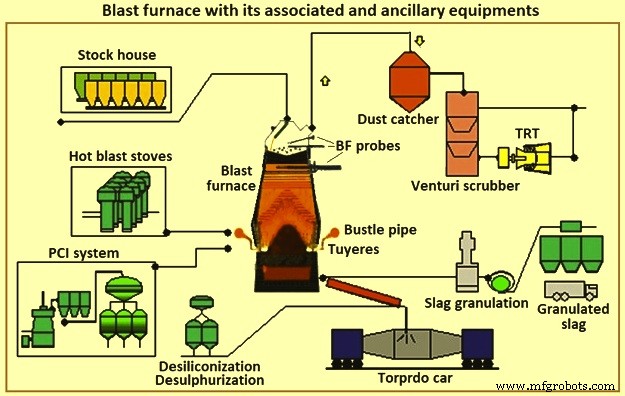
Fig 1 Alto-forno com seus equipamentos associados e auxiliares
A siderurgia BF consiste em um sistema composto por vários componentes que funcionam em harmonia. A aplicação e operação adequadas desses componentes são necessárias para apoiar o processo de fabricação de ferro. A seleção de componentes específicos depende de fatores como condições existentes, restrições físicas, requisitos de produção, custo, cronograma, confiabilidade e capacidade de manutenção. A interdependência dos componentes é tão importante para a operação bem-sucedida do sistema quanto sua capacidade individual. Existem requisitos importantes e práticas “normais” para cada área ou componente. Existem também algumas tecnologias alternativas que estão comercialmente disponíveis que têm vantagens e desvantagens inerentes.
O BF converte a carga de minério de ferro em ferro líquido (metal quente). Associadas ao BF estão as baterias de fornos de coque que convertem carvão em coque, e plantas de sinterização e pelotização, que preparam minério de ferro para o BF. O BF converte essas matérias-primas preparadas em um produto de maior valor. O metal quente de algumas das operações de BFs é usado em fundições para a produção de fundidos de ferro. Outras operações produzem um metal quente com baixo teor de silício que é convertido em aço na aciaria. Parte do metal quente é convertido em ferro gusa nas máquinas de fundição de suínos. Os subprodutos do BF são escória, gás de topo do BF, pó de combustão e torta de filtro. Esses subprodutos podem ter impacto econômico positivo ou negativo, dependendo das possibilidades locais de aproveitamento.
Alguns dos vários aspectos que afetam todas as considerações para o projeto ou redesenho do BF são (i) lucro, (ii) saúde e segurança dos funcionários, (iii) proteção ambiental, (iv) regulamentos estatutários, (v) necessidades do mercado e processamento a jusante, (vi) recursos humanos, de construção e manutenção disponíveis, (vii) tecnologias em mudança e obsolescência de equipamentos, (viii) matérias-primas disponíveis, utilidades e outros materiais, e (ix) assim por diante. Qualquer restrição grave em qualquer um desses aspectos pode colocar em risco a viabilidade da unidade BF (ou mesmo uma siderúrgica) ou impossibilitar ou exigir a construção de um novo BF.
BFs são normalmente agrupados por tamanho. Mini BFs produzem menos de 1.500 toneladas de metal quente por dia (tHM/dia), BFs pequenos produzem na faixa de cerca de 2.500 tHM/dia a 5.000 tHM/dia, BFs médios produzem na faixa de cerca de 6.000 tHM/dia a 8.000 tHM/dia, e grandes BFs produzem cerca de 9.000 tHM/dia a 12.000 tHM por dia. Em uma usina siderúrgica integrada, um número e tamanhos de BFs são necessários para fornecer o metal quente necessário para a produção de aço. Aciarias integradas com vários BFs são menos afetadas quando um BF sofre reparos de reembasamento ou quando há problemas de controle do forno. BFs pequenos têm reparos de reembasamento mais curtos do que BFs grandes e são considerados mais fáceis de operar. No entanto, o custo do metal quente de pequenos BFs é maior. A usina siderúrgica integrada deve operar o número mínimo de fornos com boa relação custo-benefício. Em alguns casos, são feitas atualizações para reduzir o número de fornos em operação.
Os BFs são reembalados periodicamente após o término de sua campanha (tempo entre o reparo do reembasamento). No passado, isso envolvia a substituição do revestimento interno de tijolos do forno principal. Nos últimos tempos, a reconstrução, substituição e manutenção preventiva extensiva de componentes são realizadas ao mesmo tempo. Com esta prática, a usina siderúrgica mais eficiente com menos BFs grandes perde um percentual maior de sua produção durante o reparo do reembasamento de BF do que a planta com mais fornos pequenos. Para ter tanto o baixo custo operacional quanto a mínima interferência durante os reembasamentos de BFs, a indústria tem trabalhado para maximizar a campanha dos BFs e reduzir a duração do reparo do reembasamento. A tendência atual clara nas siderúrgicas integradas é operar menos fornos grandes e utilizar técnicas e projetos que estendem a campanha de BFs indefinidamente.
Ao mesmo tempo, a redução da variabilidade do produto tornou-se mais importante e, portanto, estão sendo feitos investimentos em automação que melhoram o monitoramento e controle do processo. Operadores de BF, pessoal de manutenção, projetistas e pessoal de pesquisa aplicaram tecnologia moderna e métodos analíticos ao processo de BF para melhor monitorar e controlar o processo. Como resultado, o desvio padrão da qualidade do metal quente foi reduzido. Os sistemas de coleta de dados aprimorados também fornecem mais informações para fornecedores e fabricantes. Isso melhorou a seleção de materiais e o design dos BFs e equipamentos associados. A duração das campanhas aumentou para cerca de 20 anos antes, de 5 para 10 anos.
A fabricação de ferro BF é uma tecnologia com mais de 430 anos. Mesmo assim, o uso do BF ainda é o método mais comum utilizado nas siderúrgicas integradas para a produção de aço. Os processos atuais de usinas siderúrgicas integradas dependem do BF para fornecer quantidades previsíveis de metal quente de qualidade consistente. A variação em qualquer um dos aspectos do fornecimento de metal quente tem um sério impacto no restante dos processos de produção de aço. Assim, o BF continua a ser um processo chave nas modernas siderúrgicas integradas.
Às vezes está sendo afirmado que a tecnologia de processo BF está no fim de sua vida útil. Isto não é assim. O estudo de dados operacionais de 23 anos (1970 a 1993) de um par típico de BFs de médio porte mostrou que há um aumento médio de produtividade de 3% ao ano (Fig. 2a). Ao mesmo tempo, a redução média na taxa de combustível foi de 1% ao ano (Fig. 2b). Além disso, o tempo produtivo entre o reembasamento da BF (a campanha) foi estendido por meio de melhorias nos equipamentos, materiais e design. Como resultado, o custo total de produção de metal quente, corrigido pela inflação, melhorou ainda mais do que os dados operacionais indicam. Portanto, a tecnologia de processo BF não está morta, embora seja uma tecnologia com mais de 430 anos. Ele ainda está progredindo em todas as áreas a uma taxa considerável. O BF permanece hoje uma ciência dinâmica apoiada por tecnologias em constante aprimoramento.
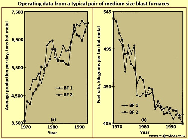
Fig 2 Dados operacionais de um par típico de altos-fornos de tamanho médio
Layout do BF
O layout de um BF é essencialmente um exercício de integração dos equipamentos necessários para manusear os diferentes materiais necessários para fazer o metal quente e o produto e subprodutos resultantes. O projeto mais eficiente acomoda adequadamente todo o processo e sua eficácia é julgada do ponto de vista do investimento de capital inicial e dos custos operacionais contínuos. O layout da loja BF depende de vários fatores, como (i) terreno do local, (ii) condições climáticas, (iii) método de entrega de matéria-prima, (iv) sistemas e locais de processamento de matéria-prima na planta, (v) sistemas de processamento a jusante e locais, (vi) requisitos de quantidade/fluxo para metal quente, (vii) tipo e tamanho da frota de entrega de metal quente, e (viii) assim por diante. A Fig 3 mostra um layout simplificado de uma planta BF.
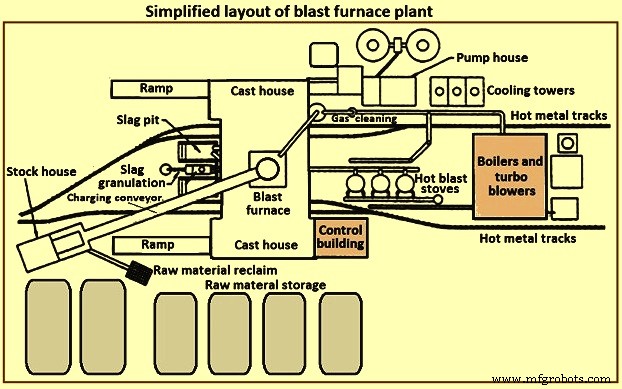
Fig 3 Layout simplificado de uma planta de alto-forno
Uma planta BF consiste tipicamente em várias seções. Essas seções são (i) armazenamento, manuseio e recuperação de matéria-prima, (ii) depósito, (iii) sistema de carregamento, (iv) forno próprio, (v) casa de fundição, (vi) processamento e manuseio de escória, (vii) manuseio de metal quente, (viii) fogões a quente e sistema de jato quente, (ix) planta de limpeza de gás, (x) utilidades, (xi) sistema de automação e controle, (xii) instalações de manutenção e (xiii) instalações de apoio ao pessoal.
Armazenamento e manuseio de matéria-prima
Matérias-primas como minério de ferro, sinter, pelotas, fundentes, carvão e coque, etc. são recebidas de fontes externas ou são produzidas dentro da siderúrgica integrada. Essas matérias-primas precisam de armazenamento controlado suficiente para suportar as operações de BF. A capacidade de armazenamento é necessária no caso de interrupções de entrega previsíveis ou interrupções imprevisíveis. Capacidade de armazenamento adicional pode ser necessária em caso de possíveis mudanças na origem de certas matérias-primas. Locais de armazenamento separados são necessários devido às diferentes características físicas ou químicas em materiais semelhantes. A mistura de materiais semelhantes pode causar problemas de controle de processo/metalúrgicos. As pilhas de armazenamento devem ser separadas para evitar a mistura de materiais diferentes. As pilhas devem ser colocadas em leitos preparados para permitir que os operadores de equipamentos de recuperação de matéria-prima diferenciem entre material primário e material residual. As pilhas são dispostas para minimizar a degradação do material e evitar o acúmulo de finos pelo vento. Pulverizadores de água e agentes de casulo podem ser usados para minimizar a coleta / transporte de poeira pelos ventos.
Várias técnicas diferentes estão disponíveis para o armazenamento e recuperação de matéria-prima. As técnicas de deposição incluem derrubamento de vagões, pontes de minério, transportadores de empilhamento, raspadores, etc. os sistemas devem ser dimensionados para garantir o rendimento necessário para a planta BF.
Estoque
O armazém é a unidade de armazenamento do operador de BF para alimentação direta da carga ao forno. Caixas de armazenamento são fornecidas para cada um dos materiais de carga para o BF. Caixas individuais são fornecidas para materiais semelhantes (ou seja, sinter, pellets) com diferentes propriedades metalúrgicas. O armazém fornece capacidade adequada para os vários materiais de carga em caso de interrupção de curto prazo do fornecimento das áreas de armazenamento de matérias-primas. As capacidades típicas de produção dos silos de estocagem, no caso de perda de alimentação de matéria-prima, são (i) coque – 2 horas a 8 horas, (ii) materiais de suporte de ferro (minério, sinter e pellet) – 4 horas a 16 horas, e fundentes e outros materiais diversos – 8 horas a 24 horas. Essas capacidades são baseadas na produção nominal do forno e variam dependendo da confiabilidade e do tempo de acesso para sua substituição do estoque ou de um fornecedor.
Os materiais de carga tendem a se degradar devido às condições climáticas e ao manuseio repetido. Quanto maior o número de vezes que o material é manuseado (armazenamento, recuperação, despejo, calhas de transporte, caçambas de ponte de minério, etc.), maior o percentual de finos na carga. O processo BF precisa de permeabilidade controlada e, portanto, carga controlada. A cobrança de finos excessivos, seja normalmente ao longo da carga ou concentrada em períodos de carga curtos específicos, pode ser prejudicial ao processo de BF e danos ao equipamento do forno. O armazém fornece a última oportunidade razoável para a remoção de finos antes do carregamento no forno. Sempre que possível, são instaladas peneiras vibratórias após os silos de armazenamento de coque, minério, sinter e pelotas para eliminar a maior parte dos finos. Os finos retirados são recolhidos para reciclagem. Alguns operadores de BF cobram multas em áreas específicas do forno para ajustar a permeabilidade do forno local e controlar as cargas de calor nas paredes do forno.
Medidores de umidade são frequentemente fornecidos no armazém para monitorar as quantidades reais de água carregadas no forno. Esta informação permite ajustes nas quantidades de carga para compensar as diferentes condições ambientais (ou seja, maior umidade do coque durante o período de chuvas).
Uma vez que são necessários diferentes tipos e quantidades variáveis do material de carga para suportar a operação contínua do BF, os materiais de carga devem ser fornecidos em uma sequência específica (que pode ser alterada com frequência para suportar os parâmetros operacionais do forno variáveis). Portanto, o armazém deve ser dotado de equipamentos confiáveis para extrair e alimentar quantidades precisas de materiais de carga específicos para atender a um cronograma específico. A Fig. 4 mostra a disposição simplificada do equipamento no armazém.
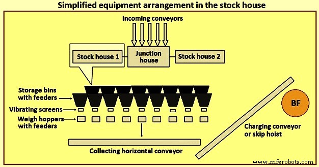
Fig 4 Disposição simplificada do equipamento no armazém
Anteriormente, o tipo mais comum de stock house era o tipo highline. Este tipo de armazém está localizado diretamente ao lado do forno. Vagões ferroviários ou pontes rolantes alimentam o compartimento de armazenamento enquanto os compartimentos de armazenamento alimentam diretamente um vagão de balança móvel. Um operador de carrinho de balança controla manualmente a porta de descarga do silo para alimentar quantidades específicas de material na tremonha equipada com balança localizada no carrinho de balança. Depois de coletar os tipos e quantidades adequados de material, o operador move o carro da balança para uma posição acima do "poço de caçamba" e despeja a carga, através de uma calha, em um carro de caçamba à espera. O vagão é então içado para o topo da fornalha.
O tipo highline de estocagem, em conjunto com um carro de escala, tem apresentado poucas opções para o fornecimento de peneiramento de cargas ferrosas (minério, sinter e pelotas). À medida que o conhecimento do processo de BF aumentou, foram desenvolvidos requisitos mais rigorosos para a carga. O conceito de “carga projetada” é bem reconhecido hoje na indústria. É normalmente aceite que existem limites à flexibilidade e adaptabilidade do armazém highline para suportar este requisito. Assim, o tipo highline do pátio de estoque foi substituído pelo armazém automatizado com esteira transportadora para fornecer materiais de carga ao BF.
O armazém automatizado é normalmente de dois tipos distintos e diferentes. O primeiro tipo é a substituição do carro balança sob os silos de matéria-prima por um sistema alimentador e esteira transportadora. Transportadores separados são fornecidos para cada tipo de matéria-prima (coque, materiais de rolamento de ferro e materiais de fluxo e aditivos, etc.) sobre os quais as fileiras de caixas de armazenamento são montadas, com alimentadores vibratórios para descarregar materiais pesados das caixas de armazenamento para os transportadores. Para os materiais de coque e ferro, uma peneira vibratória está localizada na descarga de cada transportador para peneirar o material e alimentar o material peneirado nas tremonhas de pesagem. Este tipo de sistema continua a alimentar as tremonhas de pesagem à frente dos vagões.
O segundo tipo de almoxarifado automatizado é uma grande estrutura de silos de armazenamento construída inteiramente acima do solo e bem afastada do BF. Isso normalmente é feito para os BFs, onde o transportador de correia é usado para transportar os materiais de carga para o topo do forno, em vez dos vagões. O método de enchimento das caixas de armazenamento é normalmente por um sistema de correia transportadora. As matérias-primas são extraídas das caixas de armazenamento por alimentadores vibratórios e transportadores de correia para as tremonhas de pesagem. As tremonhas de pesagem, por sua vez, descarregam o material na esteira principal por meio de uma esteira coletora. Os funis de pesagem são programados para pesar as matérias-primas na ordem correta na esteira transportadora principal até o topo do forno.
O fornecimento de um depósito automatizado pode fornecer alimentação mais eficiente de matéria-prima para o depósito e seleção, peneiramento, pesagem e entrega mais eficientes da carga ao forno. A empilhadeira automatizada pode ser localizada diretamente adjacente ao vagão de alimentação do forno, ou pode ser localizada distante do forno para carregamento através de uma correia transportadora.
A automação do armazém aumentou consideravelmente a capacidade de produção, melhorou a eficiência operacional e eliminou as variações operacionais causadas por operadores e equipamentos. No entanto, na prática, um armazém moderno e automatizado pode ser bastante complexo. A própria casa de estocagem pode ser alimentada por transportadores, que por sua vez descarregam em transportadores de manobra para distribuir materiais para várias caixas. O layout de transportadores e equipamentos no armazém pode ser organizado de várias maneiras. A colocação do armazém adjacente ao forno frequentemente resulta em congestionamento de layout e restringe a flexibilidade para modificações futuras.
Sistema de elevação
Os materiais de carga são normalmente içados ao topo do BF com a ajuda de vagões ou por esteira transportadora.
Ignorar o içamento do carro – O uso de skip car para BF evoluiu a partir da indústria de mineração. Os vagões BF são dimensionados para se adequar ao rendimento do forno. Obviamente, vários fatores, como a capacidade da talha, o projeto da ponte de salto e assim por diante, têm suas próprias influências ou restrições no tamanho do salto.
Normalmente, dois saltos operam de maneira oposta (para reduzir a potência de içamento necessária) em uma talha comum. Os saltos viajam em trilhos em uma ponte de salto, normalmente instalada em uma inclinação de 60 graus a 80 graus da horizontal. O salto completo acelera lentamente quando sai do poço, acelera o mais rápido possível atingindo e viajando na velocidade máxima durante a maior parte do levantamento. A talha desacelera o salto à medida que se aproxima do topo da ponte de salto. As rodas da caçamba são guiadas pelos trilhos de descarga e buzina à medida que a caçamba é virada no equipamento de carregamento superior do forno. À medida que a caçamba de elevação atinge e para na posição final de despejo, a caçamba vazia (descendo nas mesmas velocidades) está chegando ao fundo de seu curso no poço da caçamba, aguardando enchimento. O sistema de carregamento de salto é uma técnica confiável e eficaz para entregar a carga ao topo do forno. No entanto, falta flexibilidade para o operador, pois as caçambas podem conter apenas uma quantidade específica de material (a sobrecarga resulta em transbordamento ou cargas de içamento excessivas) ou torna-se ineficiente se forem necessários pequenos volumes de carga específica. A Fig. 5 mostra o esquema de içamento de vagão de caçamba.
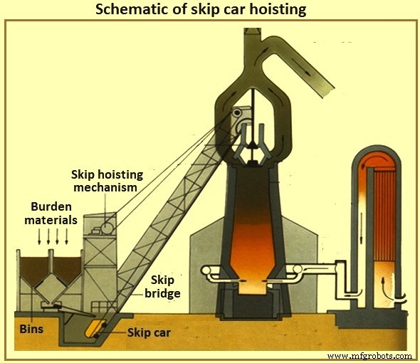
Fig 5 Esquema de içamento de carro de salto
Transportador de carregamento do forno – Com o transporte do armazém veio o transporte do sistema de elevação. Agora é comum que os depósitos estejam localizados longe do forno e uma grande esteira transportadora carrega a carga até o topo do forno. Se o topo do forno tiver cerca de 60 metros de altura, então uma esteira transportadora instalada em 8 graus de inclinação para a posição horizontal, o armazém deve estar localizado a pelo menos 427 metros do forno. Inclinações mais acentuadas da esteira são normalmente evitadas para minimizar a reversão do material. É normal carregar materiais diversos diretamente sobre e após o término de uma carga ferrosa na esteira transportadora para manter os materiais ferrosos no lugar até que eles atinjam o topo do forno.
Sistema de carregamento no topo do forno
O forno propriamente dito é operado com alta pressão positiva. O gás BF consistindo parcialmente de monóxido de carbono, dióxido de carbono e nitrogênio é gerado pelo processo BF juntamente com grandes quantidades de poeira arrastada. O operador do BF deve manter a pressão máxima devido aos benefícios do processo e conter os gases e poeira (tanto para o valor do combustível quanto para fins de controle ambiental). No entanto, o operador deve colocar regularmente material de carga dentro do topo do forno para reabastecer o processo interno, sem perder a pressão superior do forno.
Top tipo sino – Por vários anos, o tipo mais comum de tampo de forno tem sido o topo de dois sinos (Fig 6). À medida que a carga atinge o topo do forno (por caçamba ou por transportador), ela cai em um funil de recebimento e no pequeno funil de sino. O pequeno sino (fundição de aço cônico com cerca de 2,6 metros de diâmetro e 1,4 metros de altura para um BF de 5.000 tHM por dia) abaixa e permite que a carga caia na tremonha grande. O pequeno sino é levantado e vedado contra um assento fixo no pequeno funil de sino. Dependendo do volume da tremonha grande, cargas adicionais de carga são sequenciadas na tremonha grande pela campânula pequena. Durante todo este processo, o grande sino permaneceu fechado, vedando o forno. Quando os números corretos de carga da carga foram coletados, o sino grande (fundição de aço em forma cônica com cerca de 5,5 metros de diâmetro e cerca de 3,5 metros de altura para um BF de 5.000 tHM por dia) abaixa e permite que a carga deslize para baixo no sino em o topo do forno propriamente dito. Depois que a carga é descarregada, a campânula grande é levantada e vedada contra a parte inferior da tremonha da campânula grande. A Fig. 6 mostra os sistemas de carregamento superior tipo campainha BF.
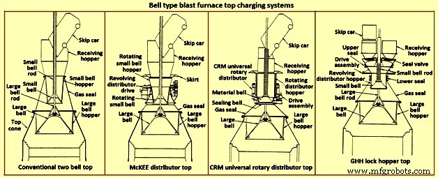
Fig 6 Sistemas de carregamento de topo de alto-forno tipo Bell
Obviamente, o controle de distribuição de carga com o forno para este tipo de tampo é limitado pela forma como a carga é colocada no sino grande (skip dump resulta em colocação desigual de carga neste tipo de tampo) e as curvas de queda do materiais de carga específicos (ou seja, coque ou carga de ferro) à medida que deslizam e caem do sino grande. Além disso, o topo de duas campânulas é suscetível à perda de vedação das campânulas grandes e pequenas e da embalagem entre a haste da campânula grande e o tubo da campânula pequena. O vazamento da campânula resulta da abrasão pelo deslizamento do material de carga sobre as superfícies de vedação da campânula. O vazamento da gaxeta da haste é resultado da abrasão dos finos de dentro do forno ou da coleta na haste do sino grande após a carga ser despejada na tremonha de recebimento.
Em um esforço para minimizar o desgaste da grande superfície de vedação do sino, o gás BF retirado de dentro do forno é introduzido entre os sinos para equalizar o espaço (reduzindo o diferencial de pressão através da grande superfície de vedação do sino). Este gás é liberado para a atmosfera antes da abertura do pequeno sino para permitir a introdução de mais carga. Algumas das opções disponíveis para melhorar as limitações do sistema superior de dois sinos são dadas abaixo.
O distribuidor McKEE – O distribuidor McKEE (Fig. 6) por vários anos foi a principal melhoria de distribuição de carga disponível para o topo do tipo dois sinos. No entanto, está sendo rapidamente substituído por outras tecnologias. Seu design incorpora a capacidade de girar o sino pequeno e o funil de sino pequeno juntos enquanto o vagão está descarregando. A carga é distribuída uniformemente no pequeno funil de sino, melhorando assim a colocação uniforme da carga no sino grande. Este tipo de tampo é propenso a pequenos e grandes desgastes de sinos e subsequente perda de efeito de vedação.
Topo do distribuidor rotativo universal CRM – O distribuidor rotativo universal CRM (Centre Recherches Metallurgiques – Bélgica) (Fig. 6) foi desenvolvido para eliminar a perda do efeito de vedação do pequeno sino. Dois sinos (um sino de vedação e um sino de material) são instalados no lugar do pequeno sino normal. Uma tremonha de carga giratória é montada na campânula de material. O sino de vedação está localizado abaixo do sino de material e veda contra um assento fixo. Durante a descarga da caçamba, a tremonha de carga e a campânula de fechamento do material são giradas para encher uniformemente a tremonha. Quando o enchimento estiver completo, a rotação da tremonha para. Quando é hora de despejar no sino grande, a tremonha giratória, o sino de material e o sino de vedação são abaixados. A campânula de vedação desce abaixo do assento fixo. No meio do processo de abaixamento, a descida da tremonha é interrompida e o sino de material e o sino de vedação continuam a descer até atingirem sua posição de parada. À medida que o espaço se abre entre o sino de material e a tremonha, a carga é descarregada uniformemente na tremonha grande. À medida que a carga sai do espaço, ela não entra em contato com a superfície de assentamento da válvula de vedação, mantendo assim a capacidade de vedação superior. Este estilo de tampo é capaz de manter 0,2 MPa de pressão interna.
A parte superior do CRM melhora a capacidade de vedação e a longevidade das duas tampas em forma de sino. No entanto, ele não fornece uma melhoria dramática na distribuição da carga do forno em relação ao distribuidor McKEE e não elimina a vulnerabilidade da grande superfície de vedação do sino.
A parte superior do funil de bloqueio GHH – O topo da tremonha de bloqueio GHH (Fig. 6) é a modificação do topo de duas campânulas. Reduz a dependência do sino grande para manter uma vedação de gás. A adição de tremonhas de bloqueio com válvulas de vedação separadas para cada local de despejo de caçamba fornece uma capacidade adicional de vedação da parte superior. O sino grande pode ser operado sem pressão diferencial em sua superfície de vedação (ou seja, a pressão no topo do forno é igual à pressão do funil do sino grande). A operação é dada abaixo.
Uma caçamba despeja a carga de carga na tremonha de bloqueio através de uma tremonha de recebimento e válvula de vedação aberta. A carga é colocada no pequeno sino giratório e enche uniformemente o funil do distribuidor rotativo acima do pequeno sino. Uma vedação entre a tremonha de bloqueio e a tremonha giratória pequena está aberta enquanto a rotação está em andamento. Quando a descarga da carga da caçamba termina, a válvula de vedação e a vedação entre a tremonha de trava e a tremonha pequena são fechadas. O gás equalizador é introduzido e a tremonha de bloqueio é pressurizada à pressão superior do forno. O pequeno sino é então abaixado para introduzir a carga no grande funil de sino. A pequena campânula fecha e a pressão da tremonha de bloqueio é aliviada para a atmosfera. A válvula de vedação no lado oposto (ou seja, na outra posição de descarga) é aberta. A vedação entre a tremonha de bloqueio e a tremonha pequena é aberta. A rotação do pequeno sino e da tremonha começa. O topo agora é capaz de aceitar a carga do outro salto.
Este tipo de tampo melhora a capacidade de vedação e a longevidade dos dois tampos. O topo do funil de bloqueio, no entanto, não fornece uma melhoria dramática na distribuição da carga do forno em relação ao topo McKEE ou CRM. Embora o sino grande não seja mais necessário para realizar uma função de vedação, a longevidade do efeito de vedação do sino pequeno ainda é crítica.
Armadura móvel – O principal passo dado para melhorar a distribuição de carga do tampo tipo sino foi o desenvolvimento de armaduras móveis (Fig. 7). Defletores ajustáveis são instalados na área da garganta do forno para desviar a carga depois que ela desliza para fora do sino grande. A blindagem móvel é ajustada dependendo do material de carga específico que está sendo descarregado e onde o operador deseja colocar a carga dentro do forno.
Vários fabricantes fornecem diferentes tipos de armaduras móveis. Segmentos de blindagem individuais podem ser movidos uniformemente (simultaneamente e igualmente) dentro do forno para colocar a carga em um padrão anular. Outros tipos de blindagem móvel estão disponíveis para fornecer controle individual das placas de blindagem para obter um padrão de distribuição não circular.
Algumas desvantagens associadas à blindagem móvel são (i) a maioria dos componentes mecânicos e de desgaste estão no ambiente hostil do cone superior do forno, (ii) é necessária alguma perda de volume de trabalho interno para fornecer folga entre a blindagem móvel e a linha de estoque do projeto (embora esta área do forno não possa ser classificada como uma zona de produtividade aproximada para consideração do volume de trabalho do forno, e (iii) capacidade limitada de desviar a carga para o centro do forno, particularmente quando o nível da linha de estoque já está alto. característica de pellets frequentemente nega o deslocamento limitado da armadura móvel.
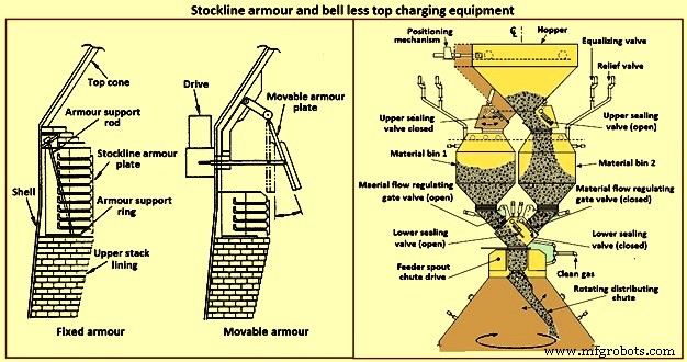
Fig 7 Armadura Stockline e equipamento de carregamento superior sem sino
Sistema de carregamento superior sem campainha – No início da década de 1970, a Paul Wurth S.A. de Luxemburgo desenvolveu o sistema de carregamento bell less top (BLT) (Fig. 7). Este tipo de topo do forno é uma mudança radical do topo do tipo sino. A carga pode ser colocada dentro do forno em qualquer padrão necessário pelo operador do forno. Anéis anulares, espirais, segmentos e posicionamento de pontos são padrões comuns alcançáveis por inclinação e rotação sincronizadas ou independentes de uma calha de distribuição de carga localizada com o cone superior do forno.
A vedação do topo do forno é mantida durante toda a campanha do forno. As atividades de manutenção são simples e de curta duração. Normalmente, o BLT consiste em uma calha de recebimento ou tremonha (recebendo carga das caçambas ou de uma correia transportadora), uma tremonha de bloqueio com válvulas de vedação superior e inferior, uma comporta de controle de fluxo de material, uma caixa de transmissão de acionamento da calha principal (uma caixa de água ou gás -unidade refrigerada usada para rotação e inclinação do chute) e o chute de distribuição de carga. Existem três tipos principais de BLT:(i) tremonha paralela, (ii) alimentação central e (iii) tipo compacto.
Normalmente, o tipo paralelo incorpora duas tremonhas de bloqueio (as tremonhas foram instaladas em alguns fornos para fins de rendimento e backup; uma tremonha do tipo "excêntrico" foi instalada para uma aplicação com folga restrita). Desde o início da década de 1980, vários BFs selecionaram o tipo de tremonha de bloqueio único de 'alimentação central' por suas melhorias na segregação de carga e controle de distribuição de carga, resultando em melhor operação do forno.
Um tipo 'compacto' de BLT top foi desenvolvido para fornos de pequeno e médio porte para permitir a introdução do BLT (e suas vantagens) em fornos onde os outros tipos maiores de BLTs não podem ser usados devido ao custo ou restrições físicas. As etapas na operação de BLT para um tipo de alimentação central são (i) a carga é descarregada de uma caçamba ou correia transportadora através de uma calha ou tremonha de recebimento, passando por uma válvula de vedação aberta na caçamba de bloqueio, (ii) após a carga ser recebida na eclusa tremonha, a válvula de vedação superior é fechada e o gás de equalização é introduzido para pressurizar a tremonha de bloqueio à pressão do forno, (iii) a válvula de vedação inferior se abre, (iv) a carga é descarregada da tremonha de bloqueio quando a porta de material foi ajustada para o abertura pré-selecionada para se adequar ao material de carga específico a ser descarregado, (v) a carga cai verticalmente através do bico do alimentador com a caixa de engrenagens da transmissão principal e cai na calha de distribuição de carga, (vi) a calha de distribuição de carga direciona a carga para o ponto(s) dentro do forno, (vii) quando a tremonha de travamento está totalmente descarregada (monitorada por células de carga e/ou monitoramento acústico), a válvula de vedação inferior é fechada, (viii) uma válvula de alívio é aberta para esgotar a tremonha de travamento atmosphe re (or through an energy recovery unit), and (ix) the upper seal valve opens and the sequence is repeated.
The advantages of BLT over other top charging systems include higher top pressure capability (i.e. 0.25 MPa), fuel savings, increased production, more stable operation, reduced maintenance in terms of cost and time, increased furnace campaign life, and improved furnace operational control when employing high coal injection rates at the tuyeres.
Gimbal system of charging – The purpose of the Gimbal system of charging is to facilitate controlled distribution of charge material into the BF via a Gimbal type oscillating chute through a holding hopper and variable material gate opening such that the pressurized charging system above can operate independently of the distribution system. It utilizes a conical distribution chute, supported by rings in a Gimbal arrangement, producing independent and combined tilting of the chute axis. The Gimbal distributor, as part of the overall BF top charging system, offers a fully integrated charging solution, generating considerable improvement in BF operation and maintenance cost. The Gimbal system utilizes a conical distribution chute, supported by rings in a Gimbal arrangement, producing independent, and combined tilting of the chute axis.
The Gimbal top incorporates a full complimentary range of furnace top distribution equipment including distribution rockers, upper seal valves, hoppers, lower seal valves, material flow gates and goggle valve assemblies, all discharging through hydraulically driven distribution chutes. The tilting chute is driven by two hydraulic cylinders, mounted 90 degree apart. This type of suspension and drive arrangement results not in a rotation of the tilting chute, but in a circular path by superposition of both tilting motions. Independent or combined operation of the cylinders allows the chute axis to be directed to any angle, or even along any path. Motion is supplied by two hydraulic cylinders, each operating through a shaft, connecting rod, and universal joint in order to drive the Gimbal rings. Through the movement of the hydraulic cylinders, the distribution chute allows precise material distribution with potential for an infinite number of charging patterns at varying speeds. These include ring, spiral, centre, spot, segment or sector charging, providing complete control of material charging into the furnace.
The whole distributor assembly is enclosed in a gas tight housing, which is mounted directly onto the top flange of the BF top cone. The housing contains a fixed inlet chute and a tilting distribution chute supported by rings in a Gimbal arrangement allowing independent and combined tilting of the chute axis. The assembly is made from a combination of stainless and carbon steel material with the fixed inlet chute and tilting chute body lined with ceramic material to give superior wear protection. A closed-circuit water cooling system supplies cooling water through the main shafts, Gimbal bearings, and universal joint bearings in order to cool the moving elements of the Gimbal distribution system.
The key features of the Gimbal design are (i) simple, rugged design, using levers driven by the hydraulic cylinders, (ii) drive cylinders are mounted outside pressure envelope, hence not subject to hot and dusty service conditions, (iii) Gimbal ring arrangement gives simple tilting motion in two planes, which when superimposed gives 360 degrees distribution, and (iv) wear on the tilting chute is equalized around its circumference giving a long extended operational life.
The BF Gimbal top is an automated, computer-controlled pressurized charging system designed to (i) receive charges of ore, coke, and miscellaneous materials in the holding hopper, independently of the distribution system below, (ii) release those discharges, as needed, to a dynamic distribution chute located below the holding hopper, and (iii) distribute material in prescribed patterns to the furnace stock-line in accordance with a predetermined charging matrix. Control of the Gimbal distribution chute is fully integrated into the overall furnace charging software. The system provides a high level of accuracy and control for the Gimbal movements and hence the positioning of the distribution chute. Gimbal material distributor is shown in Fig 8.
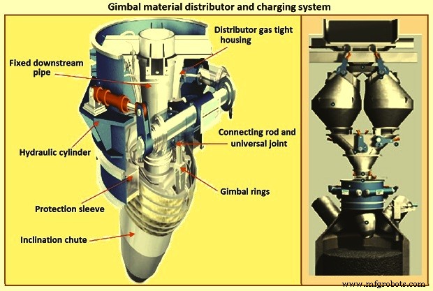
Fig 8 Gimbal material distributor and charging system
Furnace proper
The furnace proper is the main reactor vessel of the BF ironmaking process. Its internal lines are designed to support the internal process. Its external lines are designed to provide the necessary systems to contain, maintain, monitor, support, and adjust the internal process.
The BF process is a counter flow process. The process comprises of (i) burden at ambient conditions is placed in the furnace top onto the column of burden within the furnace, (ii) as the burden descends with the burden column, it is heated, chemically modified, and finally melted, (iii) further chemical modifications occur with the molten material, (iv) the molten products are extracted near the bottom, (v) melting of the burden material and extraction result in the descent of the burden column and the need for replenishment of the burden at the top, (vi) hot blast air is introduced through tuyeres near the bottom, (vii) BF gases are generated in front of the tuyeres and ascend through the burden and chemically modify the descending burden as well as themselves get chemically modified and cooled, (viii) BF gas (and dust) is extracted near the top of the furnace, and (ix) heat is extracted from the vessel in all directions (primarily through the lining cooling system) and along with the BF gas, liquid iron and liquid slag. Fig 9 shows cross section and types of BF.
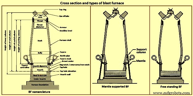
Fig 9 Cross section and types of blast furnace
Furnace type – Furnaces are constructed to be mantle supported or free standing. Mantle supported BFs characteristically have a ring girder (mantle) located at the bottom of the lower stack of the furnace. The mantle is supported in turn by columns which are on the main furnace foundation. The hearth, tuyere breast, and bosh are also supported by the foundation. Furnaces with mantle support column tend to have restricted access and reduced flexibility for improvements in the mantle, bosh, and tuyere breast areas.
Since thermal expansion is a major consideration in furnace shell design, the mantle style of furnace provides an interesting design consideration. The mantle support columns are relatively cool. The mantle tends to maintain a constant height, throughout the furnace campaign with respect to the furnace foundation. Thermal expansion of the stack due to process heat is considered to be based at the ‘fixed’ mantle (i.e. the top of the furnace raises with respect to the mantle). The effective height of the bosh, tuyere breast, and hearth wall shells (supported on the furnace foundation) increases due to the thermal expansion of the shell caused by the process heat. The lower portion of the furnace lifts upwards towards the fixed mantle. Hence, the provision of an expansion joint of some type is needed at the bosh / mantle connection or somewhere appropriately located in the lower portion of the furnace.
Free standing furnaces have been developed to eliminate the column and permit the installation of major equipment and furnace cooling improvements. This furnace type has a thicker shell for structural support. Installation and maintenance of a reliable cooling and lining system is necessary in order to sustain the structural longevity of the shell.
Two variations of the free standing furnace have been used. One type provides for a separate structural support tower to carry the furnace off-gas system and charging / hoisting system load. The other type (while it does employ a separate support tower for shell replacement purposes during relines) uses the furnace proper to support the off-gas system and charging / hoisting system loads. Special consideration to the furnace shell design is to be made regardless of the furnace type. The furnace vessel is subjected to internal pressures from the blast and gas, burden, liquid iron and slag. Dead and live load during all operating, maintenance, and reline stages are to be considered as well.
Furnace zones – The major zones of the furnace proper are (i) top cone, (ii) throat, (iii) stack, (iv) mantle / belly, (v) bosh, (vi) tuyere breast, (vii) hearth walls, (viii) hearth bottom, (ix) foundation.
Top cone – The top cone or dome is the uppermost part of the furnace proper. It supports the furnace top charging equipment, and the BF top gas collection system. Stock rods (stockline recorders or gauges) are normally placed here to monitor the upper level of the burden in the furnace. These devices are the units which provide the permissive or indication signals to charge the next scheduled burden input to the furnace. Typically, they are weights lowered by special winches, or microwave units. Some furnaces incorporate radio-active isotope emitters and detectors mounted in the furnace throat to monitor the burden level. Infrared camera can be installed in the top cone to monitor the BF top gas temperature distribution as it escapes the furnace burden stockline.
The top cone is the coolest zone of the furnace proper but can be exposed to extremely high temperatures if burden ‘slips’ (rapid, uncontrolled burden descent after a period of unusual lack of descent). The newly charged burden falls through this zone and the BF top gas is carried away from this section.
Throat – Steel wear plates or armour are installed in this zone. Here, abrasion of the furnace lining from the charged burden is the prime cause of deterioration. Furnace operators work to maintain the upper level of the burden (the stockline) in this region. Movable armour can be installed in this area in order to deflect the burden falling from a large bell. With the installation of the BLT, wear of the stockline area can be greatly reduced. Some BF users select to eliminate the armour plates and use an abrasion resistant refractory lining instead.
Stack – The stack (sometimes called shaft or the ‘in-wall’) is the zone between the mantle or belly on a free standing furnace and the stockline area. Smooth, uniform lines (the process ‘working surface’) of the stack are essential for uniform and predictable burden descent, BF gas ascent, and stable process control throughout the furnace campaign. Process considerations dictate a larger diameter at the base of the stack than at the top. Typical stack angles are in the range of around 85 degrees from the horizontal.
Mantle / belly – The mantle or belly area provides the transition between the expanded stack and bosh sections. Maintenance of the effectiveness of the cooling / lining system is particularly important for the mantle type furnace in order to protect the mantle structure. Thermal protection is important for the free standing furnace type as well. However, the free standing design is less complicated and more accessible in this area.
Bosh – The bosh area lies between the tuyere breast and the mantle / belly of the furnace. The bosh diameter increases from bottom to top. The inclination of the bosh permits the efficient ascent of the process gases and has been found to be necessary in order to provide the needed zone service life (the process gases are extremely hot and internal chemical attack conditions are severe). Typical bosh angles are in the range of around 80 degrees from the horizontal. Boshes are of two basic types, namely (i) banded and (ii) sealed. They can be cooled by different techniques.
Banded boshes are found in older mantle supported furnaces (they cannot be applied to free standing furnaces). A number of steel bands are placed in incrementally increasing diameters (smallest at the bottom of the bosh and largest at the top) and are tied together with connecting strips. Gap between the bands permits the introduction of copper cooling plates. Ceramic brick lining is to be used as air infiltration results in oxidation of carbon based linings. Gas leakage through the banded bosh can be high. This type is not suitable for BFs with high blast pressure / high top pressure. Banded boshes provide adequate flexibility to eliminate the requirement for a shell expansion joint in the lower portion of the furnace.
Sealed boshes, using continuous steel shell plate instead of separate bands, are employed to permit the use of improved cooling / lining systems, higher furnace operating pressures, and the free standing furnace type. Sealed boshes retain valuable gases with the furnace, hence improving the metallurgical process. As well, the seal bosh, since it precludes air entry into the lining, supports the use of carbon based refractories.
Tuyere breast – Hot blast air is introduced to the furnace through tuyeres (water-cooled copper units) located within the tuyere breast. The number of tuyeres needed depends upon the size (production capacity) of the furnace. The tuyere breast diameter, tuyere spacing, and number of tuyeres are influenced by the expected raceway zone size in front of each tuyere.
Tuyere stocks (Fig 10) convey the hot blast air from the bustle pipe to the tuyeres. The tuyeres are supported by tuyere coolers (water-cooled copper units) which are in turn supported by steel tuyere cooler holders (either welded or bolted to the furnace shell). Special consideration are to be made in the tuyere breast shell and lining design in order to maintain effective sealing of the different components in order to prevent escape and loss of the furnace gases.
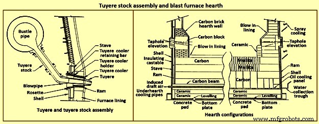
Fig 10 Tuyere stock assembly and blast furnace hearth
Hearth – The hearth (Fig 10) is the crucible of the furnace. Here, hot metal and liquid slag are collected and held until the furnace is tapped. The hearth wall is penetrated by tap holes (frequently called iron notches) for the removal of the collected hot metal and liquid slag. The number of tap holes is dependent upon the size of the furnace, hot metal, and liquid slag handling requirements, physical and capital constraints etc.
Several furnaces are equipped with a slag or cinder notch (normally one per furnace, although some furnaces can have two). The slag notch opening elevation is normally sufficiently higher than the iron notch elevation. In earlier days, when slag volumes were high, the slag was flushed from the slag notch periodically. This simplified the iron / slag separation process in the cast house. More commonly now, however, the slag notch is retained solely for initial furnace set-up procedures or for emergency use in case of iron notch or other furnace operating problems.
Hearth bottom – The hearth bottom supports the hearth walls and is flooded by the iron within the furnace. As the campaign progresses, the hearth bottom lining wears away to a fixed equilibrium point. The remaining refractory contains the process and with sufficient cooling or inherent insulation value protects the furnace pad and foundation.
Cooling system
The application of specific cooling techniques to individual furnace zones is dependent upon several factors such as campaign life expectancy, furnace operational philosophy, burden types, refractories, cost constraints, physical constraints, available cooling media, and preferences etc. Different cooling techniques can be provided for different zones to assist the lining to resist the specific zone deterioration factors. Normally, the provision of adequate cooling capacity is necessary in each of the applicable furnace zones if the lining system located there is to survive. Where the thermal, chemical, and to some extent the abrasive conditions of the process are extreme, sufficient cooling is to be provided to maintain the necessary uniform interior lines of the furnace and to protect the furnace shell.
Typically, the top cone and throat areas of the furnace are not cooled. The hearth bottom can be ‘actively’ cooled by under hearth cooling (air, water, or oil media) or ‘passively’ cooled by heat conduction though the hearth bottom lining to the hearth wall. The basic cooling options for the balance of the furnace are (i) no cooling (typically the upper portion of the stack is not cooled in several furnaces, (ii) shower or spray cooling, (iii) jacket or channel cooling, (iv) plate cooling, and (v) stave cooling.
Shower or spray cooling – Water is directed by sprays or by overflow troughs and descends in a film over the shell plate. Effective spray nozzle design, numbers and positioning are important for proper coverage and to minimize rebound. Proper deflector plate design is necessary to ensure efficient cooling water distribution and to minimize splashing. Shower cooling is frequently employed in the bosh and hearth wall areas. Spray cooling is normally applied for emergency or back-up cooling, primarily in the stack area. Exterior shell plate corrosion and organic fouling are common problems which can disrupt water flow or insulate the shell from the cooling effect of the surface applied cooling. Water treatment is an important consideration to retain effective cooling.
Jacket or channel cooling – Fabricated cooling chambers or indeed structural steel channels or angles are welded directly to the outside of the shell plate. Water flows at low velocity though the cooling elements in order to cool the shell and the lining. Jacket or channel cooling is frequently applied to the hearth walls, tuyere breast, and bosh areas. Scale build-up on the furnace shell and debris collection in the bottoms of the external cooling elements can compromise the cooling effectiveness. Hence periodic cleaning of the cooling elements is necessary.
The critical area of concern in the cooling schemes mentioned so far is the necessity for the shell plate to act as a cooling element. If extreme heat loads are acting upon the inside face of the shell, then there exist an extremely high thermal gradient across the shell. This effect results in high thermally induced shell stresses and eventual cracking. The cracks start from the inside of the furnace and propagate to the outside. The cracks remain invisible (other than a ‘hot spot’) until they fully penetrate the shell plate. Through cracking of the shell plate results in the leak of the BF gas, exposed shell carburization, and disruption of the cooling effect (particularly spray or shower cooling). Shell cracking into a sealed cooling jacket or channel is difficult to locate and can result in long furnace outage time for repair. Entry of water into the furnace (frequently when the furnace is off-line and internal furnace gas pressure cannot prevent entry of cooling water though shell cracks) can have detrimental effect upon the furnace lining. Water in the furnace can be potentially dangerous due to explosion risk (steam or hydrogen). Since shower and jacket cooling rely on the shell plate to conduct the process heat to the cooling media, the plate and stave cooling are configured to isolate the shell from process.
Plate and cigar cooling – Installation of cooling elements though the shell of the furnace (Fig 11) has been a major furnace design improvement resulting in effective cooling of the furnace lining and protection of the shell plate. Cooling is provided along the length of the cooling element penetration into the lining. The inserted elements provide positive mechanical support for the refractory lining. Typical cooling plate manufacture is cast high conductivity copper. Single or multiple passes of cooling water can be incorporated. Cooling boxes with larger vertical section have been produced from cast steel, iron, or copper.
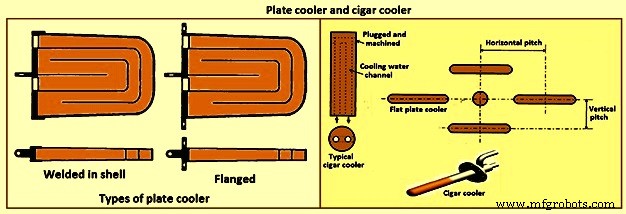
Fig 11 Plate cooler and cigar cooler
Cigar type (cylindrical) coolers (Fig 11) of steel and /or copper have also been successfully used. The philosophy of dense plate cooling (i.e. vertical pitch of 350 mm to 400 mm centre-to- centre, and horizontal pitch of 600 mm (centre-to-centre) has improved the cooling effect and increased lining life.
Copper cooling plates have traditionally been anchored in the shell plate with retainer bars or bolted connections to permit ready replacement if plate leakage occurs. More recently, plates have been designed with steel sections at the rear of the plate for welding directly to the steel shell. While sometimes taking longer to replace, this type provides a positive seal against BF gas leakage. Plate coolers are typically installed in areas above where the liquid iron collects in the furnace. Hence the mid-point of the tuyere breast, right up to the underside of the throat armour is the range of application.
Stave cooling – Cast iron cooling elements (Shannon plates or staves) have been used for several years in the bosh and hearth wall areas. These castings have cored cooling passages of large cross-section. While their service life have been not remarkable in the bosh, multiple campaigns have been normal for the hearth wall. These staves frequently suffered from low flow rates of marginal quality cooling water (scaling and debris deposition / build-up) and sometimes casting porosity. Water leaks into the hearth wall can be a considerable problem.
In the 1950s, the then USSR developed a new type of stave cooler (Fig 12) and ‘natural evaporative stave cooling’. For this design, castings were of gray cast iron containing steel pipes for water passes. The pipes were coated prior to casting to prevent carburization of the cooling pipe and metallurgical contact with the stave body material. The staves were installed in horizontal rows with the furnace and the cooling pipes projected through the shell. Vertical column of staves were formed by the inter-connection of the projecting pipes from one stave up to the corresponding stave in the next row. Staves can be applied to all the walls in the zones below the armour. Staves in the hearth wall and tuyere breast are supplied with smooth faces. Staves in the bosh, mantle / belly and stack normally have rib recesses for the installation of refractory.
Evolution of the stave cooler design has been dramatic. Staves in the higher heat load areas are now typically cast from ductile iron for improved thermal conductivity and crack resistance. While early stave design used castable refractory (installed after stave installation within the furnace), ribs now normally incorporate refractory bricks, either cast in place (with the stave body at the foundry) or slid and mortared in place prior to installation in the furnace. Fig 12 shows stave cooler and generations of stave development.
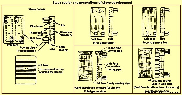
Fig 12 Stave cooler and generations of stave development
Staves are normally expected to retain a refractory lining in front for some time. After loss (expected) of the lining the staves are designed to resist the abrasive effects of descending burden and ascending dirty gas. As well, they are to absorb the expected process heat load and resist thermal load cycling and shock. Four generations of staves (Fig 12) are normally recognized in the industry.
First generation staves are no longer normally used. These staves have four cooling body circuits (with long radius bends which do not effectively cool the stave comers. These staves are made of gray iron castings with castable rib refractory. Second generation staves have four cooling body circuits with short radius bends for improved comer cooling. These staves are made of ductile iron castings with cast-in or glued-in rib bricks. Third generation staves have two-layer body cooling incorporating four or six cooling body circuits (stave hot face) and one or two serpentine cold face circuits (stave cold face) for additional or back-up cooling in the event of hot face circuit loss. These staves have additional edge cooling (top and bottom). The more frequent use of these staves is as cooled ledges to support a refractory lining. These staves have cast-in or mortared-in rib bricks. Fourth generation staves have two-layer cooling (similar to third generation). These staves have cooled ledges and cast-in wall brick lining eliminating the need for a manually placed interior brick lining.
Staves incorporating hot face ledges are more effective in retaining a brick lining than the smoother rib faced bricks. However, once the brick lining disappears, the ledges are very exposed within the furnace. The ledges disrupt burden descent and gas ascent. Exposed ledges tend to fail quickly. They are frequently serviced by cooling water separate from the main stave cooling circuit(s). In this way leaking ledge circuits can be more easily located or isolated. Some stave manufacturers are now providing separate ledge castings so that ledge cracking and loss does not damage the parent staves. As well, there is some present change in philosophy to abandon the application of ledges entirely.
Variations of the basic stave generation types are common. For example, staves of fourth generation type utilizing a refractory castable for the wall ling have been employed successfully. Alternatively, brick linings have been anchored to the stave bodies. Such approaches can be used to substitute for brick support ledges.
A ‘fifth’ generation of staves design has been the developed. It is the copper stave (Fig 13). The development of copper staves was carried out both in Japan and Germany for use in the region of bosh, belly, and lower stack to cope with high heat loads and large fluctuations of temperatures. While Japan has gone for cast copper staves, German copper staves are rolled copper plates having close outer tolerarnces and with drilling done for cooling passages. Drilled and plugged copper staves are typically designed for four water pipes in a straight line at the top and four water pipes in a stright line at the bottom. Materials for internal pipe coils include monel, copper, or steel. Unlike cast iron staves, copper staves are intended to be bonded to the cooling pipe.
The development of the cast-in copper stave has considered the following aspects. As per the first aspect, for the prevention of deformation, appropriate design of the stave length and bolt constrained points is important. The first aspect is that the use of the cast-in steel pipe copper stave with its own design is beneficial for effectively reducing the risk of deformation. Fig 13 shows the constrained points of a rolled copper stave and the cast-in steel pipe copper stave. A rolled copper stave is constrained to the shell by mounting bolts and pins. To prevent the weld at the base of a rising pipe from being damaged by stresses, rising piping is connected to the shell by an expansion joint. Due to this structure, the upper and lower ends of the staves are freely displaced, causing the staves to be easily deformed. The large thermal load which is repeatedly applied to the copper stave in the course of the fluctuation in the BF operations etc., causes plastic strain to be gradually accumulated, and results in large deformation. There are cases in which the deformation at the upper end has reached 50 mm or more and a weld has been broken, under the condition of an overly long stave, an in-appropriate bolt position, or high heat load exceeding the design condition.
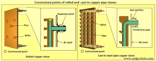
Fig 13 Constrained points of rolled and the cast-in pipe copper stave
Presently, the most popular type of copper stave is the rolled copper stave, the manufacturing process of which involves drilling holes on a copper plate. The water channel ends of these staves are plug-welded. The cast-in steel pipe copper stave, which has been developed, is made by casting bent steel pipes into the copper, a completely different manufacturing process from that of the conventional rolled copper stave. This unique manufacturing method has enabled achieving high energy efficiency and long life of BFs, which cannot be achieved using the rolled copper stave.
Natural evaporative stave cooling (NEVC) is a technique where boiler quality water is introduced into the bottom row of staves and flows by natural mean up the vertical cooling circuits. As the process heat conducts through the stave and cooling pipe into the water, the water in turn heats up. As the water warms, it expands. Since cooler water is being introduced below, the warm water tends to move upwards. At some point in the vertical cooling circuit, the water is at the boiling point. As the water changes its phase to steam, due to the latent heat of vapourization, additional heat is absorbed (driving the phase change). After boiling begins, two-phase flow (water and steam mixture) ascends the cooling pipes to the top of the furnace. Normally located on the furnace top platform are steam separator drums used to extract and vent the steam to atmosphere. Make-up water is introduced to the drum (to replace the discharged steam). The water is piped back by gravity to the furnace bottom and is fed once more to the staves. This cooling technique is very efficient and has low operating costs. There is no pumping equipment. The improvements in this system has been to boost the flow of the cooling water with recirculating pumps (forced evaporative cooling, FEVC) in order to ensure uniform cooling water flow and to cool the recirculating water (forced cold water cooling – FCWC). Both of these approaches have resulted in improved stave and lining life.
Staves provide an excellent protection for the shell plate throughout their service life (which is extended while the interior brick lining remains in place). Stave application has been implemented in all areas of the furnace from hearth wall up to and including the upper stack.
One drawback for conversion of an existing plate cooled furnace to stave cooling can be the cost of a new shell. However, if the existing shell is already in distress and is to be replaced in any event, the conversion cost is not a major factor.
Cast house
The cast house (Fig 14) is the area or areas at the BF where equipment is placed to safely extract the hot metal and liquid slag from the furnace, separate them, and direct them to the appropriate handling equipment or facilities. The hot metal and liquid slag are removed from the furnace through the tap hole. Only infrequently today slag is flushed from the slag notch. The equipment for tap hole is to be reliable and need minimum maintenance. Furnaces typically tap eight times to eleven times per day.
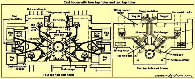
Fig 14 Cast house with four tap holes and two tap holes
Mud gun – The mud gun is used to close the tap hole after tapping is complete. A quantity of the tap hole mass is pushed by the mud gun to fill the worn hole and to maintain a quantity of the tap hole mass (the mushroom) within the hearth. The mud gun is normally held in place on the tap hole until the tap hole mass cures and the tap hole is securely plugged. A hydraulic mud gun uses hydraulic power to swing, hold, and push the tap hole mass. Typical injection pressure of tap hole mass is of the order of 20 MPa to 25 MPa, permitting it to push viscous mass into the furnace operating at high pressures. The hydraulic gun is held against the furnace with the equivalent of 15 tons to 35 tons of force. This type of mud gun can be swung into place in one motion.
An electro-mechanical gun has three separate electric drives for unit swing, barrel positioning, and ramming. Hence several separate motions are needed for accurate positioning of the mud gun at the tap hole. Tap hole mass injection pressure is in the range of only 5 MPa to 8 MPa. The electro-mechanical mud gun is latched to the furnace to keep it in place during plugging.
Tap hole drill – Tap hole drill is used to bore a hole though the tap hole clay into the hearth of the furnace. A drill unit is swung into place hydraulically and held hydraulically in the working position. A pneumatic motor feeds the hammer drill unit (with an attached drill rod and bit) into the hole. Compressed air is fed down the centre of the drill rod and the drill bit to cool the bit and blowout the removed tap hole mass. When the tap hole drill rod has penetrated into the hearth, the drill rod is retracted and the drill swings clear of the hot metal stream.
Soaking bar technique – The application of the soaking bar practice has improved the tapping process. When the tap hole mass is still pliable after plugging, a steel bar is driven into the tap hole by the tap hole drill. While the bar sits in place during the time between casts, it heats up by conduction from the hearth hot metal. This permits curing of the tap hole mass along its entire length (as opposed to curing with the furnace and setting at the outside near the furnace cooling elements). The cured tap hole mass is more resistant to erosion during tapping, hence improving tap flow rate control. Less tap hole mass is needed to replug the hole. When the tap hole is to be opened, a clamping device and a back hammering device on the tap hole drill extract the rod. The timing for tap hole opening can be more easily controlled (predicted) than by conventional drilling. This feature is important for smooth furnace operation and for scheduling of hot metal delivery to downstream facilities.
Same side tap hole equipment – Mud gun and drills have normally been installed on opposite sides of the tap hole. Design development has permitted installation of these equipments on one side of the tap hole. The drill swings over the mud gun or vice versa. This type of installation facilitates improved access for tap hole and trough maintenance and the improved application of trough and tap hole area flue collection.
With the advent of tuyere access platforms to facilitate tuyere and tuyere stock inspection and replacement, the headroom available for the tap hole equipment has diminished. However, same side tap hole equipment installations can be achieved with low headroom (for example 2.2 metres).
Trough and runner system – Typical hot metal and slag tapping rates are in the range of 4 to 6 tons per minute and 3 to 5 tons per minute, respectively. The trough and runner systems are to be designed to properly separate the iron and slag and to convey them away from the furnace for flow rates within the normal flow rate range and for unusual peak flow rates.
The hot metal trough (Fig 15) is a refractory lined tundish located in the cast house floor and designed to collect iron and slag after discharge from the furnace. The hot metal flows down the trough, under a skimmer and over a dam into the hot metal runner system. The hot metal level in the trough is dictated by the dam. Proper dam design submerges the lowest portion of the skimmer in the hot metal pool. The slag, being lighter than the hot metal, floats down the trough on top of the hot metal pool. Since it cannot sink into the hot metal and through the skimmer opening, it pools on top of the hot metal until sufficient volume collects to overflow a slag dam and run down the slag runner. At the end of the tapping, the slag runner dam height is lowered to drain off most of the slag. The residual hot metal is retained in the trough to prevent oxidation and thermal shock of the trough refractory lining.
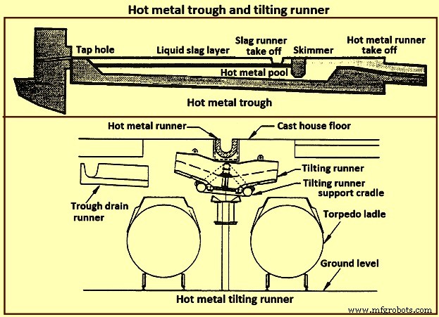
Fig 15 Hot metal trough and tilting runner
When maintenance of the trough lining is needed, the hot metal pool can be dumped by removing the hot metal dam, or by opening a trough drain gate, or by drilling into the side of the trough (at its lowest point) with a drain drill. The trough bottom is normally designed with a 2 % (minimum) slope for effective draining. Trough cross-section and length design are important for effective iron and slag flow pattern, retention, and separation. A good trough design results in hot metal yield improvements. Effective trough lining and cooling techniques are important for lining life, hot metal temperature, and cast house structural steel and concrete heat protection considerations. Troughs traditionally were contained in steel boxes ‘buried in sand’ in the cast house floor system. Improved trough design incorporates forced or natural air convection or water-cooling.
Cast house practice needs the runners to be as short as possible. This minimizes temperature loss of hot metal and reduces runner maintenance and flue generation. Shorter runners can also result in reduced capital expenditure for cast house building installation or modification. Since the runners are to slope away from the furnace, the cast house floor normally follows the same slope as the runners.
Slag runners are normally designed with a 7 % (minimum) slope. Slag can be directed to (i) slag pots for railway or mobile equipment haulage to a remote site for dumping, (ii) slag pits adjacent to the furnace for air cooling and water quenching prior to excavation by mobile equipment, and (iii) granulation facilities adjacent to the furnace for conversion of the liquid slag to granulated slag. Granulation units are provided with systems to eliminate flue emissions associated with environmental issues.
Hot metal runners are normally designed with a 3 % (minimum) slope. Hot metal is normally directed to hot metal transfer ladles (torpedo cars / open top ladles) for movement to the steel melting shop or pig casting machines. While normal practice used is to have one iron runner system with diverter gates directing the hot metal to different pouring positions, each with a ladle. Application of the tilting runner practice has been beneficial. A tilting runner is normally with an electrical motor-driven actuator (with a manual hand wheel back-up), and is tilted at around 5 degrees to divert the hot metal. A pool of hot metal is held in the tilting runner to minimize splashing and refractory wear. When one hot metal ladle has been filled, the runner is tilted to the opposite side to fill the other ladle. If needed, a locomotive removes the filled ladle and spots an empty ladle in its place. This operation can be done without plugging the furnace. When the tapping is finished, the tilting runner is tilted an additional 5 degrees to dump its pool of hot metal into the ladle.
Modern cast house design includes flat floors, where the runner is fully covered and is fitted flush with the floor. This allows safer and easier use of mobile vehicles in the cast house area. The use of radio controlled equipment and other devices have helped to reform cast house work, and these, along with effective emission control systems, have improved working conditions. As the BF hearth diameter is increased, there is a resulting need to increase the size of the cast-house. Large BF are normally designed with four tap holes (Fig 14). With a four top-hole configuration, the cast-house arrangement needs to provide sufficient space for movement around the floor itself. There is no design issues associated with this requirement as long as there is the necessary space provided in the site plan. Increasing the size of the cast-house in terms of floor plan does not represent a radical change in design philosophy which can pose a challenge the furnace designer. An efficient and strictly controlled tapping is necessary for ensuring a stable operation and high productivity of the BF.
Emission control
Fume collection requirements and applications appear to vary considerably around the globe. BFs presently have full, partial, or even no cast house fume collection system. Exhaust fan and bag house capacity of the order of 9,000 cubic meter per minute (cum/min) to 11,500 cum/min (depending upon operation and design practices) is typical for full flue capture of a two tap hole cast house installation (for trough runners and tilting runners).
Proper design and application of flue collection runner covers can facilitate cast house access (i.e. flat floor configuration using steel slabs or plates) for personnel and mobile equipment crossover. Runner covers can also reduce hot metal temperature loss and improve runner refractory longevity.
Some furnaces use flame suppression which eliminates the oxygen in the air directly over the trough and iron runners. Products of combustion prevent oxidation of the hot metal surface reducing visible particulate and flues.
Other aspects of BF design
It is necessary that complete study of every element in the process chain, from raw materials delivery to hot metal consumption is made to ensure that there are no ‘bottle necks’ in the system which can prevent the furnace from meeting the goals of its installation. While designing the BF, thought process is to be used to develop the furnace design and some alternatives are to be considered before freezing the design. During the designing of the furnace, those furnace equipments are to be selected which best meet the needs of the furnace operation.
The furnace design is to ensure (i) the furnace is capable of meeting the operational goals of production, productivity (tons per day per cubic metre of working volume), specific consumptions (kilograms per ton of hot metal), and product quality in cost effective manner, (ii) the furnace has the flexibility to accept and absorb the changes in the quality of the raw materials, and (iii) the furnace is capable of achieving the desired campaign life both with respect to time and the total production.
Financial justification is the over-riding consideration for the design. For this purpose, the economic study is to be very extensive. Further, the furnace design is to include latest technological developments so that the furnace does not become technologically outdated during its entire campaign.
The working volume of the furnace is the internal volume of the furnace calculated between the tuyeres and the stock line. Hearth productivity of the furnace is rated in tons per day per cubic metre of active hearth volume. Active hearth volume is the internal volume of the furnace calculated between the tuyeres and the tap hole. Active hearth volume is a measure of the holding capacity of the furnace for the liquids produced in the working volume (above the tuyeres). Hence, the tons per day per cubic metre of active hearth volume is a measure of the specific capacity (through-put per unit volume) of the hearth of the BF.
The design of the hearth is very important since it has a strong effect on the furnace operation. The furnace operation gets affected since the hearth liquid levels change rapidly which cause variations in gas flow pattern, gas utilization, and blast pressure. Also, because of these rapid changes in liquid level, there can be jamming / burning of the tuyeres which affect the blowing of the furnace.
The furnace hearth volume also determines the controls the operator is to exercise during furnace operation. For a very good hearth liquid level control, the high through-put furnace need around 90 % time spent in tapping. To make this time of tapping possible, cast floor is to be designed properly.
The furnace lining and cooling system needs special attention so that it does not pose any problem during the entire campaign of the BF. The selection of refractories, cooling elements, and internal furnace geometry is very important in this respect. Copper staves in this respect are expensive but they are very economical in comparison to the alternatives. Carbon lining of the hearth is very important for the long life of the hearth. The refractory lining thickness of the stack has implication on the furnace working volume.
The production needed normally determines the size of the BF. However, for the sizing of the BF, the raw materials, the product chemistry, and even operating philosophy are important. While the furnace size has implication on the capital cost, the productivity improvement has implication on the operating cost. The specific productivity of the furnace is to be determined for the determination of the size of the BF needed to produce the required quantity of hot metal. From the wide range of possible operating rates, the working volume of the furnace is to be calculated. Productivity and hence the furnace size is also to be based on the fuel rate. The fuel rate is dependent on the quality of raw materials, hot blast parameters, hot metal quality, and the operating philosophy.
The size is the most important factor for the determination of the BF productivity. However, there are other factors which also influence the BF productivity. The most important of these factors include (i) hot blast temperature and pressure, (ii) high top pressure, (iii) oxygen enrichment of the air blast, (iv) injection of auxiliary fuel at the tuyere, (v) prepared burden (sinter, pellets etc.), (vi) Fe content of the ferrous burden, (vii) ash in coke, (viii) quality of the coke, (ix) moisture content of the burden, (x) direct charging of fluxes (lime stone, dolomite etc.) in the BF, (xi) content of fines in the burden, (xii) quality of hot metal to be produced, (xiii) burden distribution control in the furnace, and (xiv) level of automation and control in the furnace.
The availability of furnace equipment, provision of stand-by equipment, and the maintenance philosophy are important factors which have high influence on the annual production from the BF. Further, incorporation of safe and healthy working practices during the operation of BF in the design of the BF is important which has a high influence on the furnace productions. In this regards, safety interlocks are to be provided at all the places where there exist a chance of unsafe operating practices to take place.
Processo de manufatura
- Escória de alto forno e seu papel na operação do forno
- Aspectos importantes do projeto de alto-forno e equipamentos auxiliares associados
- Sistema de automação, medição e controle de processos de alto forno
- Geração e uso de gás de alto-forno
- Produtividade do Alto Forno e os Parâmetros Influenciadores
- Operação de alto-forno e escória de alta alumina
- Sistema de resfriamento do alto-forno
- Casa de Fundição do Alto Forno e seu Funcionamento
- Alto-forno e seu projeto
- Fabricação de ferro por alto-forno e emissões de óxido de carbono