


Inclusões em aço fundido contínuo e sua detecção
Inclusões em aço fundido contínuo e sua detecção
O lingotamento contínuo de aço é um processo importante para a produção de aço em todo o mundo, devido às suas vantagens inerentes de economia de energia, alto rendimento, flexibilidade de operação e qualidade competitiva do produto fundido. Com o estabelecimento do lingotamento contínuo como principal via de produção do aço, a ênfase está sendo cada vez mais voltada para os aspectos de melhoria da qualidade e redução de custos da produção do aço através da tecnologia de lingotamento contínuo. Um dos requisitos de qualidade mais rigorosos atualmente é a limpeza do aço. A alta pureza do aço exige um controle rigoroso de inclusões não metálicas ou simplesmente inclusões durante o processo de lingotamento contínuo. Inclusões remanescentes no produto final podem danificar as propriedades do aço e degradar sua qualidade.
A remoção de inclusões no molde de lingotamento contínuo é difícil, pois o aço líquido torna-se sólido e as inclusões têm menos oportunidade de flutuar. A remoção de inclusões e a distribuição final de inclusões no produto de aço são altamente dependentes das propriedades das inclusões, transporte de inclusões no aço líquido e interação entre inclusões e casca solidificante. Assim, o entendimento do aprisionamento das inclusões e sua distribuição final no produto final são importantes para o controle da limpeza e da qualidade do produto siderúrgico.
O problema da qualidade superficial do aço laminado a quente e/ou a frio é sempre uma das preocupações importantes, pois está diretamente relacionado à qualidade do aço e ao preço. A qualidade superficial do aço laminado também é influenciada pela operação do processo de lingotamento contínuo e reaquecimento, uma vez que as inclusões são uma das principais causas de geração de trincas superficiais no aço laminado. Existem tentativas de melhorar a qualidade da superfície do aço modificando a composição e a morfologia das inclusões com base no cálculo termodinâmico. Mas essas tentativas parecem ainda não ser suficientes para resolver completamente o problema da qualidade da superfície.
A avaliação de inclusões em aço é de grande interesse e inclui (i) explorar a quantidade total, morfologia, distribuição de tamanho e distribuição espacial das inclusões, e (ii) identificar sua composição química.
As demandas cada vez maiores por produtos de aço de alta qualidade tornaram o pessoal siderúrgico cada vez mais consciente da necessidade de limpeza do aço. As inclusões são um problema importante no aço fundido que pode levar ao seu reparo excessivo ou rejeição. Vários defeitos no produto de aço laminado podem estar relacionados às inclusões. O comportamento mecânico do aço é controlado em grande parte pela fração de volume, tamanho, distribuição, composição e morfologia de inclusões e precipitados que atuam como geradores de tensão. A distribuição do tamanho das inclusões é particularmente importante, uma vez que macroinclusões grandes são as mais prejudiciais às propriedades mecânicas. Às vezes, um defeito catastrófico é causado por apenas uma única grande inclusão em um calor completo do aço. Embora as grandes inclusões sejam em número muito menor que as pequenas, sua fração de volume total pode ser grande.
A ductilidade é apreciavelmente diminuída pelo aumento das quantidades de inclusões de óxido ou sulfeto. Também a tenacidade à fratura diminui quando inclusões estão presentes em ligas de aço de baixa ductilidade de alta resistência. Degradação de propriedade semelhante de inclusões é observada em testes que refletem taxas de deformação lentas, rápidas ou cíclicas, como testes de fluência, impacto e fadiga. Além disso, as inclusões causam vazios, que podem induzir rachaduras. Grandes inclusões exógenas podem causar problemas na forma de superfície inferior, baixa polibilidade, resistência reduzida à corrosão e, em casos excepcionais, linhas de escória e laminações.
As inclusões também reduzem a resistência a 'trincas induzidas por hidrogênio' (HIC). A fonte da maioria dos problemas de fadiga no aço são óxidos duros e quebradiços, especialmente partículas grandes de alumina (Al2O3) com tamanho superior a 30 micrômetros. Embora a morfologia de solidificação das inclusões seja importante em aços fundidos, a morfologia das inclusões em produtos de aço forjado é amplamente controlada por seu comportamento mecânico durante o processamento do aço, ou seja, se são “duros” ou “macios” em relação à matriz de aço. O comportamento de diferentes tipos de inclusões com sua deformação durante a laminação é mostrado esquematicamente na Fig 1.
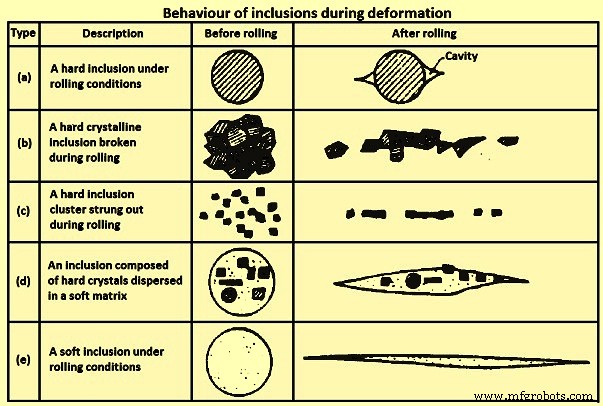
Fig 1 Comportamento das inclusões durante a deformação
A formação de 'Stringer', tipo (b) e (c) na Fig 1, aumenta a direcionalidade das propriedades mecânicas, afetando adversamente a tenacidade e a ductilidade em particular. As piores inclusões para tenacidade e ductilidade, particularmente nas propriedades de direção de espessura do produto laminado plano, são aquelas que se deformam com a matriz, como (d) na Fig 1. Para evitar esses problemas, o tamanho e a frequência das inclusões prejudiciais devem ser cuidadosamente controlados. Especialmente nenhuma inclusão deve estar presente no aço fundido acima de um tamanho crítico.
A caracterização das inclusões é um dos aspectos mais importantes para garantir um aço limpo. As inclusões são um tipo de defeito presente no aço que afeta severamente as propriedades como polibilidade, ductilidade e resistência à fadiga do aço. Assim, as inclusões devem ser controladas para a produção de aço de alto desempenho. As inclusões primárias são formadas durante os tratamentos de aço na panela. A maioria destes é removida para a escória da panela ou no revestimento. No entanto, o restante das inclusões ainda precisa ser removido através das sucessivas etapas do processo e, adicionalmente, novas inclusões são formadas durante a fundição e a solidificação.
Devido ao número decrescente de inclusões com o aumento do tamanho, os diferentes intervalos de tamanho apresentam problemas diferentes. Com relação à polibilidade, o grande número de pequenas inclusões é mais prejudicial do que as inclusões grandes, mas simultaneamente mais raras, simplesmente por serem mais frequentes. Por outro lado, em baixos níveis de tensão, trincas críticas, que podem levar à falha durante a vida útil de um produto de aço, provavelmente crescem nas inclusões muito grandes. Essas inclusões são raras e é difícil estimar corretamente sua densidade de ocorrência. Em níveis intermediários de tensão de fadiga, inclusões de tamanhos médios competem com defeitos superficiais como pontos de iniciação de trincas.
Inclusões em aço podem se formar endogenamente (indígenas) ou exogenamente. As inclusões endógenas são o resultado de elementos de liga dentro do aço reagindo com gás dissolvido (como oxigênio) para formar inclusões sólidas no aço fundido. A inclusão pode ser formada durante a desoxidação, reoxidação ou solidificação da solubilidade de espécies de gás reduzidas no estado sólido. As inclusões exógenas vêm de fontes externas ao aço líquido, como arrastamento de escória ou danos refratários.
Inclusões endógenas
Inclusões endógenas são produtos de desoxidação ou inclusões precipitadas durante o resfriamento e solidificação do aço.
Produtos de desoxidação – Inclusões de alumina em aço morto com alumínio de baixo carbono (LCAK) e inclusões de sílica (SiO2) em aço morto com silício, que são geradas pela reação entre o oxigênio dissolvido e os desoxidantes de alumínio e silício adicionados, são inclusões de desoxidação típicas. As inclusões de alumina são dendríticas quando formadas em um ambiente com alto teor de oxigênio. As inclusões de alumina do tipo cluster por desoxidação ou reoxidação são típicas de aços mortos com alumínio. As inclusões de alumina formam facilmente aglomerados tridimensionais por meio de colisão e agregação devido à sua alta energia interfacial. As inclusões individuais no aglomerado podem ter de 1 micrômetro a 5 micrômetros de diâmetro. Antes da colisão, separação ou agregação com outras partículas, elas podem ter a forma de placa de flores ou inclusões poliédricas (agregadas). Alternativamente, acredita-se que inclusões de alumina semelhantes a corais resultem do “maturamento de Ostwald” de inclusões de alumina originalmente dendríticas ou agrupadas. As inclusões de sílica são normalmente esféricas devido ao estado líquido ou vítreo no aço líquido. A sílica também pode se aglomerar em aglomerados.
Inclusões precipitadas – Essas inclusões se formam durante o resfriamento e a solidificação do aço. Durante o resfriamento, a concentração de oxigênio/nitrogênio/enxofre dissolvido no líquido aumenta enquanto a solubilidade desses elementos diminui. Assim, inclusões como alumina, sílica, nitreto de alumínio (AlN) e sulfeto precipitam. Os sulfetos se formam interdendricamente durante a solidificação e frequentemente nucleam em óxidos já presentes no aço líquido. Essas inclusões são normalmente pequenas (menos de 10 micrômetros de tamanho).
Inclusões exógenas
As inclusões exógenas surgem principalmente da interação química acidental (reoxidação) e mecânica do aço líquido com seu entorno (arrastamento de escória e erosão do revestimento refratário). Durante a usinagem, eles produzem trepidação, causando pites e goivagens na superfície das seções usinadas, quebras frequentes, bem como desgaste excessivo da ferramenta.
As inclusões exógenas estão sempre relacionadas à prática e seu tamanho e composição química frequentemente levam à identificação de suas fontes, sendo suas fontes principalmente reoxidação, arrastamento de escória, erosão do revestimento e reações químicas. Essas inclusões têm as seguintes características.
Tamanho grande – As inclusões exógenas da erosão refratária são normalmente maiores do que as do arrastamento de escória.
Composição composta/natureza multifásica – As inclusões exógenas são causadas pelos fenômenos a saber (i) devido à reação entre o aço líquido e a sílica, FeO e MnO na escória e o refratário de revestimento com as inclusões de alumina geradas podem permanecer em sua superfície, (ii) à medida que as inclusões exógenas se movem , devido ao seu grande tamanho, eles podem aprisionar inclusões de desoxidação como alumina em sua superfície, (iii) inclusões exógenas atuam como núcleos heterogêneos para precipitação de novas inclusões durante seu movimento em aço líquido, e (iv) inclusões de escória ou reoxidação podem reagir com os refratários de revestimento ou desalojar mais material no aço líquido.
Forma – As inclusões exógenas normalmente têm forma irregular, se não esférica por arraste de escória ou sílica do produto desoxidante. As inclusões exógenas esféricas são normalmente grandes (maiores que 50 micrômetros) e principalmente multifásicas, mas as inclusões esféricas de desoxidação são normalmente pequenas e monofásicas.
Quantidade – As inclusões exógenas são pequenas em número em comparação com as pequenas inclusões.
Distribuição – As inclusões exógenas têm distribuição esporádica no aço e não são bem dispersas como pequenas inclusões. Uma vez que normalmente são aprisionados no aço durante o fervilhamento e a solidificação, sua incidência é acidental e esporádica. Por outro lado, eles flutuam facilmente, portanto, concentram-se apenas em regiões da seção de aço que solidificam mais rapidamente ou em zonas das quais sua fuga por flotação é de alguma forma dificultada. Assim, essas inclusões são freqüentemente encontradas perto da superfície.
Efeito nas propriedades do aço – As inclusões exógenas são mais deletérias às propriedades do aço do que as pequenas inclusões devido ao seu grande tamanho.
Uma questão que substitui a fonte das inclusões exógenas é por que essas inclusões grandes não flutuam rapidamente quando estão no aço. As possíveis razões podem ser (i) formação tardia durante a fabricação do aço, transferência ou erosão nos vasos metalúrgicos, deixando tempo insuficiente para que eles subam antes de entrar no molde da máquina de lingotamento, (ii) falta de superaquecimento suficiente, (iii) fluxo de fluido durante a solidificação induz aprisionamento de escória de molde, ou (iv) re-arrastamento de inclusões flutuadas antes que elas entrem totalmente na escória.
Inclusões exógenas de reoxidação – A forma mais comum de grandes macroinclusões por reoxidação encontrada no aço é o aglomerado de alumina. O ar é a fonte mais comum de reoxidação, que pode ocorrer (i) o aço líquido no tundish se mistura com o ar de sua superfície superior no início do vazamento devido à forte turbulência e os filmes de óxido na superfície do líquido que flui são dobrados no líquido, formando planos fracos de partículas de óxido, (ii) o ar é sugado para dentro do aço líquido nas juntas entre a panela e o distribuidor, e entre o distribuidor e o molde, e (iii) o ar penetra no aço a partir do superfície superior do aço na panela, distribuidor e molde durante o vazamento.
Durante este tipo de reoxidação, elementos desoxidantes, como alumínio, cálcio, silício, etc. são preferencialmente oxidados e seus produtos se desenvolvem em inclusões, normalmente de uma a duas magnitudes maiores que as inclusões de desoxidação. A solução para evitar esse tipo de reoxidação é limitar a exposição do ar ao processo de fundição. Isso pode ser feito (i) encobrindo com cortina de gás inerte utilizando um coletor de anel de aço ou anel refratário poroso ao redor das conexões entre a panela e o distribuidor e entre o distribuidor e o molde, (ii) purgando algum gás argônio no tundish antes do vazamento e na superfície do tundish durante o vazamento e (iii) controlando a injeção de gás argônio na panela para evitar a formação de olhos.
Outra fonte de reoxidação está nas escórias e refratários de revestimento. Por esse mecanismo de reoxidação, as inclusões dentro do aço crescem à medida que se aproximam da interface da escória ou revestimento através da reação SiO2 / FeO / MnO + [Al] =[Si] / [Fe] / [Mn] + Al2O3. Isso leva a inclusões de alumina maiores com composição variável. Esse fenômeno afeta ainda mais as inclusões exógenas de diferentes maneiras, a saber:(i) essa reação pode erodir e desigual a superfície do revestimento, o que altera o padrão de fluxo do fluido próximo às paredes do revestimento e pode induzir uma ruptura ainda mais acelerada do revestimento, e (ii) um grande inclusão exógena de revestimento quebrado ou escória arrastada pode aprisionar pequenas inclusões, como produtos de desoxidação, e também atuar como um núcleo heterogêneo para novos precipitados, o que complica a composição de inclusões exógenas.
Para evitar a reoxidação da escória e do revestimento refratário, é muito importante manter um baixo teor de SiO2, FeO e MnO. Tem sido relatado que tijolos com alto teor de alumina ou zircônia contendo baixos níveis de sílica livre são mais apropriados para uso.
Inclusões exógenas de arrastamento de escória – Qualquer operação siderúrgica ou transferência de aço líquido envolve mistura turbulenta de escória e metal, especialmente durante a transferência entre vasos. Isso produz partículas de escória suspensas no aço. As inclusões de escória, de 10 micrômetros a 300 micrômetros de tamanho, contêm grandes quantidades de CaO(cal) ou MgO (magnésia), e são normalmente líquidas na temperatura do aço líquido e, portanto, têm forma esférica. O uso de um distribuidor em forma de “H” e despejá-lo através de duas conchas diminui o arrastamento de escória durante o período de troca de concha. As causas que afetam o arrastamento da escória no aço líquido durante o processo de lingotamento contínuo incluem (i) durante as operações de transferência da panela para o distribuidor e do distribuidor para o molde, especialmente para vazamento aberto, vórtice na superfície superior do aço líquido que no nível baixo do aço líquido pode ser evitado de várias maneiras, como interromper o vazamento antes do início do vórtice, (ii) emulsificação e arrastamento de escória na superfície superior, especialmente sob agitação de gás acima de uma vazão crítica de gás, (iii) turbulência no menisco no molde e (iv) propriedades da escória, como tensão interfacial e viscosidade da escória.
Como exemplo, pó de molde pode ser aprisionado no aço líquido devido a (i) turbulência no menisco (Fig 2A), (ii) vórtice (Fig 2C), (iii) emulsificação induzida por bolhas que se movem do aço para a escória [Fig 2B e 2D), (iv) sucção ao longo da parede do bocal devido à diferença de pressão (2E), (v) fluxo de alta velocidade que corta a escória da superfície (2A) e (vi) flutuação de nível (Fig 2B) .
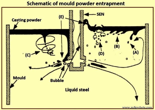
Fig 2 Esquema de aprisionamento de pó de molde
A tensão interfacial entre o aço e o pó de fundição líquido determina a altura do menisco de aço e a facilidade de arrastamento do fluxo. Especificamente, uma tensão interfacial de 1,4 newtons por metro (N/m) para uma escória de cal-sílica-alumina em contato com ferro puro produz uma altura de menisco de cerca de 8 mm. A tensão interfacial é reduzida a um valor baixo por espécies tensoativas como o enxofre ou por uma reação de troca interfacial como a oxidação do alumínio no aço pelo óxido de ferro na escória. A baixíssima tensão interfacial associada a uma reação química pode proporcionar turbulência espontânea na interface, através do efeito Marangoni. Tal turbulência pode criar uma emulsão na interface, criando esferas indesejáveis de escória no aço.
Inclusões exógenas da erosão/corrosão do revestimento refratário – A erosão de refratários, que inclui areia de bloco de poço, sujeira solta, tijolos refratários quebrados e partículas de revestimento cerâmico, é uma fonte muito comum de grandes inclusões exógenas que são tipicamente sólidas e relacionadas aos próprios materiais da panela e do distribuidor. Estes são normalmente materiais grandes e de formato irregular. Inclusões exógenas podem atuar como locais para nucleação heterogênea de alumina, ou agregar com outras inclusões indígenas. A ocorrência de produtos de erosão refratária ou inclusões introduzidas mecanicamente podem prejudicar completamente a qualidade do aço de outra forma muito limpo.
Em alguns estudos para investigar o processo de erosão, foi relatado que os 'refratários vitrificados' e as 'camadas de reação na superfície dos tijolos' são formados com aço líquido a 1.550 graus C a 1.600 graus C. Os entupimentos de grande inclusão no superfície do revestimento também pode ser liberada no aço líquido.
A erosão do revestimento normalmente ocorre em áreas de fluxo turbulento, especialmente quando combinada com reoxidação, altas temperaturas de vazamento e reações químicas. Os parâmetros que afetam fortemente a erosão do revestimento são descritos abaixo.
Alguns tipos de aço são bastante corrosivos (como o alto teor de manganês e os que são mal mortos e têm alto teor de oxigênio solúvel) e atacam os tijolos de revestimento.
Reações de reoxidação, como as que o alumínio dissolvido no aço líquido reduz a sílica no refratário do revestimento, gerando inclusões à base de óxido de ferro que são muito reativas e molham os materiais do revestimento, levando à erosão do refratário do revestimento em áreas de alta turbulência do fluido.
A composição e a qualidade do tijolo têm um efeito considerável na qualidade do aço. Em uma das plantas, três tipos de materiais (alta alumina, Al2O3-SiC-C e MgO-C com taxa de desgaste de 1 mm/calor, 0,34 mm/calor, 0,16 mm/calor, respectivamente) foram adotados no linha de escória, onde o refratário tende a ser danificado por fluxo escória e escória tundish, e o tijolo MgO-C apresenta a maior durabilidade entre os três. O óxido de manganês ataca preferencialmente as porções contendo sílica do refratário. Grãos de alumina e zircônia de altíssima pureza podem resistir ao ataque do óxido de manganês.
A erosão refratária rápida de aços com alto teor de manganês pode ser restringida pelo (i) uso de refratários de alumina ou zircônia de pureza muito alta, (ii) minimizando o oxigênio matando completamente o aço com um desoxidante forte, como alumínio ou cálcio, e evitando a absorção de ar. Os revestimentos tundish à base de sílica são piores do que os revestimentos pulverizados à base de magnésia. Os refratários de alta alumina estão sendo sugeridos como os mais promissores. A incorporação de óxido de cálcio no refratário do bocal pode ajudar liquefazendo as inclusões de alumina na parede, desde que a difusão de CaO para a interface seja rápida o suficiente e a erosão do bocal não seja um problema. A erosão do bocal pode ser combatida controlando a composição refratária do bocal (por exemplo, evitando impurezas de sódio, potássio e silício) ou revestindo as paredes do bocal com alumina pura, nitreto de boro ou outro material resistente. O refratário na superfície das paredes da blindagem deve ser escolhido para minimizar as reações com o aço que criam inclusões e entupimentos.
A velocidade excessiva do aço líquido afeta a erosão do revestimento ao longo das paredes do distribuidor, como a zona de entrada. Uma almofada pode ser usada para evitar a erosão do fundo do distribuidor, bem como controlar o padrão de fluxo. Tem sido sugerido que velocidades de aço líquido acima de 1 metro por segundo são perigosas em relação à erosão.
O contato excessivo ou o tempo de enchimento e a alta temperatura deterioram os problemas de erosão. Durante um longo período de retenção na panela, as inclusões maiores podem flutuar na escória da panela. No entanto, quanto mais tempo o aço estiver em contato com o revestimento da panela, maior será a tendência dos produtos de erosão da panela. As soluções são baseadas no desenvolvimento de refratários altamente estáveis para um determinado grau de aço, desenvolvendo insertos refratários densos e resistentes ao desgaste para áreas de alto fluxo e evitando a reoxidação.
Inclusões exógenas de reações químicas – As reações químicas produzem óxidos da modificação da inclusão quando o tratamento com cálcio é realizado de forma inadequada. Identificar a origem dessas inclusões nem sempre é fácil, pois, por exemplo, inclusões contendo óxido de cálcio também podem ser originadas de escórias arrastadas.
Aglomeração e obstrução de inclusão – A aglomeração de inclusões sólidas pode ocorrer em qualquer superfície auxiliada por efeitos de tensão superficial, inclusive em superfícies refratárias e bolhas. O alto ângulo de contato da alumina no aço líquido (134 graus a 146 graus) incentiva uma inclusão para se fixar ao refratário para minimizar o contato com o aço. Altas temperaturas de 1.530 graus C permitem a sinterização da alumina. Grande ângulo de contato e maior tamanho de inclusão favorecem a aglomeração de inclusões. Devido à colisão e aglomeração, as inclusões no aço tendem a crescer com o aumento do tempo e da temperatura. O crescimento de inclusão por colisão, aglomeração e coagulação em lingotes tem sido objeto de vários estudos, nos quais é relatada a simulação numérica de nucleação de inclusão a partir da adição de desoxidante e crescimento por colisão e difusão de nano-tamanho para micro-tamanho.
Os fundamentos da sinterização de alumina em aglomerados precisam de mais investigação, embora alguns estudos tenham usado a teoria fractal para descrever a morfologia do aglomerado (características). O exemplo mais óbvio de aglomeração de inclusão na superfície dos refratários de revestimento é o entupimento do bocal durante o lingotamento contínuo de aço líquido.
Efeito do fluxo de fluido e solidificação nas inclusões – A distribuição de inclusão no lingotamento contínuo de aço é afetada pelo fluxo de fluido, transferência de calor e solidificação do aço líquido. Um índice popular para aprisionamento de inclusão é a velocidade crítica de avanço da frente de solidificação, que é afetada por vários parâmetros, como forma de inclusão, densidade, energia superficial, condutividade térmica, taxa de resfriamento (taxa de solidificação) e condições salientes da frente de solidificação. Foi relatado que o aprisionamento é controlado por forças de arrasto e interfaciais (força de Van der Waals). Tem sido sugerido que quanto mais rápida é a taxa de solidificação, maior é a probabilidade de aprisionamento. A probabilidade de aprisionamento diminui com o aumento do tempo de solidificação, menor segregação, saliências menores na frente de solidificação. Os espaçamentos dos braços dendritos têm grande efeito no aprisionamento de inclusões e estão relacionados aos fenômenos de empurrão, engolfamento; ou aprisionamento.
Operações de fundição contínua, inclusões e aço limpo
As operações de lingotamento contínuo controlam a limpeza do aço. Um estudo sistemático de remoção de inclusões descobriu que o tratamento com panela reduz as inclusões em cerca de 65% a 75%, o distribuidor remove as inclusões em cerca de 20% a 25%, embora a reoxidação às vezes tenha ocorrido e o molde remove as inclusões em cerca de 5% a 10%. A operação do distribuidor tem um grande efeito na limpeza do aço. Os fatores importantes nas operações de tundish que afetam a limpeza do aço são a profundidade e capacidade do tundish, transições de fundição, refratário de revestimento do tundish, fluxo do tundish, agitação do gás argônio e controle de fluxo do tundish.
Principais escórias – As escórias superiores na panela e no distribuidor fornecem várias funções, como (i) isolamento do aço líquido tanto termicamente (para evitar perda excessiva de calor) quanto quimicamente (para evitar a entrada de ar e reoxidação) e (ii) absorção das inclusões para fornecer refino de aço adicional. Um fundente comum é a casca de arroz queimada, que é barata, um bom isolante e oferece boa cobertura sem crostas. No entanto, a casca de arroz é rica em sílica (cerca de 80% SiO2), que pode ser reduzida para formar uma fonte de inclusões. Eles também são muito empoeirados e com seu alto teor de carbono (cerca de 10 % C), podem causar contaminação do aço de ultra baixo carbono.
Fluxos básicos (baseados em CaO-Al2O3-SiO2 e sílica inferior a 10%) são teoricamente muito melhores do que casca de arroz durante o refino de aços LCAK e foram correlacionados com menor oxigênio no distribuidor. Por exemplo, em um estudo, o oxigênio total diminuiu da faixa de 25 ppm (partes por milhão) e 50 ppm para a faixa de 19 ppm e 35 ppm com a basicidade do fluxo aumentando de 0,83 para 11. Em um dos a usina siderúrgica, o uso de fluxos básicos, o oxigênio total no molde foi relatado como sendo menor e o defeito do produto de aço diminuiu. No entanto, é mais provável que o fluxo básico seja ineficaz, pois forma facilmente uma crosta na superfície, devido à sua taxa de fusão mais rápida e alta temperatura de cristalização. Essa crosta resulta na evolução de um olho aberto sem escória ao redor da cobertura da panela durante o fervilhamento, o que não apenas fornece uma área excessiva para reoxidação, mas também permite uma perda significativa de calor por radiação e desconforto para os operadores na plataforma de trabalho. Além disso, os fluxos básicos normalmente têm viscosidade mais baixa. Assim, eles são mais facilmente arrastados. Para evitar esses problemas, uma usina siderúrgica usou um fluxo de duas camadas, com um fluxo básico de baixo ponto de fusão na parte inferior para absorver as inclusões e uma camada superior de fluxo à base de casca de arroz para fornecer isolamento. Isso baixou o oxigênio total de 22,5 ppm para 16,5 ppm.
Dispositivos de controle de profundidade, capacidade e fluxo do distribuidor – O padrão de fluxo do distribuidor deve ser projetado para aumentar o tempo de residência do aço líquido, evitar “curto-circuito” e promover a remoção de inclusões. O fluxo do distribuidor é controlado por sua geometria, nível, design de entrada (revestimento) e dispositivos de controle de fluxo, como almofadas de impacto, açudes, barragens, defletores e filtros. O distribuidor profundo com grande capacidade aumenta o tempo de residência do aço líquido e das partículas e, portanto, estimula a remoção de inclusões. O tundish profundo também desencoraja a formação de vórtices, permitindo mais tempo para transições de panela antes que o arrastamento de escória se torne um problema. O tamanho do distribuidor para o aço LCAK aumentou gradualmente em todo o mundo nos últimos 20 anos, normalmente atingindo 60 toneladas a 80 toneladas com cerca de 1,8 metros de profundidade no caso de uma máquina de lingotamento contínuo de placas.
Se alinhado corretamente, e talvez junto com o(s) açude(s) e represa(s), uma almofada de derramamento pode melhorar a limpeza do aço, especialmente durante as trocas de panelas. Como exemplo, adicionar a almofada de despejo em uma das siderúrgicas diminuiu a alumina durante as transições da panela de 48 ppm para 15 ppm. Em outra siderúrgica, o oxigênio total diminuiu de 26 ppm (com uma almofada de cúpula) para 22 ppm (com uma almofada de calota). Em mais uma siderúrgica, a limpeza do aço melhorou ao colocar 77 furos em sua barragem, fazendo com que ela atue como um filtro parcial. Em uma outra usina siderúrgica, uma técnica semelhante que consiste em defletores combinados com uma cobertura inicial do distribuidor baixou a média de oxigênio total no distribuidor durante a fundição em estado estacionário de 39 +/- 8 ppm para 24 +/- 5 ppm.
Os filtros cerâmicos e o filtro CaO são muito eficazes na remoção de inclusões. No entanto, seu custo e tempo de operação efetivo antes do entupimento normalmente tornam seu uso proibitivo. A injeção de gás inerte no tundish a partir de seu fundo melhora a mistura do aço líquido e promove a colisão e remoção de inclusões. Em uma das siderúrgicas, ao aplicar esta tecnologia, o oxigênio total foi reduzido com sucesso para 16 ppm no distribuidor. No entanto, o perigo desta tecnologia é que quaisquer bolhas carregadas de inclusões que escapem do distribuidor e fiquem presas no cordão causem defeitos graves. Foi relatado que a fração de área de óxido (0,001%) do aço no distribuidor diminui 25% por esta técnica em comparação com aqueles sem esta técnica.
Transições de transmissão – As transições de lingotamento ocorrem no início de uma sequência de lingotamento, durante as trocas de panelas e trocas de bicos e no final do lingotamento. Essas transições são responsáveis pela maioria dos defeitos de limpeza. As inclusões são frequentemente geradas durante as transições e podem persistir por muito tempo, contaminando assim muito aço. O índice de defeitos da fita no início da primeira bateria foi 5 vezes maior do que no meio da primeira bateria e mais de 15 vezes maior do que nas baterias sucessivas. Durante esses períodos instáveis de fundição, o arrastamento de escória e a absorção de ar são mais prováveis de ocorrer, o que induz problemas de reoxidação. Uma concha de 'auto-abertura' abre sozinha sem ter que lancetar o bico. A punção requer a remoção da cobertura e isso permite que a reoxidação ocorra, especialmente durante os primeiros 650 mm a 1.200 mm da fundição. Caldeiras com abertura lancetada têm níveis totais de oxigênio que são cerca de 10 ppm mais altos que os aquecimentos com abertura automática. A embalagem cuidadosa da areia de abertura da panela ajuda a conseguir a auto-abertura da panela. A areia da concha também é uma fonte de reoxidação devido ao alto teor de sílica.
Uma melhoria durante as transições da panela é interromper o fluxo de líquido para dentro do molde até que o distribuidor esteja cheio e borbulhar gás através da rolha para promover a flotação de inclusão. Outra melhoria é a abertura de novas conchas com cobertura submersa. Com esta medida, o oxigênio total diminuiu em uma das siderúrgicas de 41 +/- 14 ppm para 31 +/- 16 ppm com qualidade mais consistente em toda a sequência.
Como exemplo, em uma das siderúrgicas, o oxigênio total no distribuidor durante as transições é de 50 ppm a 70 ppm, comparado com apenas 25 ppm a 50 ppm no estado estacionário. Em outras siderúrgicas, a diferença é de apenas 3 ppm. One of the steel plants has reported transitions to have total oxygen only 19.2 ppm relative to 16 ppm at steady state while another steel plant has reported total oxygen of 27 +/- 5 ppm during transitions and 24 +/- 5 ppm during steady casting. At one other steel plant, the nitrogen pickup in tundish is 5 ppm to 12 ppm during the start period of the teeming which decreases to 0 ppm to 2 ppm after around 12 minute of teeming (steady casting state).
Near the end of the teeming of a ladle, ladle slag can enter the tundish, due to the vortex formed in the liquid steel near the ladle exit. This phenomenon needs some steel to be kept in the ladle upon closing (e.g. a four ton of ‘heel’). In addition, the tundish depth drops after ladle close, which disrupts normal tundish flow and can produce slag vortexing, slag entrainment, and increased total oxygen in the mould.
Shrouding, argon protection, and sealing – Steel shrouding from ladle to the mould includes ladle slide gate shrouding, ladle collector nozzle, ladle shroud connection, tundish well block, and top plate of the tundish slide gate. Shroud design variations are of great importance in the operations of the tundish-to-mould transfer of liquid steel. Use of an optimized shrouding system greatly lowers reoxidation during transfer operations. For example, use of a ladle shroud has lowered nitrogen pickup from 24 ppm to 3 ppm relative to open pouring at one of the steel plant. In another steel plant, replacing the tundish pour box with a ladle shroud and dams has lowered nitrogen pickup (ladle to tundish) from 7.5 ppm to 4 ppm, and also has lowered slag entrainment during transitions. At one other steel plant, improving the shroud system from ladle to tundish has lowered the nitrogen pickup from 14 ppm to 3 ppm.
Shrouding the ladle to tundish stream at one of the steel plants has lowered the dissolved aluminum loss from 130 ppm to 70 ppm and has lowered the total oxygen increase by 12 ppm. When pouring without shrouds, which is common in billet casting, the turbulence of the casting stream is very important. A smooth stream entrains much less oxygen than a turbulent or ‘ropy’ stream. For the production of a smooth stream between the tundish and the mould in these operations, the metering nozzle edges are to be maintained and high speed flow in the tundish across the nozzles is to be avoided. A protective tundish cover with carefully sealed edges also helps in lowering total oxygen from 41.5 ppm to 38 ppm.
A variety of inert gas shrouding systems is now available. Total oxygen in the cast product (LCAK steel) can be lowered from 48.5 ppm to 28.5 ppm by shrouding between the ladle and the tundish, and to 23 ppm by this shrouding plus argon sealing. It is very important to carefully seal the joints in the shrouds, both to improve cleanliness and to prevent clogging. Improving the bayonet system between the ladle nozzle and ladle shroud, lowers the nitrogen pickup there from 8 ppm to less than 1 ppm. Stiffening the submerged entry nozzle (SEN) holder and increasing its maintenance has lowered the initial nitrogen pickup from 1.8 ppm to 0.3 ppm in one of the steel plants.
Inert gas can protect the steel from air reoxidation in several ways. To combat air entrainment at the beginning of a cast, the tundish can be purged with inert gas (to displace the air) prior to ladle opening, which lowers both the total oxygen and the nitrogen pickup during startup. Argon injection to pressurize the shrouds can help to prevent the liquid steel from air reoxidation through any joints or leaks. Guidelines for minimum argon gas flow to ensure positive pressure inside the nozzle are to be made. In addition, flooding the joints with argon gas ensures that any leaks aspirate inert gas and not air.
Injecting argon into the tundish stopper rod and improved sealing at one steel plant has decreased nitrogen pickup from tundish to cast product from 5 ppm to 1.8 ppm, has lowered total oxygen in the cast product from 31 ppm to 22 ppm, has decreased the size of alumina clusters in the cast product, and has decreased clogging. Elsewhere, argon injection through the stopper rod lowered the number of inclusions detected by the Mannesmann inclusion detection by analysis surfboards (MIDAS) method by 25 % to 80 %. Injection of argon gas purge through upper plate of the sliding gate has lowered the quantity of 50 micrometers to 100 micrometers sized inclusions from 3 per square centimeter to 0.6 per square centimeter, and lowered 100 micrometers to 200 micrometers macro-inclusions from 1.4 per square centimeter to 0.4 per square centimeter.
Clogging and new techniques at SEN – The nozzle is one of the few control parameters which is relatively inexpensive to change, yet has a profound influence on the flow pattern and hence on the quality of the cast product. Nozzle parameters include bore size, port angle and opening size, nozzle wall thickness, port shape (round, square, or oval), number of ports (bifurcated or multiport), nozzle bottom design (well, flat , or sloped), and submergence depth. Both too large and too small submergence depth increases problems with longitudinal cracks and transverse depressions.
One of the studies has found the occurrence of corundum (Al2O3) covering the bore surface of nozzles used to pour aluminum killed steel ingot early in 1949. Another study has found that nozzle blockage occurred with high levels aluminum (0.0036 %) and that nozzle sectioning revealed dendritic growth of alumina from the nozzle wall onto the bore. Yet another study has observed clogs of aluminum, zircon, titanium, and the rare earths.
Nozzle clogs are caused by reoxidation, or by the accumulation of solid oxides or sulphides, such as alumina and calcium sulphide (CaS) in the steel. In addition to interfering with the production process, tundish nozzle / SEN clogging is detrimental to steel cleanliness for several reasons such as (i) dislodged clogs either become trapped in the steel, or they change the flux composition, leading to defects in either case, (ii) clogs change the nozzle flow pattern and jet characteristics leaving the nozzle, which disrupt flow in the mould, leading to slag entrainment and surface defects, and (iii) clogging interferes with mould level control, as the flow control device (stopper rod or slide gate) tries to compensate for the clog.
The cure for the nozzle clog problem includes improving steel cleanliness by improving ladle practices, implementing smooth and non-reacting refractories, and controlling fluid flow though the nozzle for ensuring a smooth flow pattern. Changing from a three-plate slide gate system to a stopper rod system has reduced clogging at one of the steel plant. Several practices can be used to minimize clogging. In addition to taking general measures to minimize inclusions, clogging through refractory erosion can be countered by controlling nozzle refractory composition, (e.g. avoiding sodium, potassium, and silicon impurities), or coating the nozzle walls with pure alumina, boron nitride, or other resistant material. There are several new techniques at SEN which have reported to improve the fluid flow pattern and inclusion removal, such as (i) swirl-nozzle technique, (ii) step nozzle technique, (iii) multi-ports nozzle, and (iv) oval offset bore throttle plate.
Swirl-nozzle technique – A fixed blade placed at the upstream end of the SEN induces a swirl flow in nozzle. Centrifugal force generated by the swirling flow in the nozzle can distribute the liquid steel equally to its two spouts. Since liquid steel stream with centrifugal force has the maximum velocity in the vicinity of the wall inside the nozzle, it tends to flow out of the upper part of the spout. Hence, the velocity distribution which tends to have higher values toward the lower part of the spout with a conventional nozzle can become uniform. It has been reported that by using this swirl nozzle for the continuous casting, the defect ratio of finish products (coils) has decreases to 25 % of the conventional nozzles, and casting speed has riseby 30 %. Its cost is higher only by 20 % than the cost of the conventional and hence it is cheaper than using an ‘electro-magnetic brake’. This swirl flow pattern can also be generated by the ‘electro-magnetic stirring’ at the nozzle, which can also improve the solidification structure of the cast steel as well.
Step nozzle – The flow pattern at out-ports of conventional SEN is uneven or biased because of the sliding gate of SEN. This biased flow pattern (swirl flow at out-ports of SEN) increases the impingement of the jet, and hence worsens inclusion removal to top surface. By using inner annular steps, the biased flow in mould can be weakened. The calculation suggests that the removal fraction of 50 micrometers inclusions to the top surface of the mould is 2 % with the conventional SEN, but increases to 7 % with the use of the stepped SEN.
Oval offset bore throttle plate – In the conventional system, gate throttling results in a highly skewed and biased flow in the tundish-to-mould flow channel both upstream and downstream of the gate. These effects have considerably diminished the offset bore system. The offset gate design extracts the fluid more centrally from the tundish well nozzle. Hence, the system is less sensitive to any build-up on the walls of the well nozzle, which extends the useful life of the tundish well nozzle and hence, allowing longer tundish sequences. In practice, it has also been found that clogging within the plates of the offset bore gate is considerably reduced as compared to the conventional gate.
Multiple out-ports – It is well known that the surface velocity of the mould has a big effect on slag entrainment and top surface fluctuation. Several defects are related to the surface velocity of the mould. Thus decreasing the surface velocity is very important to improve the steel cleanliness. This task can be targeted by using multiple out-ports at SEN. Addition of a bottom hole at SEN lowers the momentum of the side jets so it is possible to get a good steel flow and meniscus condition even under high throughput which is better stabilized.
Mould and operation of continuous casting machine
The continuous casting mould region is the last refining step where inclusions either are safely removed into the top slag layer or they become entrapped into the solidifying shell to form permanent defects in the steel product. Mcpherson has used the words ‘mould metallurgy’ in 1985 to emphasize the importance of the mould to improve steel cleanliness. The mould flow pattern is very important for avoiding defects since it affects particle transport and removal to the top slag or entrapment by the solidifying shell.
Top surface control – Directing too much flow towards the top surface generates surface defects, due to transients, turbulence at the meniscus, and inclusion problems from slag entrainment. However, decreasing surface flows too much can also generate problems. These include surface defects due to the meniscus region becoming too stagnant, and a higher fraction of incoming inclusion particles being sent deep before they can be removed into the slag. Hence, a balance is to be found in order to optimize the flow parameters to avoid defects.
The most obvious source of surface defects is the capture of foreign particles into the solidifying shell at the meniscus. If the steel jet is directed too deep or has too little superheat, then the liquid surface has very little motion and becomes too cold. This can lead to freezing of the steel meniscus, which aggravates the formation of meniscus hooks. This allows inclusions and bubbles to be captured, the latter forming pinholes just beneath the surface of the cast product. As an example, decreasing surface velocity below 0.4 metre/second (m/s) has been measured to increase surface pinhole defects. For avoiding these problems, the flow pattern is to be designed to exceed a critical minimum velocity across the top surface, which is estimated to be around 0.1 m/s to 0.2 m/s.
Slag entrainment is less likely with deeper nozzle submergence and slower casting speed. For avoiding shearing slag in this manner, the surface velocity is to be kept below a critical value. This critical velocity has been measured in water – oil models as a function of viscosity and other parameters. Entrainment is more difficult for shallower slag layers, higher slag viscosity, and higher slag surface tension.
A maximum limit of the argon gas injection flow rate into the nozzle has been reported as a function of the casting speed, beyond which mould slag entrainment takes place. Increasing casting speed tends to increase transient turbulent fluctuations, and worsens the extent of flow pattern asymmetries. This in turn worsens detrimental surface turbulence and level fluctuations. Improving internal cleanliness frequently needs limiting the maximum casting speed, to avoid pencil pipe defects. Lower casting speed and avoiding variations in casting speed both reduce the rate of slivers. More precisely, it is important to lower the liquid mass flow rate in order to control the jet velocity leaving the nozzle.
Fluid flow pattern – The mould flow pattern is controlled by adjustable parameters such as nozzle geometry nozzle submergence depth, argon gas injection rate, and the application of electro-magnetic forces. It also depends on parameters which normally cannot be adjusted to accommodate the flow pattern, such as the position of the flow control device (slide gate or stopper rod), nozzle clogging, casting speed, strand width, and strand thickness. All of these parameters together form a system which is to be designed to produce an optimal flow pattern for a given operation.
Bubbles, which are injected into the nozzle and the mould, have five effects related to the control of tge steel quality. These effects are (i) helping to reduce nozzle clogging, (ii) helping influence and control the flow pattern in the mould, (iii) generating serious top surface fluctuation even emulsification if gas flow rate is too large, (iv) capturing inclusions as they flow in the liquid steel, and (v) bubbles entrapped solid oxide particles captured by solidified shell eventually lead to surface slivers or internal defects.
Normally, low gas flow tends to double-roll flow pattern, while a high argon flow rate induces single-roll flow. This phenomenon has been studied as early as in 1983. For maintaining a stable double roll flow pattern, which is frequently optimal, the argon is to be kept safely below a critical level. Excessive argon injection can generate transient variation of the jets entering the mould, introduce asymmetry in the mould cavity, and increase surface turbulence. Argon gas bubbles can also be trapped in the solidifying steel shell to form blister defects, such as pencil pipe in the finish product.
It has been observed that inclusion entrapment varies from side to side, which suggests a link with the variations in the transient flow structure of the lower recirculation zone, and the asymmetrical flow pattern (Fig 3), which can be induced by nozzle clogging, by turbulence, and by excessive argon gas injection. It is especially important to keep nearly constant the liquid steel level in the mould, powder feeding rate, casting speed, gas injection rate, slide gate opening, and nozzle position (alignment and submergence).
Electro-magnetic forces can be applied to the liquid steel in a number of ways to alter considerably the flow pattern in the strand. It has been reported that electro-magnetic stirring of outer strands can improve the steel cleanliness, lowering total oxygen in the cast product from 30 ppm to 20 ppm. Another example is the electro-magnetic brake (EMBR), which bends the jet and shortens its impingement depth, to lessen the likelihood of capture by the solidified shell deep in the strand.
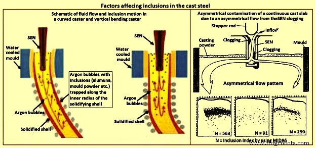
Fig 3 Factors affecting inclusions in cast steel
Casting machine curvature – Continuous casting machines with curved mould are known to entrap more particles than straight (vertical) mould casting machines (Fig 3), since the particles gradually move upwards towards the inside radius while they spiral with the liquid in the lower recirculation zone. Majority of the particles are captured 1 m to 3 m below the meniscus, independent of casting speed, which corresponds to a specific distance through the strand thickness. Frequently, inclusions concentrate at surface and one-eighth to one-fourth of the thickness from the top of the inside radius surface. The vertical bending casting machine has fewer inclusions and pinholes, which are distributed deeper, relative to the curved casting machine. Particle entrapment defects such as pencil pipe can be lessened if at least the top 2.5 m section of the casting machine is straight (vertical).
Inclusions detection methods
The quantity, size distribution, shape and composition of inclusions are required to be measured at all stages of the production of steel. Measurement techniques range from direct methods, which are accurate but costly, to indirect methods, which are fast and inexpensive, but are only reliable as relative indicators. The inclusion detection methods are sometimes divided into two categories namely (i) off-line methods, and (ii) online methods.
Direct methods
There are several direct methods to evaluate steel cleanliness. These methods are described below.
Inclusion evaluation of solid steel sections
Several traditional methods directly evaluate inclusions in a two dimensional section through solidified product samples. The last five of the methods described below add the ability to measure the composition of the inclusions.
Metallographic microscope observation (MMO) – MMO method can only reveal the two-dimensional section of an inclusion though the inclusions are three-dimensional in nature.
Image analysis (IA) – This enhancement to MMO improves on eye evaluation by using high speed computer evaluation of video-scanned microscope images to distinguish dark and light regions based on a grey scale cutoff.
Sulphur print – It is a popular and inexpensive macro-graphic method which distinguishes macro-inclusions and cracks by etching sulphur rich areas. It has the same issues as the other two-dimensional methods.
Scanning electron microscopy (SEM) – This method clearly reveals the three-dimensional morphology and the composition of each inclusion. Composition can also be measured with ‘electron probe micro analyzer’ (EPMA).However, extensive sample preparation is needed to find and expose the inclusion(s).
Optical emission spectrometry with pulse discrimination analysis (OES-PDA) – The optical emission spectrometry (OES) method analyzes elements dissolved in liquid steel. Inclusions cause high intensity spark peaks (relative to the background signal from the dissolved elements), which are counted to give the PDA (pulse discrimination analysis) index.
Laser micro-probe mass spectrometry (LAMMS) – In this method, individual particles are irradiated by a pulsed laser beam, and the lowest laser intensity above a threshold value of ionization is selected for its characteristic spectrum patterns due to their chemical states. Peaks in LAMMS spectra are associated with elements, based on comparison with reference sample results.
X-ray photoelectron spectroscopy (XPS) – This method use x-rays to map the chemical state of individual inclusions which greater than 10 micrometers in size.
Auger electron spectroscopy (AES) – This method use electron beams to map the composition of small areas near the surface of flat samples.
Cathodoluminescence microscope – Under microscope, the steel or lining sample section is stimulated by a cathode-ray (energetic electron-beam), to induce cathodoluminescence (CL). The colour of CL depends on the metal ions type, electric field, and stress, allowing inclusions to be detected.
Inclusion evaluation three-dimensional steel matrix
Several methods directly measure inclusions in the three-dimensional steel matrix. The first four of these scan through the sample with ultrasound or x-rays. The last four of these volumetric methods first separate the inclusions from the steel.
Conventional ultrasonic scanning (CUS ) – In this method, the transducer (typically a piezoelectric) emits a sound pressure wave which is transferred into the sample with the aid of a coupling gel. The sound waves propagate through the sample, reflect off at the back wall and return to the transducer. The magnitude of the initial input pulse and the reflected signals are compared on an oscilloscope to indicate the internal quality of the sample. Obstructing objects in the path of the sound scatters the wave energy. This non-destructive method detects and counts inclusions larger than 20 micrometers in the solidified steel samples.
Mannesmann inclusion detection by analysis surfboards (MIDAS) – In MIDAS method the steel samples are first rolled to remove the porosity and then ultrasonically scanned to detect both the solid inclusions and compound solid inclusions / gas pores. This method has been now renamed as the ‘liquid sampling hot processing’ (LSHP) method.
Scanning acoustic Microscope (SAM) – In this method, a cone-shaped volume of continuous cast product is scanned with a spiraling detector, such as a solid ultrasonic system, which automatically detects inclusions at every location in the area of the sample surface, including from surface to centre-line of the product.
X-ray detection – By this method, inclusions images are detected by their causing variation in the attenuation of x-rays transmitted through the solid steel. An inclusion distribution can be constructed by dividing a sample into several wafers and subjecting each to conventional x-rays to print penetrameter radiograghs for image analysis.
Chemical dissolution (CD) – In the CD method, acid is used to dissolve the steel and partially extract the inclusions. The inclusion morphology and composition can be detected by another method like SEM, or be fully extracted by dissolving the complete steel sample. The three dimensional nature of inclusions can be revealed by this method. The disadvantage is that the acid dissolves away FeO, MnO, CaO, and MgO in the inclusions. Hence, this method is good to detect only alumina and silica inclusions.
Slime (electrolysis) technique – This method is also called ‘potentiostatic dissolution technique’. A relatively large (200 grams to 2 kilograms) steel sample is dissolved by applying electric current through the steel sample immersed in a ferrous chloride or ferrous sulphate solution. This method is used to reveal the individual, intact inclusions. One disadvantage of this method is the cluster inclusions possibly break into separate particles after extraction from steel.
Electron beam (EB) melting – In this method, a sample of aluminum killed steel is melted by an electron beam under vacuum. Inclusions float to the upper surface and form a raft on top of the liquid sample. The normal EB index is the specific area of the inclusion raft. An enhanced method (EB-EV – ‘extreme value’) has been developed to estimate the inclusion size distribution.
Cold crucible (CC) melting – Inclusions are first concentrated at the surface of the melted sample as in the EB melting. After cooling, the sample surface is then dissolved, and the inclusions are filtered out of the solute. This method improves on EB melting by melting a larger sample and being able to detect silica.
Fractional thermal decomposition (FTD) – When temperature of a steel sample exceeds its melting point, inclusions can be revealed on the surface of the liquid and decomposed. Inclusions of different oxides are selectively reduced at different temperatures, such as alumina based oxides at 1,400 deg C or 1,600 deg C, or refractory inclusions at 1,900 deg C. The total oxygen content is the sum of the oxygen contents measured at each heating step.
Magnetic particle inspection (MPI) – This method also called magnetic leakage field inspection can locate inclusions larger than 30 micro-meters in steel sheet products. The test procedure consists of generating a homogeneous field within the steel sheet which is parallel to the sheet surface. If an inhomogeneity (such as an inclusion or a pore) is present, the difference in magnetic susceptibility forces the magnetic flux field to bend and extend beyond the surface of the sheet. The main disadvantage of this method is poor resolution of inclusions which are close together.
Inclusion size distribution after inclusion extraction
Several methods can find three-dimensional inclusion size distributions after the inclusions are extracted from the steel using a suitable method described earlier.
Coulter counter analysis – in this method, particles which flow into the sensor through its tiny hole are detected because they change the electric conductivity across a gap. The method measures the size distribution of inclusions extracted by slime and suspended in water.
Photo scattering method – Photo-scattering signals of inclusions (which have been extracted from a steel sample using another method such as slime, are analyzed to evaluate the size distribution.
Laser diffraction particle size analyzer (LDPSA) – This laser technique can evaluate the size distribution of inclusions which have been extracted from a steel sample using another method such as slime.
Inclusion evaluation of liquid steel
There are several approaches which can be used to detect the inclusion quantity and the size distribution in the liquid steel.
Ultrasonic techniques for liquid system – This method captures the reflections from ultrasound pulses to detect on-line inclusions in the liquid steel.
Liquid metal cleanliness analyzer (LIMCA) – This on-line sensor uses the principle of the ‘Coulter counter’ to detect inclusions directly in the liquid steel. This method is normally used for aluminum and other metals, and it is still under development for steel.
Confocal scanning laser microscope – This new in-situ method can observe the behaviour of individual inclusions moving on the surface of the liquid steel, including their nucleation, collision, agglomeration, and pushing by interfaces. The detected alumina inclusion clustering process on a liquid surface by this method is shown in Fig 4.
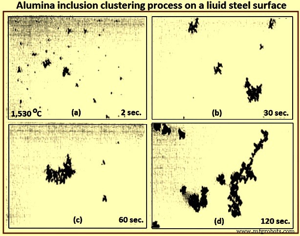
Fig 4 Alumina inclusion clustering process on a liquid steel surface
Electromagnetic visualization (EV) – This Lorentz-force-based detection system is used to accelerate inclusions to the top free surface of the sample of liquid metals and highly conductive opaque fluids. The technique has better resolution than other on-line methods.
Indirect methods
Owing to the cost, time requirements, and sampling difficulties of direct inclusion measurements, steel cleanliness is normally measured in the steel plants using total oxygen, nitrogen pickup, and other indirect methods.
Total oxygen measurement – The total oxygen in the steel is the sum of the free oxygen (dissolved oxygen) and the oxygen combined as inclusions. Free oxygen or ‘active’ oxygen can be measured relatively easily using oxygen sensors. It is controlled mainly by equilibrium thermodynamics with deoxidation elements, such as aluminum. Since the free oxygen does not vary much for example, 3 ppm to 5 ppm at 1,600 deg C for aluminum killed steel. The total oxygen is a reasonable indirect measure of the total amount of oxide inclusions in the steel since there is small population of large inclusions in the steel sample. Hence, the total oxygen content really represents the level of small oxide inclusions only. The total oxygen measured from liquid samples roughly correlates with the incidence of slivers in the product. In particular, tundish samples are normally taken to indicate cleanliness for the cast steel dispositioning.
One of the steel plants needs the total oxygen in the tundish samples less than 30 ppm to ensure shipment of cold-rolled sheet without special inspection. The general conclusions drawn from the data of the total oxygen levels in LCAK steel at each processing step at several steel plants are (i) total oxygen in LCAK steel has steadily decreased with passing years, as new technology is implemented, (ii) plants with RH (Rurhstahl Heraeus) degassing unit achieve lower total oxygen (10 ppm to 30 ppm) than plants with ladle gas stirring (35 ppm to 45 ppm), and (iii) the total oxygen normally drops after every processing step such as 40 ppm in the ladle, 25 ppm in the tundish, 20 ppm in the mould, and 15 ppm in the cast product. Fig 5 shows relationship between total oxygen in tundish and sliver defect index.
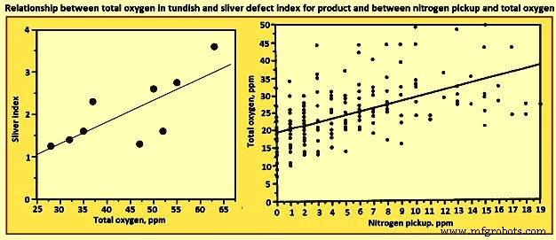
Fig 5 Relationship between total oxygen in tundish and sliver defect index for product and between nitrogen pickup and total oxygen
Nitrogen pickup – The difference in nitrogen content between steelmaking vessels is an indicator of the air entrained during transfer operations. Hence, nitrogen pickup serves as a crude indirect measure of total oxygen, steel cleanliness, and quality problems from reoxidation inclusions. For example, a steel plant restricts nitrogen pickup from ladle to tundish to less than 10 ppm for critical clean steel applications. The oxygen pickup is always many times higher than the measured nitrogen pickup, because of its faster absorption kinetics at the air steel interface. Fig 3 shows relationship between nitrogen pickup and total oxygen. In addition, nitrogen pickup is faster when the oxygen and sulphur contents are low. Hence, for the reduction of the nitrogen pickup, deoxidation is best carried out after tapping. Plant measurements confirm this, as nitrogen pickup reduced from 10 ppm to 20 ppm for deoxidation during tapping to 5 ppm after tapping.
The general conclusion drawn from the data of minimum nitrogen pickup and nitrogen contents measured in LCAK steel at every processing step (except tundish and mould) for several steel plants is that the nitrogen in LCAK steel cast products is around 30 ppm to 40 ppm at the majority of the steel plants. It is controlled mainly by the steelmaking converter or electric furnace operation, but is also affected by secondary steelmaking and shrouding operations. However, the nitrogen pickup is decreasing with passing years, because of new technologies and improved operations. Nitrogen pickup can be normally controlled at 1 ppm to 3 ppm from ladle to the mould. With optimal transfer operations to lessen air entrainment, this pickup can be lowered during steady state casting to less than 1 ppm.
Concentration measurement – For LCAK steels, the dissolved aluminum loss also indicates that reoxidation has occurred. However, this indicator is a less accurate measure than nitrogen pickup since aluminum can also be reoxidized by the slag. The silicon pickup, manganese pickup can be also used to evaluate the reoxidation process.
Lining refractory observation – Analysis of the lining refractory composition evolution before and after operations can be used to estimate inclusion absorption to the lining and the lining erosion. Also, the origin of a complex oxide inclusion can be traced to lining refractory erosion by matching the mineral and element fractions in the slag with the inclusion composition.
Slag composition measurement – Analysis of the slag composition evolution before and after operations can be interpreted to estimate inclusion absorption to the slag. Also, the origin of a complex oxide inclusion can be traced to slag entrpment by matching the mineral and element fractions in the slag with the inclusion composition. However, these methods are not easy because of the sampling difficulties and since changes in the thermodynamic equilibrium are to be taken into account.
Tracer studies for determining exogenous inclusions from slag and lining erosion – Tracer oxides can be added into slags and linings in ladle, tundish, mould, or ingot trumpet, and top compound. Typical inclusions in the steel are then analyzed by SEM and other methods. If the tracer oxides are found in these inclusions, then the source of these inclusions can be decided.
Submerged entry nozzle (SEN) clogging – Short SEN life due to clogging is sometimes an indicator of poor steel cleanliness. The composition of a typical clog during LCAK steel continuous casting consists of Al2O3- 51.7 %, Fe – 44 %, MnO – 2.3 %, SiO2 – 1.4 %, and CaO – 0.6 % , which shows that nozzle clogs are frequently caused by a simultaneous build-up of small alumina inclusions and frozen steel. Hence, SEN clogging frequency is another crude method to evaluate steel cleanliness.
Final product tests
The ultimate measure of cleanliness is to use destructive mechanical tests to measure formability, deep-drawing, and / or bending properties of the final sheet product, or fatigue life of test samples or product samples. Other steel sheet tests include the HIC test and magnetoscopy. Another example is the inclusion inspection method in ultra-sonic fatigue test. These tests are needed to reveal facts such as the potential benefit of very small inclusions (less than 1 micrometer), which are not to be counted against cleanliness.
It can be seen from the above that there is no single ideal method to evaluate steel cleanliness. Some methods are better for quality monitoring while others are better for problem investigation. Hence, it is necessary to combine several methods together to give a more accurate evaluation of steel cleanliness in a given operation.
Since exogenous inclusions can originate from a combination of several sources, methods for their prevention are not likely to be simple. It is only through the correct combination of all these sources and removal mechanisms that the incidence of large inclusions in the steels can be reduced. For the detection of the exogenous inclusions in steel, the methods which are suitable are ultrasonic scanning, microscopic observation, sulphur print, slime (electrolysis), X-ray, SEM, slag composition analysis, and refractory observation.
Processo de manufatura
- Efeito das inclusões nas propriedades do aço
- Inclusões em siderurgia e siderurgia secundária
- Inclusões, Engenharia de Inclusão e Aços Limpos
- Automação, Instrumentação e Modelagem de Lingotamento Contínuo de Aço
- Fornos de reaquecimento e seus tipos
- AMPCO® 25 elenco contínuo
- AMPCO® 18 Conjuração contínua
- AMPCO® 22 elenco contínuo
- AMPCO® 21 Conjuração contínua
- AMPCO® 18.23 Contínua